Volume 2007, Article ID 31319,12pages doi:10.1155/2007/31319
Research Article
A Motion-Compensated Overcomplete Temporal
Decomposition for Multiple Description Scalable
Video Coding
Christophe Tillier, Teodora Petris¸or, and B ´eatrice Pesquet-Popescu
Signal and Image Processing Department, ´Ecole Nationale Sup´erieure des T´el´ecommunications (ENST), 46 Rue Barrault, 75634 Paris C´edex 13, France
Received 26 August 2006; Revised 21 December 2006; Accepted 23 December 2006
Recommended by James E. Fowler
We present a new multiple-description coding (MDC) method for scalable video, designed for transmission over error-prone net-works. We employ a redundant motion-compensated scheme derived from the Haar multiresolution analysis, in order to build temporally correlated descriptions in at+ 2Dvideo coder. Our scheme presents a redundancy which decreases with the resolution level. This is achieved by additionally subsampling some of the wavelet temporal subbanbds. We present an equivalent four-band lifting implementation leading to simple central and side decoders as well as a packet-based reconstruction strategy in order to cope with random packet losses.
Copyright © 2007 Christophe Tillier et al. This is an open access article distributed under the Creative Commons Attribution License, which permits unrestricted use, distribution, and reproduction in any medium, provided the original work is properly cited.
1. INTRODUCTION
With the increasing usage of the Internet and other best-effort networks for multimedia communication, there is a stringent need for reliable transmission. For a long time, the research efforts have been concentrated on enhancing the ex-isting error correction techniques, but during the last decades an alternative solution has emerged and is gaining more and more popularity. This solution mainly answers the situation in which immediate data retransmission is either impossible (network congestion or broadcast applications) or undesir-able (e.g., in conversational applications with very low de-lay requirements). We are referring to a specific joint source-channel coding technique known asmultiple-description cod-ing(MDC). A comprehensive presentation of MDC is given in [1].
The MDC technique leads to several correlated but inde-pendently decodable (preferably with equivalent quality) bit-streams, calleddescriptions, that are to be sent over as many independent channels. In an initial scenario, these channels have an on-offfunctioning: either the bitstream is flawlessly conveyed or it is considered unusable at the so-calledside de-coderend if an error had occurred during the transmission. According to this strategy, some amount of redundancy has
to be introduced at the source level such that an acceptable reconstruction can be achieved from any of the bitstreams. Then, the reconstruction quality will be enhanced with every bitstream received.
The application scenario for MDC is different from the one of scalable coding, for example. Indeed, the robustness of a scalable system relies on the assumption that the infor-mation has been hierarchized and the base layer is received without errors (which can be achieved, e.g., by adding suffi -cient channel protection). However, if the base layer is lost, the enhancement layers cannot be exploited and nothing can be decoded. The MDC framework has a complementary ap-proach, trying to cope with the channel failures, and thus al-lowing the decoding of at least one of the descriptions, when the other is completely lost.
An ingredient enabling the success of an MDC technique is the path diversity, since its usage balances the network load and reduces the congestion probability.
frequency the transmission of the two descriptions: for ex-ample, a laptop may be equipped with two wireless cards (e.g., 802.11a and 802.11g), each wireless card receiving a dif-ferent description. Depending on the dynamic changes in the number of clients in each network, one of them may become overloaded and the corresponding description may not be transmitted.
In wired networks, the different descriptions can be routed to a receiver through different paths by incorporat-ing this information into the packet header [2]. In this sit-uation, a description might contain several packets and the scenario of on-offchannels might no longer be suitable. The system should, in this case, be designed to take into consider-ation individual or bursty packet losses rather than a whole description.
An important issue that concerned the researchers over the years is the amount of introduced redundancy. One has to consider the tradeoffbetween this redundancy and the re-sulting distortion. Therefore, a great deal of effort has been spent on defining the achievable performances with MDC ever since the beginning of this technique [3,4] and until recently, for example, [5]. Practical approaches to MDC in-clude scalar quantization [6], correlating transforms [7], and frame expansions [8]. Our work belongs to the last category and we concentrate on achieving a tunable low redundancy while preserving the perfect reconstruction property of our scheme [9].
In this paper, we present an application of multiple-description coding to robust video transmission over lossy networks, using redundant wavelet decompositions in the temporal domain of at+ 2Dvideo coder.
Several directions have already been investigated in the literature for MD video coding. In [10–13], the proposed schemes mainly involve the spatial domain in hybrid video coders such as MPEG/H.26x. A very good survey on MD video coding for hybrid coders is given in [14].
Only few works investigated the design of MDC schemes allowing to introduce source redundancy in the temporal do-main, although the field is very promising. In [15], a bal-anced interframe multiple-description coder has been pro-posed starting from the popular DPCM technique. In [16], the reported MDC scheme consists in temporal subsampling of the coded error samples by a factor of 2 so as to obtain 2 threads at the encoder, which are further independently en-coded using prediction loops that mimic the decoders (two side prediction loops and a central one).
Existing work for t+ 2D video codecs with temporal redundancy addresses three-band filter banks [17,18] and temporal or spatiotemporal splitting of coefficients in 3D-SPIHT sytems [19–21]. Here, we focus on a two-description coding scheme for scalable video, where temporal and spa-tial scalabilities follow from a classical dyadic subband trans-form. The correlation between the two descriptions is in-troduced in the temporal domain by exploiting an oversam-pled motion-compensated filter bank. An important feature of our proposed scheme is its reduced redundancy which is achieved by an additional subsampling of a factor of two of the resulting temporal details. The remaining details are
then distributed in a balanced manner between the two de-scriptions, along with the nondecimated approximation co-efficients. The global redundancy is thus tuned by the num-ber of temporal decomposition levels. We adopt a lifting ap-proach for the temporal filter-bank implementation and fur-ther adapt this scheme in order to design simple central (re-ceiving both descriptions) and side decoders.
This paper relies on some of our previous work which is presented in [22]. Here, we consider an improved version of the proposed scheme and detail its application to robust video coding. The approximation subbands which partici-pate in each description are decorrelated by an additional motion-compensated transform, as it will be explained in
Section 5. Moreover we consider two transmission scenarios. In the first one, we tackle the reconstruction when an en-tire description is lost or when both descriptions are received error-free, and in the second one we discuss signal recovery in the event of random packet losses in each description. For the random-loss case, we compare our results with a tempo-ral splitting strategy, as in [2], which consists in partitioning the video sequence into two streams by even/odd temporal subsampling and reconstructing it at half rate if one of the descriptions is lost.
An advantage of our scheme is to maintain the scalabil-ity properties for each of the two created descriptions, allow-ing to go further than the classical on-offchannel model for MDC and also cope with random packet losses on the chan-nels.
The rest of the paper is organized as follows. InSection 2
we present the proposed strategy of building two temporal descriptions.Section 3gives a lifting implementation of our scheme together with an optimized version well suited for Haar filter banks. We explain the generic decoding approach inSection 4. We then discuss the application of the proposed scheme to robust video coding inSection 5and the resulting decoding strategy inSection 6.Section 7gives the simulation results for the two scenarios: entire description loss and ran-dom packet losses in each description. Finally,Section 8 con-cludes the paper and highlights some directions for further work.
2. TEMPORAL MDC SCHEME
The strategy employed to build two temporal descriptions from a video sequence is detailed in this section. We rely on a temporal multiresolution analysis of finite energy signals, associated with a decomposition onto a Riesz wavelet basis.
Throughout the paper, we are using the following nota-tions. The approximation subband coefficients are denoted byaand the detail subband coefficients byd. The resolution level associated with the wavelet decomposition is denoted by j, whereasJstands for the coarsest resolution. The tem-poral index of each image in the temtem-poral subbands of the video sequence is designated bynand the spatial indices are omitted in this section in order to simplify the notations.
the coefficients in the first basis from those corresponding to the second one. For example,dI
j,nstands for the detail coeffi-cient in representation I at resolutionjand temporal indexn. Then a secondary subsampling strategy is applied along with distributing the remaining coefficients into two descriptions. The redundancy is reduced by this additional subsampling to the size of an approximation subband (in terms of number of coefficients).
Let (hn)n∈Z (resp., (gn)n∈Z) be the impulse responses of the analysis lowpass (resp., highpass) filter corresponding to the considered multiresolution decomposition.
For the firstJ−1 resolution levels, we perform a standard wavelet decomposition, which is given by
aI j,n=
k
h2n−kaIj−1,k (1)
for the temporal approximation subband, and by
dIj,n=
k
g2n−kaIj−1,k (2)
for the detail one, wherej∈ {1,. . .,J−1}.
We introduce the redundancy at the coarsest resolution levelJby eliminating the decimation of the approximation coefficients (as in a shift-invariant analysis). This leads to the following coefficient sequences:
aIJ,n=
k
h2n−kaIJ−1,k,
aIIJ,n=
k
h2n−1−kaIJ−1,k.
(3)
Each of these approximation subbands is assigned to a de-scription.
In the following, we need to indicate the detail subbands involved in the two descriptions. At the last decomposition stage, we obtain in the same manner as above two detail co-efficient sequences (as in a nondecimated decomposition):
dJI,n=
k
g2n−kaIJ−1,k,
dJII,n=
k
g2n−1−kaIJ−1,k.
(4)
Note that the coefficients in representation II are obtained with the same even-subsampling, but using the shifted ver-sions of the filtershandg:hn−1andgn−1, respectively.
In order to limit the redundancy, we further subsample these coefficients by a factor of 2, and we introduce the fol-lowing new notations:
dI
J,n=dJI,2n, (5)
ˇ
dIIJ,n=dJII,2n−1. (6)
At each resolution, each description will contain one of these detail subsets.
Summing up the above considerations, the two descrip-tions are built as follows.
Description 1. This description contains the even-sampled detail coefficients (dI
j,n)n for j ∈ {1,. . .,J}, and (aIJ,n)n, where, using the same notation as in (5),
dj,nI =dj,2n. (7)
Description 2. This description contains the odd-sampled detail coefficients ( ˇdI
j,n)nfor j ∈ {1,. . .,J−1}, ( ˇdIIJ,n)n, and (aII
J,n)n, where, similarly to (6), ˇ
dI
j,n=dj,2n−1. (8) Once again, we have not introduced any redundancy in the detail coefficients, therefore the overall redundancy factor (evaluated in terms of number of coefficients) stems from the last level approximation coefficients, that is, it is limited to 1 + 2−J.
The choice of the subsampled detail coefficients at the coarsest level in the second description is motivated by the concern of having balanced descriptions [9].
3. LIFTING-BASED DESIGN OF THE ENCODER
3.1. Two-band lifting approach
Since the firstJ−1 levels are obtained from a usual wavelet analysis, in the following we will be interested mainly in the last resolution level. The corresponding coefficients in the two descriptions are computed as follows:
aI n=
k
h2n−kxk, (9a)
dI n =
k
g4n−kxk, (9b)
aII n =
k
h2n−1−kxk, (9c)
ˇ
dII n =
k
g4n−3−kxk, (9d)
where, for simplicity, we have denoted byxkthe approxima-tion coefficients at the (J−1)th level and we have omitted the subscriptJ.
We illustrate our scheme inFigure 1, using a one-stage lifting implementation of the filter bank. Thepandu opera-tors in the scheme stand for the predict and update, respec-tively, andγis a real nonzero multiplicative constant. Note that the lifting scheme allows a quick and memory-efficient implementation for biorthogonal filter banks, but especially it guarantees perfect reconstruction. For readability, we dis-play a scheme with only two levels of resolution, using a basic lifting core.
3.2. Equivalent four-band lifting implementation
a0,2n
1
γa1,n
+
+ ×
−p u z 2↓ 2↓
a0,2n+1
1
γ
1
γa1,2n
1
γa1,2n+1
−p u
2↓ 2↓ 2↓
2↓ z−1
−p u
z−1 z−1
1
γa1,2n−1 +
+
+ +
γ
γ ×
× aI
2,n
dI 2,n
dI 1,n
ˇ dI 1,n
aII2,n
ˇ d2,IIn
D1
D2
Figure1: Two-band lifting implementation of the proposed multiple-description coder for the last two resolution levels.
video. This is the motivation behind searching an equiva-lent scheme for which global inversion would be easier to prove. In the following, we build a simpler equivalent lift-ing scheme for the Haar filter bank, by uslift-ing directly the four-band polyphase components of the input signal, instead of the two-band ones. Let these polyphase components of (xn)n∈Zbe defined as
∀i∈ {0, 1, 2, 3}, x(i)n =x4n+i. (10)
For the first description, the approximation coefficients can be rewritten from (9a), while the detail coefficients are still obtained with (9b), leading to
aI
n=aI2n=
k
h4n−kxk,
ˇ
aI
n=aI2n−1=
k
h4n−2−kxk,
dnI=
k
g4n−kxk.
(11)
Similarly, for the second description, we express the approx-imation subband from (9c) and keep the details from (9d):
aII n =
k
h4n−1−kxk,
ˇ
aII n=
k
h4n−3−kxk,
ˇ
dII n =
k
g4n−3−kxk.
(12)
Note that the coefficients in the two descriptions can thus be computed with an oversampled six-band filter bank with a decimation factor of 4 of the input signal, which conse-quently amounts to a redundant structure.
In the sequel of this paper, we will focus on the Haar fil-ter banks, which are widely used for the temporal decompo-sition int+ 2Dwavelet-based video coding schemes.
To go further and find an equivalent scheme for the Haar filter bank, note that the two-band polyphase components of the input signal,x2n=aJ−1,2nandx2n+1 =aJ−1,2n+1, are first
filtered and then subsampled (seeFigure 1). However, for the
Haar filter bank, recall that the predict and update operators are, respectively,p =Id andu=(1/2) Id (and the constant
γ =√2). Since these are both instantaneous operators, one can reverse the order of the filtering and downsampling op-erations. This yields the following very simple expressions for the coefficients in the first description:
anI=
x4n+√x4n+1
2 =
x(0)n √+x(1)n
2 , (13a)
ˇ
aI n=
x4n−2√+x4n−1
2 =
xn(2)−1+x (3) n−1
√
2 , (13b)
dI n=
x4n+1√−x4n
2 =
xn(1)√−x(0)n
2 , (13c)
and in the second:
aII n =
x4n+√x4n−1
2 =
x(0)n √+x(3)n−1
2 , (14a)
ˇ
aII n=
x4n−2√+x4n−3
2 =
xn(2)−1√+xn(1)−1
2 , (14b)
ˇ
dII n=
x4n−2√−x4n−3
2 =
x(2)n−1−x (1) n−1
√
2 . (14c)
InFigure 2, we schematize the above considerations.
4. RECONSTRUCTION
In this section, we give the general principles for decoders design considering the generic scheme inFigure 2. The next sections will discuss the application of the proposed scheme to robust video coding and more details will be given about the central and side decoders in the video coding schemes. Some structure improvements that lead to better reconstruc-tion will also be presented.
x(0)n
x(1)n
x(2)n
x(3)n
z−1
z−1
z−1
z−1 + + Haar lifting Haar lifting 1 √ 2 1 √ 2 aI n dI n ˇ aII n ˇ dII n ˇ aI n aII n × ×
Figure2: Redundant four-band lifting scheme.
reconstruction. Let us denote the recovered polyphase com-ponents of the signal byxn(i).
4.1. Central decoder
We first discuss the reconstruction performed at the central decoder. The first polyphase component ofxnis obtained by directly inverting the basic lifting scheme represented by the upper block inFigure 2. The polyphase components recon-structed fromaI
nanddnIare denoted byy (0)
n andy(1)n . Thus, we obtain
xn(0)=yn(0)=
aI n
− dI n
√
2 , (15)
where [aI
n] and [dnI] are the quantized versions ofanI and
dI
n, analogous notations being used for the other coefficients. Obviously, in the absence of quantization, we havex(0)n =yn(0) andxn(1)=y(1)n .
Similarly, the third polyphase component is recon-structed by directly inverting the second two-band lifting block inFigure 2:
xn(2)=z(2)n+1=
ˇ
aII n+1
+dˇII
n+1
√
2 , (16)
where the polyphase components reconstructed from ˇaII nand ˇ
dII
nare denoted byz(1)n andzn(2).
The second polyphase component ofxncan be recovered as the average between the reconstructed subbands from the two previous lifting blocks:
x(1) n = 1 2 y(1) n +z
(1) n+1
= 1
2√2 a I n
+ dI n
+aˇII n+1
−dˇII n+1
.
(17)
The last polyphase component of the input signal can be computed as the average between the reconstructions from
ˇ
aI
nandanII. Using (13b) and (14a), we get
xn(3)= − 1 2
yn+1(0) +zn+1(2)
+√1 2 aˇ
I n+1
+an+1II
= − 1
2√2 a I n+1
− dI n+1
+aˇII
n+1
+dˇII n+1
+√1 2 aˇ
I n+1
+aII
n+1
.
(18)
4.2. Side decoders
Concerning the side decoders, again fromFigure 2, we note that from each description we can partially recover the orig-inal sequence by immediate inversion of the scheme. For in-stance, if we only receive the first description, we can easily reconstruct the polyphase componentsxn(0),xn(1)from the first Haar lifting block. The last two polyphase componentsxn(2) andxn(3)are reconstructed by assuming that they are similar:
x(2)
n =xn(3)= ˇ aI n+1 √
2 . (19)
Similarly, when receiving only the second description, we are able to directly reconstructx(1)n ,xn(2)from the second Haar lifting block, whilexn(0)andxn(3)are obtained by duplicating
aII n+1:
xn+1(0) =xn(3)= aII n+1 √
2 . (20)
5. APPLICATION TO ROBUST VIDEO CODING
Let us now apply the described method to robust coding of video sequences. The temporal samples are in this case the input frames, and the proposed wavelet frame decomposi-tions have to be adapted to take into account the motion estimation and compensation between video frames, which is an essential ingredient for the success of such temporal decompositions. However, as shown in the case of critically sampled two-band and three-band motion-compensated fil-ter banks [23–25], incorporating the ME/MC in the lifting scheme leads to nonlinear spatiotemporal operators.
Let us consider the motion-compensated prediction of a pixelsin the framex(1)n from the framexn(0)and denote byv the forward motion vector corresponding tos. Writing now (13a)–(13c) in a lifting form and incorporating the motion into the predict/update operators yield
dI n(s)=
x(1)n (s)−√xn(0)(s−v)
2 ,
aI
n(s−v)=
√
2x(0)
n (s−v) +dnI(s),
ˇ
aI n(s)=
x(2)n−1(s) +√ x(3)n−1(s)
2 .
(21)
connected [26]. Then, for the pixelssiand their correspond-ing motion vectorsvi, we haves1−v1 = · · · = si−vi =
· · · =sN−vN. After noting that the update step may involve all the detailsdI
n(si),i∈ {1,. . .,N}, while preserving the per-fect reconstruction property, we have shown that the update step minimizing the reconstruction error is the one averag-ing all the detail contributions from the connected pixelssi [27]. With this remark, one can write (21) as follows:
dnI si
=x
(1) n si
−x(0)n si−vi
√
2 , i∈ {1,. . .,N}, (22a)
aI n si−vi
=√2x(0) n si−vi
+
N =1dnI s
N , (22b)
ˇ
aI n(s)=
xn(2)−1(s) +x (3) n−1(s)
√
2 , (22c)
and with similar notations for multiple connections in the second description:
ˇ
dII n si
= x
(2) n−1 si
−xn(1)−1 si−vi
√
2 , i∈ {1,. . .,M}, (23a)
ˇ
aII n si−vi
=√2x(1)n−1 si−vi
+ M
=1dˇIIn s
M , (23b)
aII n(s)=
xn(0)(s) +√xn(3)−1(s)
2 . (23c)
Since for video coding efficiency, motion prediction is an im-portant step, we propose an alternative scheme for building the two descriptions, in which we incorporate the motion estimation/compensation in the computation of the second approximation sequence (aI
n, resp., ˇaIIn). This scheme is illus-trated inFigure 3. Per description, an additional motion vec-tor field needs to be encoded. In the following, this scheme will be referred to as 4B 1MV. In the case of the 4B 1MV scheme, if we denote byuthe motion vector predicting the pixelsin framexn(3)−1 fromxn(2)−1 and byw the motion vec-tor predicting the pixelsin framexn(0)fromxn(3)−1, the analysis equations foraI
nand ˇaIIncan be written as
ˇ
aI
n(s−u)=
xn(3)−1(s) +√xn(2)−1(s−u)
2 , (24)
anII(s−w)=
xn(3)−1(s−w) +x (0) n (s)
√
2 (25)
for the connected pixels (here, only the first pixel in the scan order is considered in the computation), and
ˇ
aIn(s)=
√
2x(2)n−1(s),
anII(s)=
√
2x(3)n−1(s)
(26)
for the nonconnected pixels.
x(0)n
x(1)n
x(2)n
x(3)n
ME
ME z−1
z−1
z−1
z−1 + + Haar lifting + ME Haar lifting + ME 1 √ 2 1 √ 2 aI n dI n ˇ aII n ˇ dII n ˇ aI n aII n × ×
Figure3: Four-band lifting scheme with motion estimation on the
approximation subbands.
Furthermore, a careful analysis of the video sequences encoded in each description revealed that the two polyphase components of the approximation signals that enter each description are temporally correlated. This suggested us to come up with a new coding scheme, illustrated inFigure 4, where a motion-compensated temporal Haar transform is applied on aI
n and ˇaIn(resp., on ˇaIIn andanII). Compared to the original structure, two additional motion vector fields have to be transmitted. The scheme will thus be referred to as 4B 2MV. InFigure 5the temporal transforms involved in two levels of this scheme are represented. One can note the temporal subsampling of the details on the first level and the redundancy at the second level of the decomposition.
6. CENTRAL AND SIDE VIDEO DECODERS
The inversion of (22a) and (22b) is straightforward by the lifting scheme, allowing us to reconstruct the first two polyphase components. Using the same notations as in
Section 4, the reconstructed polyphase components from the first description are as follows:
x(0) n si−vi
=√1
2
aI n si−vi
− 1 N N =1 dI n s , x(1) n si
=√1
2
aI n si−vi
+2 dI
n si − 1 N N =1 dI n s . (27)
When analyzing the reconstruction of the connected pixels in the first two polyphase components, one can note that it corresponds to the inverse lifting using the average update step.
x(1)n
x(0)n
x(3)n
x(2)n ME ME
z−1
z−1
z−1
+ + Haar lifting + ME Haar lifting + ME Haar lifting + ME Haar lifting + ME 1 √ 2 1 √ 2 × × dI n aI n ˇ aI n ˇ dII n ˇ aII n aII n
Figure4: Four-band lifting scheme with motion estimation and Haar transform on the approximation subbands.
16(n−1) 16n 16(n+ 1)
1st level
dI
4n−4 dI4n−3 d4In−2 dI4n−1 d4In d4In+1 dI4n+2 d4In+3 Description 1 ˇ
dI
4n−4 dˇ4In−3 dˇ4In−2 dˇI4n−1 dˇI4n dˇI4n+1 dˇI4n+2 dˇI4n+3 Description 2 2nd level
d2In−1 d2In d2In+1 Description 1
ˇ
d2In−1 dˇ2In dˇI2n+1 dˇI2n+2 Description 2
3rd level
ˇ aI
n aIn dnI aˇIn+1 aIn+1 Description 1
ˇ aII
n dˇIIn aIIn aˇnII+1 dˇIIn+1 aIIn+1 Description 2
Figure5: 4B 2MV scheme over 3 levels (GOP size=16). Motion-compensated temporal operations are represented by arrows (solid lines
for the current GOP, dashed lines for the adjacent GOPs).
frames ˇaII
n, ˇdnII, andanII. By inverting (23a) and (23b), we ob-tain
x(1) n si−vi
=√1
2
ˇ
aII
n+1 si−vi − 1 M M =1 ˇ dII n+1 s , x(2) n si
=√1
2
ˇ
aII
n+1 si−vi
+ 2dˇII n+1 si
− 1 M M =1 ˇ dII n+1 s . (28)
For the nonconnected pixels, we have
x(0) n si
= √1
2
aI n si
,
xn(1) si
= √1
2
ˇ
aIIn+1 si)
.
(29)
As it can be seen,xn(1) can be recovered from both de-scriptions, and the final central reconstruction is obtained as the mean of these values. Also, one can note that by knowing
xn(2)−1(resp.,x(0)n ) from the first (resp., second) description, it is possible to reconstructxn(3)−1, by reverting to (24) and (25). As for the side decoders of the initial scheme, the solution
for the first description is given by (27) and
x(2)
n (s)=xn(3)(s)= 1 √ 2 ˇ aI n+1(s)
, (30)
while for the second description it reads
xn+1(0)(s)=xn(3)(s)= 1 √ 2 ˇ aII n+1(s)
, (31)
in addition toxn(1)andxn(2)obtained with (28).
For the 4B 1MV scheme, the additional motion compen-sation involved in the computation of the approximation se-quences requires reverting the motion vector field in one of the components. Thus, we have
xn(2)−1(s)=
ˇ
aI n(s)
√
2 ,
xn(3)−1(s)=
ˇ
aI n(s−u)
√
2
(32)
for the first side decoder and
xn(3)−1(s)=
aII n(s)
√
2 ,
x(0) n (s)=
aII n(s−u)
√
2
(33)
For the scheme 4B 2MV, the temporal Haar transform being revertible, no additional difficulties appear for the cen-tral or side decoders.
Note that the reconstruction by one central and two side decoders corresponds to a specific application scenario, in which the user receives the two descriptions from two differ-ent locations (e.g., two WiFi access points), but depending on its position, it can receive both or only one of the descrip-tions. In a more general scenario, the user may be in the re-ception zone of both access points, but packets may be lost from both descriptions (due to network congestion, trans-mission quality, etc.). In this case, the central decoder will try to reconstruct the sequence by exploiting the information in all the received packets. It is therefore clear that an important issue for the reconstruction quality will be the packetization strategy. Even though the complete description of the differ-ent situations which can appear in the decoding (depending on the type of the lost packets) cannot be done here, it is worth noting that in a number of cases, an efficient usage of the received information can be employed: for instance, even if we do not receive the spatiotemporal subbands of one of the descriptions, but only a packet containing its motion vectors, these vectors can be exploited in conjunction with the other description for improving the fluidity of the recon-structed video. We also take advantage of the redundancy ex-isting at the last level to choose, for the frames which can be decoded from both descriptions, the version which has the best quality, and thus to limit the degradations appearing in one of the descriptions.
7. SIMULATIONS RESULTS
The Haar lifting blocks in Figure 4 are implemented by a motion-compensated lifting decomposition [23]. The mo-tion estimamo-tion is performed using hierarchical variable size block-matching (HVBSM) algorithm with block sizes rang-ing from 64×64 to 4×4. An integer-pel accuracy is used for motion compensation. The resulting temporal subbands are spatially decomposed with biorthogonal 9/7 Daubechies wavelets over 5 resolution levels. Spatiotemporal coefficients and motion vectors (MVs) are encoded within the MC-EZBC framework [26,28], where MV fields are first repre-sented as quad-tree maps and MV values are encoded with a zero-order arithmetic coder, in raster-scan order.
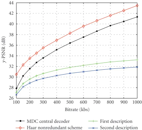
First, we have tested the proposed algorithm on several QCIF sequences at 30 fps. InFigure 6, we compare the rate-distortion performance of the nonrobust Haar scheme with that of the MDC central decoder on the “Foreman” video test sequence. The bitrate corresponds to the global rate for the robust codec (both descriptions). Three temporal decom-position levels have been used in this experiment (J = 3). We can observe that even the loss of one description still al-lows for acceptable quality reconstruction especially at low bitrates and also that the global redundancy does not exceed 30% of the bitrate.
Figure 7illustrates the central rate-distortion curves for different levels of redundancy and, together withFigure 6, shows the narrowing of the gap with respect to the
nonre-26 28 30 32 34 36 38 40 42 44
y
-PSNR
(dB)
100 200 300 400 500 600 700 800 900 1000 Bitrate (kbs)
MDC central decoder Haar nonredundant scheme
First description Second description
Figure 6: Central and side rate-distortion curves of the MDC
scheme compared with the nonrobust Haar codec (“Foreman” QCIF sequence, 30 fps).
24 26 28 30 32 34 36 38 40 42
y
-PSNR
(dB)
100 200 300 400 500 600 700 800 900 1000 Bitrate (kbs)
3 decomposition levels 2 decomposition levels 1 decomposition level
Figure7: Rate-distortion curves at the central decoder for several
levels of redundancy.
dundant version when the number of decomposition levels increases.
The difference in performance between the two descrip-tions is a phenomenon appearing only if the scheme involves three or more decomposition levels, since it is related to an asymmetry in the GOF structure of the two descriptions when performing the decimation. Indeed, as illustrated in
26 28 30 32 34 36 38 40 42 44
y
-PSNR
(dB)
100 200 300 400 500 600 700 800 900 1000 Bitrate (kbs)
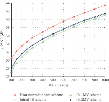
Haar nonredundant scheme Initial 4B scheme
4B 1MV scheme 4B 2MV scheme
Figure8: Rate-distortion curves for different reconstruction
strate-gies, central decoder (“Foreman” QCIF sequence, 30 fps).
26 27 28 29 30 31 32 33 34
y
-PSNR
(dB)
100 200 300 400 500 600 700 800 900 1000 Bitrate (kbs)
Initial 4B scheme 4B 1MV scheme 4B 2MV scheme
Figure9: Rate-distortion curves for different reconstruction
strate-gies, first side decoder (“Foreman” QCIF sequence, 30 fps).
to improve the reconstruction, while this does not happen when loosing the second description.
In Figures8-9, we present the rate-distortion curves for the central and side decoders, in the absence of packet losses. The performance of the scheme without ME/MC in the com-putation of the approximation sequences ˇaI
nandanIIis com-pared with the 4B 1MV and 4B 2MV schemes.
One can note that the addition of the ME/MC step in the computation of ˇaI
nandanII does not lead to an increase in
the coding performance of the central decoder, since the ex-pected gain is balanced by the need to encode an additional MV field. On the other hand, the final MC-Haar transform leads to much better results, since instead of two correlated approximation sequences, we now only have transformed subbands. For the side decoders however, the introduction of the motion-compensated average in the computation of ˇaI n andaII
n leads to a significant improvement in coding perfor-mances (increasing with the bitrate from 1 to 2.5 dB), and the MC-Haar transform adds another 0.3 dB of improvement.
In a second scenario, we have tested our scheme for trans-mission over a packet loss network, like Ethernet. In this case, the bitstreams of the two descriptions are separated in pack-ets of maximal size of 1500 bytes. For each GOP, separate packets are created for the motion vectors and for each spa-tiotemporal subband. If the packet with motion vectors is lost, or if the packet with the spatial approximation subband of the temporal approximation subband is lost, then we con-sider that the entire GOP is lost (it cannot be reconstructed). We compare our scheme with a nonredundant MCTF one and also with another temporal MDC scheme, consist-ing in a temporal splittconsist-ing of the initial video sequence. Odd and even frames are separated into two descriptions which are encoded with a Haar MCTF coder (Figure 10illustrates the motion vectors and temporal transforms for this struc-ture).
The coding performance as a function of the packet loss rate is illustrated in Figures 11 and12 for the “Foreman” and “Mobile” video test sequences at 250 kbs. As expected, when there is no loss, the nonredundant coding is better than both MDC schemes (which have comparable performances). However, as soon as the packet loss rate gets higher than 2%, our scheme overpasses by 0.5–1 dB the temporal splitting and the nonrobust coding by up to 4 dB.
Moreover, we have noticed that the MDC splitting scheme exhibits a flickering effect, due to the fact that a lost packet will degrade the quality of one over two frames. In our scheme, this effect is not present, since the errors in one description have limited influence thanks to the existing re-dundancies, and also to a different propagation during the reconstruction process.
Figure 13 presents the influence of the average update operator, with gains of about 0.2 dB over the entire range of packet loss rates. Finally, we have compared inFigure 14
16(n+ 1) 16n 16(n+ 1)
1st level dI
1,4n−4 d1,4I n−3 dI1,4n−2 dI1,4n−1 d1,4I n dI1,4n+1 d1,4I n+2 dI1,4n+3 Description 1 dII
1,4n−4 dII1,4n−3 d1,4IIn−2 dII1,4n−1 dII1,4n dII1,4n+1 dII1,4n+2 d1,4IIn+3 Description 2
2nd level dI
2,2n−2 d2,2I n−1 dI2,2n dI2,2n+1 Description 1
d2,2IIn−2 d2,2IIn−1 d2,2IIn dII2,2n+1 Description 2
3rd level aI
3,n−1 dI3,n−1 aI3,n dI3,n Description 1
aII
3,n−1 dII3,n−1 aII3,n d3,IIn
Description 2
Figure10: Three levels of decomposition in the temporal splitting scheme.
18 20 22 24 26 28 30 32 34 36
y
-PSNR
(dB)
0 5 10 15 20
Packet loss rate (%) Haar nonredundant scheme Temporal splitting scheme Proposed MDC scheme
Figure11: Distortion versus packet loss rate (“Foreman” QCIF
se-quence, 30 fps, 250 kbs).
approximation subband has to be coded into two packets. Moreover, we considered that if any of these two packets is lost, the GOF cannot be reconstructed. Therefore, we see a drop in performance. From this point, with the increasing bitrate, the performance improves till a new threshold where the subband needs to be encoded into three packets and so on. A better concealment scheme in the spatial domain, al-lowing to exploit even a partial information from this sub-band, would lead to a monotonic increase in performance.
8. CONCLUSION AND FUTURE WORK
In this paper, we have presented a new multiple-description scalable video coding scheme based on a motion-compen-sated redundant temporal analysis related to Haar wavelets.
14 16 18 20 22 24 26 28
y
-PSNR
(dB)
0 5 10 15 20
Packet loss rate (%) Haar nonredundant scheme Temporal splitting scheme Proposed MDC scheme
Figure12: Distortion versus packet loss rate (“Mobile” QCIF
se-quence, 30 fps, 250 kbs).
The redundancy of the scheme can be reduced by in-creasing the number of temporal decomposition levels. Re-versely, it can be increased either by reducing the number of temporal decomposition levels, or by using nondecimated versions of some of the detail coefficients. By taking ad-vantage of the Haar filter bank structure, we have provided an equivalent four-band lifting implementation, providing more insight into the invertibility properties of the scheme. This allowed us to develop simple central and side-decoder structures which have been implemented in the robust video codec.
25 26 27 28 29 30 31 32 33
y
-PSNR
(dB)
0 5 10 15 20
Packet loss rate (%)
MDC scheme without average update operator MDC scheme using the average update operator
Figure 13: Influence of average update operator on the
perfor-mance (“Foreman” QCIF sequence, 30 fps).
25.5 26 26.5 27 27.5 28 28.5 29 29.5
y
-PSNR
(dB)
100 200 300 400 500 600 700 800 900 1000 Bitrate (kbs)
Temporal splitting Proposed MDC scheme
Figure14: Rate-distortion curves at 10% packet loss rate
(“Fore-man” QCIF sequence, 30 fps, 10% packet losses).
Note that the presented scheme builds the descriptions in the temporal domain of the video, but it can be combined with structures introducing the redundancy in the spatial do-main, for which many more solutions have been proposed in the literature. The increased flexibility thus achieved may be exploited to better adapt the packetization to different situa-tions of network losses and also to improve the reconstruc-tion at different levels.
ACKNOWLEDGMENT
Part of this work was funded by the ANR under the Grant ANR-05-RNRT-019 (DIVINE Project).
REFERENCES
[1] V. K. Goyal, “Multiple description coding: compression meets the network,”IEEE Signal Processing Magazine, vol. 18, no. 5, pp. 74–93, 2001.
[2] J. G. Apostolopoulos, “Reliable video communication over lossy packet networks using multiple state encoding and path diversity,” in Visual Communications and Image Processing, vol. 4310 ofProceedings of SPIE, pp. 392–409, San Jose, Calif, USA, January 2001.
[3] L. Ozarow, “On a source-coding problem with two channels and three receivers,”The Bell System Technical Journal, vol. 59, no. 10, pp. 1909–1921, 1980.
[4] A. E. Gamal and T. Cover, “Achievable rates for multiple de-scriptions,”IEEE Transactions on Information Theory, vol. 28, no. 6, pp. 851–857, 1982.
[5] R. Venkataramani, G. Kramer, and V. K. Goyal, “Multiple de-scription coding with many channels,”IEEE Transactions on Information Theory, vol. 49, no. 9, pp. 2106–2114, 2003. [6] V. Vaishampayan, “Design of multiple description scalar
quantizers,”IEEE Transactions on Information Theory, vol. 39, no. 3, pp. 821–834, 1993.
[7] Y. Wang, M. T. Orchard, V. Vaishampayan, and A. R. Reibman, “Multiple description coding using pairwise correlating trans-forms,”IEEE Transactions on Image Processing, vol. 10, no. 3, pp. 351–366, 2001.
[8] J. Kovaˇcevi´c, P. L. Dragotti, and V. K. Goyal, “Filter bank frame expansions with erasures,”IEEE Transactions on Information Theory, vol. 48, no. 6, pp. 1439–1450, 2002.
[9] T. Petris¸or, C. Tillier, B. Pesquet-Popescu, and J.-C. Pesquet, “Comparison of redundant wavelet schemes for multiple de-scription coding of video sequences,” inProceedings of IEEE In-ternational Conference on Acoustics, Speech and Signal Process-ing (ICASSP ’05), vol. 5, pp. 913–916, Philadelphia, Pa, USA, March 2005.
[10] W. S. Lee, M. R. Pickering, M. R. Frater, and J. F. Arnold, “A robust codec for transmission of very low bit-rate video over channels with bursty errors,”IEEE Transactions on Circuits and Systems for Video Technology, vol. 10, no. 8, pp. 1403–1412, 2000.
[11] A. R. Reibman, H. Jafarkhani, Y. Wang, M. T. Orchard, and R. Puri, “Multiple-description video coding using motion-compensated temporal prediction,”IEEE Transactions on Cir-cuits and Systems for Video Technology, vol. 12, no. 3, pp. 193– 204, 2002.
[12] I. V. Bajic and J. W. Woods, “Domain-based multiple descrip-tion coding of images and video,”IEEE Transactions on Image Processing, vol. 12, no. 10, pp. 1211–1225, 2003.
[13] N. Franchi, M. Fumagalli, R. Lancini, and S. Tubaro, “Multiple description video coding for scalable and robust transmission over IP,”IEEE Transactions on Circuits and Systems for Video Technology, vol. 15, no. 3, pp. 321–334, 2005.
[14] Y. Wang, A. R. Reibman, and S. Lin, “Multiple description cod-ing for video delivery,”Proceedings of the IEEE, vol. 93, no. 1, pp. 57–70, 2005.
[16] Y. Wang and S. Lin, “Error-resilient video coding using mul-tiple description motion compensation,”IEEE Transactions on Circuits and Systems for Video Technology, vol. 12, no. 6, pp. 438–452, 2002.
[17] M. van der Schaar and D. S. Turaga, “Multiple description scalable coding using wavelet-based motion compensated temporal filtering,” inProceedings of IEEE International Con-ference on Image Processing (ICIP ’03), vol. 3, pp. 489–492, Barcelona, Spain, September 2003.
[18] C. Tillier, B. Pesquet-Popescu, and M. van der Schaar, “Multi-ple descriptions scalable video coding,” inProceedings of 12th European Signal Processing Conference (EUSIPCO ’04), Vienna, Austria, September 2004.
[19] J. Kim, R. M. Mersereau, and Y. Altunbasak, “Network-adaptive video streaming using multiple description coding and path diversity,” inProceedings of International Conference on Multimedia and Expo (ICME ’03), vol. 2, pp. 653–656, Bal-timore, Md, USA, July 2003.
[20] S. Cho and W. A. Pearlman, “Error resilient compression and transmission of scalable video,” inApplications of Digital Image Procedding XXIII, vol. 4115 of Proceedings of SPIE, pp. 396– 405, San Diego, Calif, USA, July-August 2000.
[21] N. Franchi, M. Fumagalli, G. Gatti, and R. Lancini, “A novel error-resilience scheme for a 3-D multiple description video coder,” inProceedings of Picture Coding Symposium (PSC ’04), pp. 373–376, San Francisco, Calif, USA, December 2004. [22] T. Petris¸or, C. Tillier, B. Pesquet-Popescu, and J.-C. Pesquet,
“Redundant multiresolution analysis for multiple description video coding,” inProceedings of IEEE 6th Workshop on Mul-timedia Signal Processing, pp. 95–98, Siena, Italy, September-October 2004.
[23] B. Pesquet-Popescu and V. Bottreau, “Three-dimensional lift-ing schemes for motion compensated video compression,” inProceedings of IEEE International Conference on Acoustics, Speech and Signal Processing (ICASSP ’01), vol. 3, pp. 1793– 1796, Salt Lake, Utah, USA, May 2001.
[24] C. Tillier and B. Pesquet-Popescu, “3D, 3-band, 3-tap tempo-ral lifting for scalable video coding,” inProceedings of IEEE In-ternational Conference on Image Processing (ICIP ’03), vol. 2, pp. 779–782, Barcelona, Spain, September 2003.
[25] G. Pau, C. Tillier, B. Pesquet-Popescu, and H. Heijmans, “Mo-tion compensa“Mo-tion and scalability in lifting-based video cod-ing,”Signal Processing: Image Communication, vol. 19, no. 7, pp. 577–600, 2004.
[26] S.-J. Choi and J. W. Woods, “Motion-compensated 3-D sub-band coding of video,”IEEE Transactions on Image Processing, vol. 8, no. 2, pp. 155–167, 1999.
[27] C. Tillier, B. Pesquet-Popescu, and M. van der Schaar, “Im-proved update operators for lifting-based motion-compensa-ted temporal filtering,”IEEE Signal Processing Letters, vol. 12, no. 2, pp. 146–149, 2005.