Prediction of the Rupture of Circular Sections of Reinforced Concrete
and Fiber Reinforced Concrete
A. Adjrad
1,2),* , Y. Bouafia
1,2), M. S. Kachi
1,2), and F. Ghazi
1,2)(Received January 28, 2015, Accepted March 4, 2016, Published online March 18, 2016)
Abstract: As part of this study, has been developed a numerical method which allows to establish abacuses connecting the normal force with bending moment for a circular section and therefore to predict the rupture of this type of section. This may be for reinforced concrete (traditional steel) or concrete reinforced with steel fibers. The numerical simulation was performed in nonlinear elasticity up to exhaustion of the bearing capacity of the section. The rupture modes considered occur by plasticization of the steel or rupture of the concrete (under compressive stresses or tensile stresses). Regarding the fiber-reinforced concrete, the rupture occurs, usually, by tearing of the fibers. The behavior laws of the different materials (concrete and steel) correspond to the real behavior. The influence of several parameters was investigated, namely; diameter of the section, concrete strength, type of steel, percentage of reinforcement and contribution of concrete in tension between two successive cracks of bending. A comparison was made with the behavior of a section considering the conventional diagrams of materials; provided by the BAEL rules. A second comparative study was performed for fibers reinforced section.
Keywords:reinforced concrete, fiber reinforced concrete, circular section, abacuses, numerical simulation, bearing capacity.
List of Symbols
Aai Cross-sectional area of the steel bar of order i bj Base width of the trapezium of order j D Section diameter
d0 Concrete cover of reinforcement Ea Young modulus of steel
Ebo The current value of the elastic modulus of the concrete
fcj Compressive strength of concrete at the age j ftj Tensile strength of concrete
I Moment of inertia of the section
kb Parameter adjusting the ascending branch of the Sargin law
kb0 Parameter adjusting the decreasing branch of the Sargin law
Lf Fiber’s length
M Bending moment
Mint Internal bending moment N Axial force
Nint Internal axial force
Nbt Number of trapezium Ne Number of steel bars
S Cross-sectional area of the concrete section yai Ordinate of steel bar of order i
yj Ordinate of the base of the trapezium of order j w Percentage of the fibers
du The axial strain dx The curvature
eai The current value of deformation of steel ecu Deformation at rupture of the concrete in
compression
ee Deformation of the yield strength e0 Deformation corresponding to fcj
ert Deformation corresponding to the yielding of the most tense steel
eu Ultimate deformation of steel /a Diameter of steel bars
c Angle between two successive bars
h(j) Angle between the end of the base of the trapezium of order j with the vertical
re Yield stress of the steel rr The rupture stress of steels
1. Introduction
The calculation of reinforced concrete sections is a well known and understood problem (Bonet et al.2006; Daunys and Rimovkis 2006; Choa and Kwonb 2008; Liang and Fragomeni2009; Ronagh and Baji2014; Ren et al.2015). In 1)
University ‘‘Mouloud Mammeri’’ of Tizi-Ouzou, 15000 Tizi Ouzou, Algeria.
*Corresponding Author; E-mail: adjradarezki@gmail.com
2)Laboratory ‘‘LaMoMS’’ (Experimental and Numerical
Modeling of Materials and Structures of Civil Engineering), University ‘‘Mouloud Mammeri’’ of Tizi-Ouzou, 15000 Tizi Tizi-Ouzou, Algeria.
CopyrightÓThe Author(s) 2016. This article is published with open access at Springerlink.com
International Journal of Concrete Structures and Materials Vol.10, No.3, pp.373–381, September 2016
the particular case of circular sections, the problem is com-plex. Due to the provision of reinforcement and concrete, the circular sections have substantially the same geometric characteristics in all directions. Therefore, the calculation remains complicated given the position of the armatures which induces several unknown in the expression of the equilibrium equations in the case of a composed bending (Kachi et al.2014).
Also in the case of fiber reinforced concrete, several studies were conducted in recent years to characterize the behavior of this type of composite, but the problem becomes even more complicated in the case of circular sections sub-ject to combined loads.
Experimental and finite element analysis, in ultimate behavior, on the steel fiber-reinforced concrete beams has been made by O¨ zcan et al. (2009); authors modeled beams using nonlinear properties of materials taken from the experimental study until the ultimate failure cracks. In this study, steel fibers ‘‘Dramix-RC-80/0.60-mm’’ were used as additives in concrete with four different dosages of 30, 40, 50 and 60 kg/m3. The finite element analysis was performed by using the ANSYS program. Results from numerical modeling and experimental analysis are compared to each other, it followed that there is a good agreement between the results of finite element analysis and experimental behavior. An experimental program was conducted by Ding et al. (2012); the objective was to investigate the influence of steel fibers and the combined effect of fibers and stirrups on the beams deflection and cracking. This study also examined the feasibility of applying the modified compression field theory (MCFT) for the suitable assessment of combined load in fiber and steel rebar reinforced concrete beams. The authors noted that the combined use of stirrups and steel fibers shows great positive composite effect on shear load-carrying capacity, energy absorption capacity and toughness of beams subjected to shear and bending. Additionally, they proposed a new equation of modified compression field theory for fiber reinforced concrete in which cracked fiber concrete is treated as a new material with its own stress–strain characteristics.
Islam and Alam (2013) conducted a study to evaluate the shear strength for steel fiber reinforced concrete beams in a database that is extensive experimental results of 222 spec-imens with no stirrups. The results of this study showed that the recommended empirical equations were best suited to assess the shear strength of SFRC beams more accurately as compared to those obtained by the previously developed models. The authors concluded that the prediction models of SFRC, suggested by the various studies, were mostly com-plex and confined to non-linear regression equations.
In another study, six full-scale prestressed concrete I-beams with steel fibers were tested to failure by Tadepalli et al. (2015); the main objective of this study was to deter-mine effects of steel fiber dosage on the shear and flexural modes of beam failure. The beams were subjected to con-centrated vertical loads up to their maximum shear or moment capacity. Based on experimental observations, the authors found that the I-beams shear capacity was
significantly increased due to the addition of steel fibers in the concrete. The study also showed a complete replacement of conventional shear reinforcement with steel fibers.
On the other hand, Sorensen et al. (2014) presented investigation findings of the fiber content variations in concrete being discharged from a ready-mix truck at the construction site and its effect on the behavior of fiber concrete. The type of steel fiber used in this study consists of fibers with hooked ends that were commonly used in world for decades. Based on the test results and observations, authors concluded that adjustments in batching procedures may be advisable regarding steel fiber mixing routines.
In practice, the calculation of longitudinal reinforcement is often conducted according to the principles of the current regulations, BAEL (Rules: BAEL91 99) and Eurocode2 (Eurocode2, Part 1-1 1999), considering the steel uniformly distributed over the entire section of the concrete and in the case of a normal effort of compression. The normal tensile stress was not considered and the contribution of tense concrete between the cracks is neglected. Then just ignore the tense concrete to remove physical discontinuities corre-sponding to cracks.
When taking into account the contribution of tense con-crete between the cracks, describe the behavior of the ele-ment becomes complex considering the stress distribution. A global behavior of the element is then assumed which can be represented by the characterizing each section between two successive fissures by the behavior of an average section, representative of the entire cracking phenomenon.
The objective of this study is the development of numer-ical methods to simulate the non-linear behavior until rup-ture taking into account the tense concrete contribution, between two successive fissures. It considers reinforced concrete or fiber concrete in case of circular sections sub-jected to composed bending. Algorithms are then developed to calculate internal deformations from the forces applied. This has allowed us to establish abacuses giving the rein-forcement section based on external forces applied.
For the compression behavior of concrete, the Sargin law is adopted. This allows us to adjust the parameters kbandkb0
to the experimental curve (Rules: BAEL91 99). The con-tribution of tense and cracked concrete is made according to a parabolic law proposed by Grelat (1978).
The behavior of the fiber concrete was taken into account according to the model proposed by Bouafia et al. (2002, 2000). A comparison was made with the behavior of a section considering the conventional diagrams of materials (provided by the BAEL). A second comparative study was performed by using a section armed with fiber.
2. Position of the Problem: Hypothesis
In linear elasticity, the calculation of the deformation (du, dw) developed by efforts (N, M) do not present difficulty and this from traditional relations of materials strength.
direct method for calculating the deformations starting from the given efforts. Thus the use of numerical methods is essential.
The present study fits into this framework. It acts to develop software to simulate the average behavior of a beam area in nonlinear elasticity until rupture. This area is defined as a section having a bending crack. The average behavior of this element is considered taking into account the contribu-tion of the tensioned concrete between two successive cracks.
The studied reinforced concrete section is circular form and subjected to the composed bending. The study was carried out according to the hypothesis of small deforma-tions taking into account the non-linear elastic behavior of materials. The Longitudinal strain at a point of the transverse section is governed by the plane sections conservation law and it was assumed a perfect adherence between steel and the concrete.
This study is conducted to the scale of a section; the effect of the slenderness in the case of column will be taken into account in the case of the structure study which will be the object of second part of this work.
Taking into account these hypotheses, the longitudinal deformationeis a linear function of the transverse ordinate (y) and is takes on the form by Eq. (1).
e¼duþdwy: ð1Þ
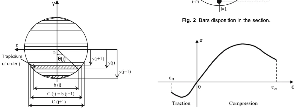
3. Modeling of the Circular Section
3.1 Discretization of the Concrete Section
The concrete section was considered as a succession of trapeziums. Each trapezium was defined by the dimensions of its lower and upper base (bj,bj?1) and their ordinates (yj,
yj?1), relative to the reference axis passing through the center
of gravity of the section (Kachi et al.2014), see Fig.1. The integration process is numerical, it is necessary to express the widths and the ordinates of the trapeziums consistent with the numerical calculation relations.
Hence for the trapezium of order j; the ordinate and the width of the base are expressed respectively by Eqs. (2) and (3). The trapezium width at an ordinatey(j?1) is given by Eq. (4).
y jð Þ ¼ ðD jð 1Þ=NeÞ D
2 ð2Þ
b jð Þ ¼Dsinhð Þj ð3Þ
C jð Þ ¼b jð þ1Þ ð4Þ
wherehð Þ ¼j ar cosjDy jð Þ=2j:
3.2 Definition of the Position of the Bars
The section of each bar is concentrated at its center of gravity; it is indicated by its ordinate on the y-axis (see Fig.2). For a bar of the order i, its ordinate is calculated by Eq. (5).
yað Þ ¼ i ðD=2d0Þcosðði1Þ cÞ ð5Þ
wherec¼2P Nbt.
4. Calculation of Internal Forces
The stress at a point of the section is related to the deformation by the corresponding material behavior law;
r=u (e) see Fig.3. The value of the function u (e) was considered zero beyond the compression and tension strength material, respectively for deformations ecuand ert.
Trapèzium
of order j
y
o θ(j) z
b (j)
C (j) = b (j+1) C (j+1)
y(j+1) y(j)
y(j=1)
Fig. 1 Concrete section modeling.
γ Bar of
ordre i ya(i=1)
y
z
ya(i=2)
i=1
i=2 i=m
Fig. 2 Bars disposition in the section.
The calculation was then carried out in the nonlinear elas-ticity; taking into account the actual behavior of the various materials, some details are given in (Bouafia et al. 2000, Adjrad et al. 2015). The internal efforts (Nint,Mint) devel-oped by the deformations (du, dw) are related by the fol-lowing formulas (Eq. (6)):
Nint¼
RR
rdydz¼RRu dð uþdwyÞ dydz;
Mint¼
RR
rydydz¼RRu dð uþdwyÞ ydydz
ð6Þ
While noting by b(y) the section width to an ordinate y, then the Eq. (6) became:
Nint¼RRu dð uþdwyÞ b yð Þ dy
Mint¼RRu dð uþdwyÞ yb yð Þ dy
ð7Þ
The Eq. (7) can be written in the matrix form as follows:
Nint
Mint
du;dw
ð Þ ¼
Z
u dð uþdwyÞ 1
y bðyÞ dðyÞ ð8Þ
5. Practical Calculation of Internal Forces
5.1 In the Concrete and the Fiber Concrete
Taking into account the Eq. (1), the relationship (Eq. (8)) is rewritten in the following form (Eq. (9)); this one gives the internal forces in concrete and in the fiber concrete.
Nint
Mint
du;dw
ð Þ ¼
Z 1
y ubð Þ e bðyÞ dðyÞ ð9Þ
In the trapezium of order j, integration intervals, corresponding to each segment of the concrete constitutive law, are then defined by boundaries whose calculation involves comparing trapezium extreme fibers deformations at the orderjof ordinateyj,yj?1in the particular strain of the concrete behavior law. These deformations are given by the following expressions:
ej¼duþdwyj and ejþ1¼duþdwyjþ1 ð10Þ
5.2 In the Reinforcing Bar
Similarly, the reinforcement bar strain ei, at order i, is compared to the particular strain of steel behavior law that corresponds to it in order to define the termucorresponding to the straine.
Convergence test On N, M, δu et δw Test of rupture
End det Φt>0
Output calculaon result Yes Yes Yes
(
)
(
(
)
)
⎥ ⎦ ⎤ ⎢ ⎣ ⎡ δ δ δ δ ⋅ δ δ Φ ⎥ ⎦ ⎤ ⎢ ⎣ ⎡ δ δ ⎥ ⎦ ⎤ ⎢ ⎣ ⎡ δ δ 1 -i 1 -i int 1 -i 1 -i int 1 -i 1 -i 1 -1 -i 1 -i w , u M -M w , u N -N w , u t + w u = w uInput the original data
(or
from i=1 to Nbt Inializaon: δu=N/ES, δw=M/EI
Buckle on the secon number
Calculate: Nint, Mint and Φt
Calculate : Nint, Mint and Φt
Connue No
No
No i=i+1
Fig. 4 Calculus method flowchart for loading curves establishment.
N
M P (N, M)
No No
Yes
δu=ε0, δw=0
Calculaon of detΦt (δu, δw)
δw=δw+Δδw
i=i+1, δu=δu-Δδu, δw=0
Δw=Δw/2
N=N(i), M=M(i) det Φt>0
δu<εu No
Yes
Yes
Output calculaon result
End
Δw < precision sought
Fig. 6 Boundary curve establishment flowchart.
Table 1 Characteristics of concrete mechanical properties; C25 and C50.
fcj
(MPa)
ftj
(MPa)
Ebo
(MPa)
Parameter of the Sargin law ert e0 ecu
Kb k
0 b
25 2.1 32,164 2.316 1.316 -0.05 0.018 0.0035
50 3.6 40,524 1.378 0.378 -0.05 0.017 0.0035
Table 2 Characteristics of steels mechanical properties.
Ea(MPa) re(MPa) eu rr(MPa)
200,000 400 0.01 400
Fig. 7 Abacus giving the number of T25 bars for a circular section. (D=50 cm),fcj=25 MPa.
For the reinforcement bar at order i, the internal forces are expressed by Eq. (11):
Nint¼AaiuaðeiÞ
Mint¼AaiuaðeiÞ yai
ð11Þ
The Eq. (11) can be written in the matrix form as follows:
Nint
Mint
du;dw
ð Þ ¼X 1
yai
uaðduþdwyaiÞ Aai
ð12Þ
6. Establishment of Loading Curves
These curves permit to observe the beam section behavior in nonlinear elasticity until rupture. Of course, it is not possible to represent, directly, on the plan a function with two variables, so the problem is reduced to a single variable. Thus, two representations are possible.
– The first one, it’s about to find a Nvalue (axial force), and for anyMivalue; deformations balancing efforts (N,
Mi). Then the loading curveM=f(dw) is deducted. – The second is to find aMvalue (bending moment), and
for anyNivalue; the deformations balancing efforts (Ni,
M). Then the loading curve N=f(du) is deducted. The Flowchart method is given in Fig.4.
7. Establishment of the Interaction Curve
7.1 Theoretical Explanations
The behavior curves N=f(du) and M=f(dw) pass through a maximum in points (M, Nmax) and (N,Mmax), respectively. By wearing into the plan,Mmaxvalues for all values ofN, a curveN=f(Mmax), which is the field limit curve of permissible stresses for the considered section, is obtained. The resulting field is delimited by a curve called the resistance boundary curve for this section (see Fig.5). The presence of point steel in section induces operator U
none derivability points (the operator who allows the pas-sage of deformations to efforts that they develop) in the field of admissible deformations by the transverse section. These Points are characterized by the steels rupture. Either the current deformation of the tense reinforcement, then:
eai eu ð13Þ
7.2 Calculation Algorithm
Deformation values are initialized by those that corre-spond to simple compression du=e0, dw=0 (the limit compression of the section), ending with values du=eu,
dw=0; corresponding at steel tensile limit, certainly pass-ing by the composed bendpass-ing of the section. The method of resolution is given by Fig.6.
8. Application to the Reinforced Concrete
8.1 Influence of the Steel Bars Number
To illustrate the reliability of the program developed in this study, the calculation for a circular section of 50 cm diam-eter with steel bars T25 (/a=25 mm) is presented. Two Fig. 9 Influence of the concrete compressive strength.
Fig. 10 Superposition of curves (M, N) for both feE40 and feE50 steels.
classes of concrete strength, C25 and C50 are used and their main characteristics are summarized in Tables1and2. Also, the real behavior laws for concrete and steel were adopted. Figures7 and 8 represent interaction axial effort N and bending momentM curves for two classes of the concrete: C25 and C50. For values ofNandMknown, the number of bars is directly read on these abacuses.
8.2 Influence of Concrete Strength Characteristics
For the same section of diameter 50 cm reinforced with T25 bars; the calculation, while varying the concrete
characteristic of 25 and 50 MPa, has been performed. Curves obtained (with 10 bars of diameter/a=25 mm) for the two resistances are superposed on Fig.9.
The difference between the two curves is important in the compressions field. Indeed, the influence of the concrete resistance is felt at the compression level; behavior in compression is described by the Sargin law. But the contri-bution in traction remains weak; the concrete tensile strength is the order of tenth of its compression resistance.
8.3 Influence of the Steel Yield Stress
Calculation is carried out for two yield stresses (400 and 500 MPa). The superposition is given in the Fig.10. There is a translation of the curve due to the symmetrical behavior of steel.
8.4 Influence of the Tense Concrete Participation
The contribution of the tense concrete still low compared to the all section behavior. Compared to the calculation without tense concrete, its influence is much felt, rather, in the case of simple bending (see Fig.11).
8.5 Comparing the Behavior According
to the Conventional Relationships (BAEL)
Figure11shows the curves, normal force versus bending moment, for the values from a conventional calculation (BAEL) for the calculated values without taking into account tense concrete and for the values with tense concrete. The comparison of these curves clearly shows the corresponding surface to the introduction of safety factors considered in the conventional calculations.
9. Application to Steel Fibers Reinforced
Concrete
9.1 Confrontation with Experimental Results
The nonlinear modeling of the circular section, considered in this work, was validated on piles whose experimental Table 3 Concrete mechanical properties.
fcj(MPa) ftj(MPa) Ebo(MPa) ert e0 ecu
BFAC 47.6 2.94 38,180 -0.05 0.0021 0.0035
BFON 47.7 2.94 38,180 -0.05 0.0021 0.0035
Table 4 Fibers mechanical properties.
Lf(mm) w(%) Diameter (mm) Ea(MPa) eu Configuration
BFAC 60 0.31 1 200,000 0.074 Hooked fibers
BFON 60 0.31 1 200,000 0.074 Undulated fibers
Fig. 12 Comparison of calculation with experimental results (BFAC).
Fig. 13 Comparison of calculation with experimental results (BFON).
Table 5 Characteristics of mechanical properties of fibers under study.
Lf(mm) w(%) Diameter (mm) Ea(MPa) re(MPa) eu Configuration
study is performed at CEBTP (Zhang1991). The Sargin law is used to describe the fiber reinforced concrete compression behavior. The relations proposed by Bouafia et al. (2002) were used for traction.
The piles have a diameter of 500 mm and are subject to combined bending. The normal compression force is 1370 kN (applied using external prestressing). The first type of piles is hooks fibers reinforced; it is noted BFAC. The second type of piles is reinforced by corrugated fibers; it is noted BFON. The same percentage of fibers is used (0.31 % by volume). The mechanical properties of concrete and fiber are given, respectively, in Tables3and4. The comparison of calculation with experimental results is shown in Figs.12and13.
The test/calculation ratio is close to 1 in the case of the bending moment. Against by, in the case of ultimate curves, this ratio varies between 0.90 and 1.09. This may be due to using the tangent method to the resolution; it sometimes has some convergence problems in the vicinity of the maximum curve. However, the calculation is satisfactory for a per-centage of fiber equal to 0.31 %.
9.2 Confrontation Between Reinforced and Steel Fibers Concrete
Fibers studied are provided with hooks, type ‘‘DRAMIX’’, their main characteristics are described in Table5. Behavior
curves are calculated for two fiber lengths (30 and 50 mm) and three percentages (0.5–1 and 1.5 %). Results and com-parisons between different parameters are given in Figs.14, 15and16.
9.3 Discussion
The percentage of fibers positively influences the steel fibers reinforced section behavior; this contribution of resistance is more important in bending and in tension, unlike in the compression. Curves (Fig.14) show clearly that the allowable compressive stress remains unchanged with fibers percentage variation, this confirms that the steel fibers are rather effective in traction.
The fiber length slightly increases resistance: the length of anchoring thereof in the concrete mass is greater. It then enables better sewing the crack.
By cons, it is not a substitute compared to traditional reinforcement in structural elements (see Fig.16). However, they are used in thin and slabs elements and also to the strengthening and repair (in the form of the shotcrete).
10. Conclusion
The developed software allows to draw abacuses directly giving the bars number necessary to implementing according to the external forces applied and thus to predict the breaking of circular sections. Indeed, the calculation is often tedious for this type of sections. In addition, the calculation methods are often approached. The presented method in this paper uses the actual behavior of different materials (concrete, steel and fiber concrete).
A confrontation is performed with respect to the calcula-tion according to BAEL rules, showing the influence of safety factors. The influence of the fibers is also taken into account. Finally, a confrontation between the reinforced concrete and the fiber concrete (in equivalent percentage) shows the importance and necessity to use steel rebar. Fig. 14 Circular section (D=50 cm) reinforced with steel
fibers in lengthlf=30 mm.
Fig. 15 Influence of the fiber length.
The interest of the developed program is the ability to modify a number of parameters while getting quickly results, this allows studying any section. Therefore, it may be a very practical tool for engineers calculators seen its ease of use.
Open Access
This article is distributed under the terms of the Creative Commons Attribution 4.0 International License (http://creativecommons.org/licenses/by/4.0/), which per-mits unrestricted use, distribution, and reproduction in any medium, provided you give appropriate credit to the original author(s) and the source, provide a link to the Creative Commons license, and indicate if changes were made.
References
Adjrad, A., Bouafia, Y., Kachi, M. S., & Dumontet, H. (2015). Modeling of externally prestressed beams until fracture in non linear elasticity. Applied Mechanics and Materials, 749, 379–385.
Bonet, J. L., Baros, M. H. F. M., & Romero, M. L. (2006). Comparative study of analytical and numerical algorithms for designing reinforced concrete sections under biaxial bending.Computers & Structures, 84, 2184–2193. Bouafia, Y., Kachi, M.S., & Foure´, B. (2000). Numerical
modeling of the behavior of steel fiber reinforced concrete. In Proceedings of the II international conference on cement and concrete technology in the 2000s (Vol. 2, pp. 582–591) Istanbul, Turkey.
Bouafia, Y., Kachi, M.S. & Foure´, B. (2002).Relation stress
-strain in the case of steel fiber reinforced concrete. In ESKA (Eds.Annales of ITB), No 3.
Choa, C. G., & Kwonb, M. (2008). Prediction of non linear bending behavior for FRP Concrete beams based on multi-axial constitutive laws. Engineering Structures, 30, 2311–2320.
Daunys, M., & Rimovkis, S. (2006). Analysis of circular cross-section element, loaded by static and cyclic elastic-plastic pure bending. International Journal of Fatigue, 28, 211–222.
Ding, Y., Zhang, F., Torgal, F., & Zhang, Y. (2012). Shear behavior of steel fibre reinforced self-consolidating con-crete beams Based on the modified compression field the-ory. Composite Structures, 94, 2440–2449.
Eurocode 2. (1992). Design of concrete structures Part 1-1: General rules and rules for buildings. ENV 1992-1-1, NF P 18 711.
Grelat, A. (1978). Nonlinear behavior and stability of indeter-minate reinforced concrete frames, Doctoral thesis, University Paris VI, Paris, France.
Islam, M. S., & Shahria, A. (2013). Principal component and multiple regression analysis for steel fiber reinforced con-crete (SFRC) beams. International Journal of Concrete Structures and Materials, 7(4), 303–317.
Kachi, M. S., Bouafia, Y., Saad, M., Dumontet, H., & Bouhrat, S. (2014). Contribution to the calculation of reinforced concrete circular sections by discrete reinforcement. Inter-national Journal of Engineering and Technology, 6(1), 38–42.
Liang, Q. Q., & Fragomeni, S. (2009). Non linear analysis of circular concrete-filled steel tubular short columns under axial loading. Journal of Constructional Steel Research, 65, 2186–2196.
O¨ zcan, D. M., Bayraktar, A., Sahin, A., Haktanir, T., & Tu¨rker, T. (2009). Experimental and finite element analysis on the steel fiber-reinforced concrete (SFRC) beams ultimate behavior. Construction and Building Materials, 23, 1064–1077.
Ren, W., Sneed, L. H., Gai, Y., & Kang, X. (2015). Test results and nonlinear analysis of RC T-beams strengthened by bonded steel plates. International Journal of Concrete Structures and Materials., 9(2), 133–143.
Ronagh, H. R., & Baji, H. (2014). On the FE modeling of FRP-retrofitted beam-column subassemblies. International Journal of Concrete Structures and Materials, 8(2), 141–155.
Rules: BAEL91 revised 99, technical design rules and calcu-lation of works and structures reinforced concrete, according to the limit states method.
Sorensen, C., Berge, E., & Nikolaisen, E. B. (2014). Investi-gation of fiber distribution in concrete batches discharged from ready-mix truck. International Journal of Concrete Structures and Materials, 8(4), 279–287.
Tadepalli, P. R., Dhonde, H. B., Mo, Y. L., & Hsu, T. T. C. (2015). Shear strength of prestressed steel fiber concrete I-beams.International Journal of Concrete Structures and Materials, 9(3), 267–281.