N O T E
Shear resistance and failure modes of nailed joints loaded
perpendicular to the grain
Kei Sawata•Yosuke Shigemoto• Takuro Hirai• Akio Koizumi• Yoshihisa Sasaki
Received: 8 August 2012 / Accepted: 5 December 2012 / Published online: 20 December 2012 ÓThe Japan Wood Research Society 2012
Abstract Shear tests were conducted on nailed joints in wood that were loaded perpendicular to the grain; these joints had 21 specifications depending on different com-binations of wood species, nail dimensions, number of nails, and edge distances of the main members, and their effects on the shear resistance of the nailed joints were also investigated. The nailed joints with CN75 nails had higher initial stiffness than the joints with CN50 nails, provided the initial stiffness of nailed joints connected with 3 or 5 nails was not always a simple product of the number of nails and the initial stiffness of nailed joints connected with a nail, and instead depended on the combination of wood species of the main member and nail dimensions. When the edge distance decreased, the maximum load and energy capacity decreased, thereby affecting the energy capacity. The maximum load of the nailed joints with CN75 nails may be smaller than those with CN50 nails depending on the combination of wood species and nail dimensions. When the edge distance of the nailed joints was less than 26 mm, the energy capacity of the nailed joints with CN75 nails was less than or similar to those with CN50 nails.
Keywords Wood speciesEdge distanceNumber of nails Nail dimension
Introduction
Nailed joints are the most commonly used joints in wooden houses, and they show shear resistance to lateral force. The nailed joints under lateral force are designed to avoid the brittle failure of wood while designing timber joints. It is known that split failures in nailed joints loaded perpen-dicular to the grain are affected by less thick wood, less spacing between nails, less edge and end distances, and wood species.The standard for structural design of timber structures—edited by Architectural Institute of Japan [1]— specifies that edge and end distances and spacing of nails must be equal to or greater than the minimum required for the design of nailed joints. In this standard, the allowable shear strength of nailed joints without split failure of members is exhibited, and the same values regardless of loading direction to the grain are shown. Although nailed joints with sufficient edge and end distances are preferable, it is difficult to always ensure this during the actual con-structions of wooden houses. Because the width of the common frame members used in wooden houses are sub-stantially fixed, less edge distance is often observed in the actual panel–frame joints. Therefore, it is important to accumulate the data regarding the nailed joints failed by split of members under lateral force if consideration is given to the nailing conditions in the actual construction of wooden houses.
Numerous studies have been performed to investigate the shear resistance of nailed joints. Most reports have focused on nailed joints parallel to the grain [2–6], and only a few studies have investigated the perpendicularly Part of this report was presented at the 61st Annual Meeting of the
Japan Wood Research Society, Kyoto, May 2011; and the Annual Meeting of the Architectural Institute of Japan, Tokyo, August 2011.
K. Sawata (&)Y. ShigemotoT. HiraiA. Koizumi Y. Sasaki
Research Faculty of Agriculture, Hokkaido University, N9 W9, Sapporo 060-8589, Japan
e-mail: [email protected]
Y. Shigemoto
nailed joints [2,4,7,8]. In particular, the collected data for split failures in nailed joints loaded perpendicular to the grain are insufficient. In this study, we have investigated the effects of wood species, nail dimensions, number of nails, and edge distances on the shear resistance of nailed joints loaded perpendicular to the grain.
Materials and methods
Specimens
The shear resistance of nailed joints loaded perpendicular to the grain was determined from two wood species for main member, which were low and high density of struc-tural softwood members, two thicknesses of side member, and two nail sizes. The main members of the nailed joints were prepared from solid lumbers of Sugi (Cryptomeria japonica) and Douglas fir (Pseudotsuga menziesii) whose cross-sections were more than 100 mm9100 mm. The average density of Sugi and Douglas fir were 353 kg/m3 (standard deviation 38.4 kg/m3) and 541 kg/m3 (standard deviation 35.3 kg/m3), respectively. The average moisture contents of Sugi and Douglas fir were 13.2 % (standard deviation 0.365 %) and 14.2 % (standard deviation 0.651 %), respectively.
Side members with thicknesses of 12 and 24 mm were prepared from Larch plywood. The 12-mm-thick plywood, which was constructed from four-ply, and the main mem-ber were connected with a CN50 nail having a diameter of 2.87 mm, length of 50.8 mm [9,10], and the average yield point of 687 N/mm2, which was obtained experimentally from the tensile stress–strain relationships. The 24-mm-thick plywood, which was constructed from nine-ply, and the main member were connected with a CN75 nail having a diameter of 3.33 mm, length of 76.2 mm [9,10], and the average yield point of 699 N/mm2. The ratio of nail length in main member to nail diameter, which effects on the maximum load and energy capacity [6], was 13.2 and 13.6 for the nailed joints with CN50 and CN75 nail, respec-tively. The combination of thickness of side member and nail was determined so that its ratio was similar. The average density of the 12-mm- and 24-mm-thick plywood were 554 kg/m3 (standard deviation 20.6 kg/m3) and 524 kg/m3 (standard deviation 33.3 kg/m3), respectively. The average moisture contents of the 12-mm- and 24-mm-thick plywood were 10.2 % (standard deviation 1.12 %) and 10.3 % (standard deviation 0.954 %), respectively.
The predrilled hole for nailing was not located in the main and side members. The nails were hammered mod-erately to ensure a slight gap to avoid initial friction between the main and side members [6].
A nailed joint specimen that was loaded perpendicular to the grain is shown in Fig.1. The number of nails was 1, 3, and 5. The standard for the structural design of timber structures [1] specifies that the end distance and spacing between the nails of nailed joints loaded perpendicular to the grain must be equal to or more than 10 times the nail diameter. The end distance was 40 mm and the spacing between the nails was 100 mm which was the minimum value of the actual panel–frame joints of wooden houses [11,12]. Both of the end distance and spacing between the nails satisfied the standard.
To investigate the shear resistance of the actual nailed joints, the present study determined the edge distance in consideration of the nailing conditions of actual conven-tional wooden shear walls in Japan instead of the integral multiples of the nail diameter. When plywood is nailed to
52 e2
100
40 50
35
R11 180
t
100<
35
65< [Unit: mm]
: Grain to the direction
Center line
(a) Side view of nailed joints (b)Front view of nailed joints (n = 1)
52 e2 40 50
80
R11
Center line
(c) Front view of nailed joints (n = 3)
100
52 e2 40
50
180
R11
Center line
(d) Front view of nailed joints (n = 5) 100
Nail
Nail
Nail Nail
Plywood
Main member
50 50 30
40
2- 13
4- 13
4- 13
Fig. 1 Configuration of nailed joint specimen.e2edge distance of the
main member: 13 or 26 mm,tthickness of plywood: 12 or 24 mm,
lumber of wooden shear walls, the edge distance of the main member is normally a quarter of the lumber width; however, the distance is sometimes shortened to obtain large margins for the plywood. Therefore, the edge dis-tance was set to 13 and 26 mm, and they corresponded to 1/8 and 1/4, respectively, of the width of a 105-mm square lumber, which is the most common lumber dimension in conventional wooden houses in Japan. The standard [1] specifies that the edge distance of nailed joints perpendic-ular to the grain should not be less than 8 times the nail diameter. The edge distance in this study did not meet the standard except when the nailed joints had edge distance of 26 mm and CN50 nail was used. An outline of the nailed joint specimens and the ratio of edge distance to nail diameter are shown in Table1. The nailed joints had 21 specifications and shear tests of the nailed joints were conducted on 6 specimens per specification.
To avoid restriction of free crack propagation originated from the nail holes, the main members with round
end-notches with a radius of 11 mm were used in this study (Fig.1).
Test methods
Figure2 shows the configuration of the nailed joint tests. The main member was held by two steel blocks. The loading direction was perpendicular to the grain for the main member and parallel to the grain for the plywood face veneer.
The relative slips between the main and side members of the nailed joints connected with 1 and 3 or 5 nails were measured by two and three displacement transducers, respectively. One or two displacement transducers were located in the front side of nailed joints, and one dis-placement transducer was located in the back side, see Fig.2. The relative slip for loading procedure was used the values measured by the displacement transducers located in the front side. When the joints connected with 3 or 5 nails, that relative slip was the average values of two displace-ment transducers. The load was applied up to a relative slip of 1 mm, and subsequently, reduced to 0 kN. This loading procedure was repeated to produce relative slips of 2, 3, and 4 mm. The slip level was determined from the load– slip curves obtained from the preliminary monotonic loading tests of the nailed joints S26–50 and D26–50 whose nailing conditions satisfied the standard [1]. The load was then monotonically increased and the tests were terminated when the load decreased to 50 % of the maxi-mum load. The nailed joints were loaded at the rate of relative slip, which was the average slip on the centerline of nailed joint, of between 0.02 and 0.08 mm/s [13]. Table 1 Outline of the nailed joint tests
Symbols Main member Nail Number of nails
Species e2(e2/d)
S13–50 Sugi 13 mm (4.5) CN50 1, 3, 5
S13–75 Sugi 13 mm (3.5) CN75 1, 3, 5
S26–50 Sugi 26 mm (9.1) CN50 1, 3, 5
S26–75 Sugi 26 mm (6.9) CN75 1, 3, 5
D13–50 Douglas fir 13 mm (4.5) CN50 1, 3, 5
D26–50 Douglas fir 26 mm (9.1) CN50 1, 3, 5
D26–75 Douglas fir 26 mm (6.9) CN75 1, 3, 5
e2edge distance,dnail diameter
16 bolt
Plywood
Main member Nail
Loading direction after cyclic tests
Displacement transducer
Transducer bed
Steel block
(b) Side view of nailed joints
(a) Front view of nailed joints
12 bolt Steel plate
Results and discussion
Failure mode
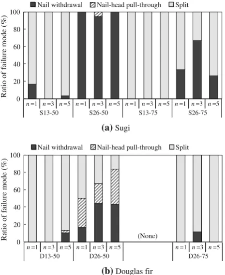
There were no specimen failures due to splitting from the notch. The failures of the nailed joint specimens can be classified into three modes: nail withdrawal, nail-head pull-through, and main-member splitting. Figure3 shows the failure modes of the nailed joints. For the symbols in Fig.3, see Table1. The nailed joints with edge distance of 13 mm (S13–50, S13–75 and D13–50 in Table1) were almost broken by the main-member splitting regardless of the combination of the wood species and nail dimensions. In the case of the nailed joints with the edge distance of 26 mm, most of the nailed joint S26–50 exhibited nail withdrawal, whereas D26–50 exhibited all three failure modes. The nailed joint S26–75 was broken by either nail withdrawal or main-member splitting, whereas D26–75 was broken only by main-member splitting.
Envelop load–slip curve
In the case of the joints connected with 3 or 5 nails, two displacement transducers located in the front side did not
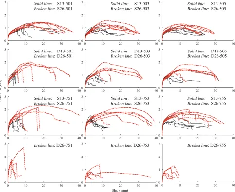
always indicate same values during the nailed joint tests, because the shear resistance of each joint of the joints connected with multiple nails would differ with the nailing position of the main and side members. Therefore, the average slip on the centerline of nailed joint was calculated from the average slip in the front side and the slip in the back side. The following slips indicate the average slip on the centerline of nailed joint. Figure4shows the envelope load–slip curves of the nailed joints that were loaded per-pendicular to the grain. The load in Fig.4 is given by the values divided by the number of nails. Nailed joints with the edge distance of 26 mm had higher loads than those with the edge distance of 13 mm, and this was particularly evident when the main member was Douglas fir. When the nailed joints were broken by nail withdrawal or nail-head pull-through, the load of the nailed joints gradually decreased after reaching a maximum load. The load of the joints connected with a nail that broke by the main-member splitting significantly decreased after the maximum load, whereas the load of the joints connected with 3 or 5 nails demonstrated a stepwise decrease. In the case of almost all the nailed joints D26–75, the load decreased before the 10-mm slip.
The initial stiffness, maximum load, and energy capacity up to 80 % of the maximum load over the maximum load were calculated from the envelope load– slip curves as shown in Fig.5. The initial stiffness values of the joints connected with 1, 3 or 5 nails were calcu-lated using the average yield slip of joints connected with a nail. The yield slips of the joints connected with a nail were determined as follows. In the envelope load– slip curves, a straight-line (line I in Fig. 5) was drawn through the points on the curves corresponding to 10 and 40 % of the maximum load. The second straight-line (line III) has the same slope as the line (line II) passing through the points corresponding to 40 and 90 % of the maximum load, and it is tangent to the curve. The load (Pi) corresponding to the intersection of the first and second straight-lines (lines I and III) is obtained first, and the slip on the curve corresponding to its load is then obtained. This slip is defines as the yield slip (Dy) [14]. The average yield slip of each joint connected with a nail is calculated, and the load on the curves corresponding to the average yield slip is defined as the yield load. The line passing through the origin and the coordinates of the yield load and the average yield slip is defined as the initial stiffness (Ks). In the case of the joints connected with 3 or 5 nails, the yield load is defined as the load on the curves corresponding to the average yield slip of the joints connected with a nail of the same specifications except for the number of nails. The initial stiffness is calculated using its yield load and average yield slip as 0
20 40 60 80 100
Ratio of failure mode (%)
Nail withdrawal Nail-head pull-through Split
0 20 40 60 80 100
Ratio of failure mode (%)
Nail withdrawal Nail-head pull-through Split
(None)
(b) Douglas fir
(a) Sugi
n=1 n=3 n=5 n=1 n=3 n=5 n=1 n=3 n=5 n=1 n=3 n=5
S13-50 S26-50 S13-75 S26-75
n=1 n=3 n=5 n=1 n=3 n=5 n=1 n=3 n=5
D26-75 D26-50
D13-50
Fig. 3 Failure modes of nailed joints loaded perpendicular to the grain. For thesymbols, see Table1.aNailed joints with Sugi as the main member.bNailed joints with Douglas fir as the main member.
described above. This method is adopted to investigate the effects of nailed joint specifications on the accumu-lation of load in small slip.
Shear resistance
Table2shows the yield slip of joints connected with a nail and Fig.6shows the initial stiffness divided by the number of nails (K/n). The nailed joints with the edge distance of 13 mm showed higher values of K/n than those with the edge distance of 26 mm. Linear load–slip behaviors of nailed joints were not observed even though the slip was small (Fig.4). Because the yield slip of the former was smaller than that of the latter, the values of K/n of the former were evaluated as higher than those of the latter. These results would be caused by the evaluation method described above. The values ofK/nof the nailed joints with the CN75 nail were larger than those with the CN50 nail regardless of the wood species and edge distance. When Sugi was used as the main member of the nailed joints, the values of K/n showed approximately identical values regardless of the number of nails. In the case of the nailed
0 1 2 3
0 10 20 30 40
0 1 2 3
0 10 20 30 40
0 1 2 3
0 10 20 30 40
0 1 2 3
0 10 20 30 40
0 1 2 3
0 10 20 30 40
0 1 2 3
0 10 20 30 40
0 1 2 3
0 10 20 30 40
0 1 2 3
0 10 20 30 40
0 1 2 3
0 10 20 30 40
0 1 2 3
0 10 20 30 40
0 1 2 3
0 10 20 30 40
0 1 2 3
0 10 20 30 40
Slip (mm)
Load /
n
(kN)
Solid line: Broken line:
S13-501 S26-501
Solid line: Broken line:
S13-503 S26-503
Solid line: Broken line:
S13-505 S26-505
Solid line: Broken line:
D13-501 D26-501
Solid line: Broken line:
D13-503 D26-503
Solid line: Broken line:
D13-505 D26-505
Solid line: Broken line:
S13-751 S26-751
Solid line: Broken line:
S13-753 S26-753
Solid line: Broken line:
S13-755 S26-755
Broken line: D26-751 Broken line: D26-753 Broken line: D26-755
Fig. 4 Relations between load divided by number of nails and slip of nailed joints. For thesymbols, see Table1
0.8Pmax Pmax
0.4Pmax
0.1Pmax
0.9Pmax
Dy Pi
Load
Slip
Ks
Fig. 5 Method of evaluating shear performances of nailed joints.
Pmaxmaximum load,Piload corresponding to the intersection of lines
joints D13–50 and D26–50, the number of nails only slightly affected the values ofK/n; however, in the case of the nailed joint D26–75, the values of K/n differed sig-nificantly with the number of nails (Fig.4).
Figure7 shows the maximum load divided by the number of nails (Pmax/n). The values of Pmax/n of the nailed joints with the edge distance of 13 mm were smaller than those with the edge distance of 26 mm (Figs.4, 7); moreover, the nailed joints S13–50, S13–75 and D13–50 were 0.78–0.83, 0.65–0.74, and 0.59–0.68 times as large as
S26–50, S26–75 and D26–50, respectively. The values of Pmax/nof the nailed joints S13–75 and S26–75 were larger than those of S13–50 and S26–50, respectively. Further, in the case of the joints connected with 3 or 5 nails with Douglas fir as the main member, this result was the opposite: the values ofPmax/n of the nailed joint D26–75 were smaller than those of D26–50 (Figs.4,7). In the case of the nailed joints with Sugi as the main member, the average values ofPmax/nslightly decreased as the number of nails increased; however, the differences between the joints connected with a nail and the joints connected with 3 or 5 nails were not significant at the 95 % confidence level. In the case of the nailed joints with Douglas fir as the main member, when the nailed joint D26–75 was used, the values ofPmax/nvaried with the number of nails. The edge distance of 26 mm was 6.91 times as large as the nail diameter of the CN75 nail. This was 4.08 mm smaller than the values given by the standard [1]. However, when the CN75 nail was nailed in Douglas fir, the initial stiffness and maximum load of joints connected with 3 or 5 nails were not a simple product of the number of nails multiplied by the values for joints connected with a nail. This indicates that the load in small slip, which is a range of the initial stiffness, and the maximum load may not be proportional to the number of nails and may instead depend on the combination of wood species and nail dimensions.
Figure8shows the energy capacity divided by the number of nails (E/n). In the case of the nailed joints with an edge distance of 13 mm, the values ofE/nslightly increased as the number of nails increased, because the load of the joints con-nected with 3 or 5 nails did not rapidly decrease after the main member-splitting (Fig.4). However, the values ofE/nof the nailed joints with the edge distance of 13 mm were consider-ably smaller than those with the edge distance of 26 mm; moreover, the values ofE/nof the nailed joints S13–50, S13–75 and D13–50 were 0.31–0.46, 0.15–0.30, and 0.12–0.28 times larger, respectively, than those of S26–50, S26–75 and Table 2 Yield slip of nailed
joints connected with a nail Symbols Yield slip (mm)
S13–50 1.11
S13–75 0.82
S26–50 1.82
S26–75 1.60
D13–50 0.59
D26–50 1.56
D26–75 0.55
n = 1 n = 3 n = 5 n = 1 n = 3 n = 5
Sugi Douglas fir 0
0.5 1 1.5 2 2.5
Initial stiffness /
n
(kN/mm)
CN50,e2=13 CN50,e2=26
CN75,e2=13 CN75,e2=26
CN50, e2= 13mm
CN75, e2= 13mm
CN50, e2= 26mm
CN75, e2= 26mm
Fig. 6 Initial stiffness divided by number of nails of nailed joints.
Symbols and bars indicate mean value and standard deviation, respectively.nnumber of nails,e2edge distance
n = 1 n = 3 n = 5 n = 1 n = 3 n = 5
Sugi Douglas fir 0
0.5 1 1.5 2 2.5 3
Maximum load /
n
(kN)
CN50,e2=13 CN50,e2=26
CN75,e2=13 CN75,e2=26
CN50, e2= 13mm
CN75, e2= 13mm
CN50, e2= 26mm
CN75, e2= 26mm
Fig. 7 Maximum load divided by number of nails of nailed joints.
Symbols and bars indicate mean value and standard deviation, respectively.nnumber of nails,e2edge distance
n = 1 n = 3 n = 5 n = 1 n = 3 n = 5 Sugi Douglas fir 0
10 20 30 40 50 60 70
Energy capacity /
n
(kN
mm)
CN50,e2=13 CN50,e2=26
CN75,e2=13 CN75,e2=26
CN50, e2= 13mm
CN75, e2= 13mm
CN50, e2= 26mm
CN75, e2= 26mm
Fig. 8 Energy capacity divided by number of nails of nailed joints.
D26–50. The differences between the nailed joints with the CN50 and CN75 nails were not significant at the 95 % confi-dence level for the nailed joints with Sugi as the main member. In the case of the nailed joints with Douglas fir as the main member, the nailed joint D26–75 had considerably smaller values ofE/nthan D26–50. When the edge distance was not more than 26 mm, the values ofE/nof the nailed joints per-pendicular to the grain with the CN75 nail were either nearly identical with or smaller than those with the CN50 nail. The energy capacity significantly differs with the failure modes of the nailed joints, and there may be large variations depending on the combination of the wood species and nail dimensions.
In the standard [1], the nailed joints with the CN75 nail is exhibited higher allowable shear strength than that with the CN50 nail. However, when the nailing space is under restriction and the nailed joints are loaded perpendicular to the grain, the nailed joints with the CN75 nail did not always have greater shear resistance than that with the CN50 nail.
Conclusions
Shear tests were conducted on nailed joints loaded per-pendicular to the grain; the joints differed according to the 21 specifications based on combinations of different wood species, nail dimensions, number of nails, and edge dis-tances. The results obtained can be summarized as follows. 1. The load–slip curve of the nailed joints that exhibit failure by main-member splitting had a different shape than that for failures by nail withdrawal or nail-head pull-thorough. Further, in the former case, the load was significantly decreased after a maximum load. When the edge distance was small and the CN75 nail was nailed in Douglas fir, main-member splitting occurred easily. 2. The nailed joints loaded perpendicular to the grain
with the CN75 nails had higher initial stiffness than those with the CN50 nails. However, the initial stiffness of the joints connected with 3 or 5 nails was not always a simple product of number of nails and the values for joints connected with a nail, and instead depended on the combination of the wood species of the main member and nail dimensions.
3. The nailed joints loaded perpendicular to the grain with the CN75 nail did not always have a higher maximum load than those with the CN50 nail; the maximum load was sometimes smaller, depending on the combination of wood species and nail dimensions. 4. Energy capacity was significantly affected by the edge distance and exhibited large variations, depending on the combination of wood species and nail dimensions. When the edge distance of the nailed joints loaded perpendicular to the grain was less than 26 mm, the
energy capacity of the nailed joints with the CN75 nail was either slightly different or smaller than those with the CN50 nail.
5. In actual timber structures, it may be rare for nailed joint connected with multiple nails to be wholly loaded perpendicular to the grain. However, that would be most rigorous conditions for nailed joints under lateral force because loading direction perpendicular to the grain is easy to split wood and shear resistance of its nailed joints may significantly decrease by main-member splitting. Therefore, if nailed joints connected with multiple nails to be wholly loaded perpendicular to the grain are confirmed to have sufficiently shear resistance, its specification of nailed joints would be also effective for nailed joints with inclined loading direction to the perpendicular to the grain.
References
1. Architectural Institute of Japan (2006) Standard for structural design of timber structures (in Japanese). Architectural Institute of Japan, Tokyo, pp 266–278
2. Hirai T (1987) Basic properties of mechanical wood-joints1. Load–slip curves of nailed wood-plywood joints (1) (in Japa-nese). Res Bull Hokkaido Univ For 44:1307–1328
3. Kamiya F, Oshiumi S (1989) Lateral loading tests of plywood-lumber nailed joints and proposed allowable lateral capacity (in Japanese). Mokuzai Gakkaishi 35:313–319
4. Hirai T, Ando Y, Ueda K (1991) Lateral resistances and fracture modes of nailed timber joints I (in Japanese). Mokuzai Gakkaishi 37:1157–1166
5. Blass HJ (1994) Characteristic strength of nailed joints. For Prod J 44:33–39
6. Sawata K, Honda K, Hirai T, Koizumi A, Sasaki Y (2010) Effect of member thickness and nail length projecting from main member on shear performance of single shear nailed joints (in Japanese). Mokuzai Gakkaishi 56:317–325
7. Soltis LA, Karnasudirdja S, Little JK (1987) Angle to grain strength of dowel-type fasteners. Wood Fiber Sci 19:68–80 8. Girhammar UA, Bovim NI, Ka¨llsner B (2004) Characteristics of
sheathing-to-timber joints in wood shear walls. In: Proceedings of the 8th world conference on timber engineering, Lahti, Finland, pp 1001–1006
9. Japanese Industrial Standard (2009) Nails (in Japanese). JIS A 5508. Japanese Industrial Standard Association, Tokyo 10. Japanese Industrial Standard (2011) Low carbon steel wires (in
Japanese). JIS G 3532. Japanese Industrial Standard Association, Tokyo
11. Japan Ministry of Land, Infrastructure, Transport and Tourism (1981) Notification No. 1100 of the Ministry of Construction 12. Japan Ministry of Land, Infrastructure, Transport and Tourism
(2001) Notification No. 1541 of the Ministry of Land, Infra-structure, Transport and Tourism