R E S E A R C H
Open Access
Research on the effect of image size on
real-time performance of robot vision
positioning
Desheng Lyu
*, Heyang Xia and Chen Wang
Abstract
In order to improve the real-time performance of visual positioning of the indoor mobile robot, the researchers found that the shape and size of the positioned image have a great influence on the real-time performance of the positioning calculation. In order to verify the conclusion and find the appropriate image shape and size to meet the robot’s visual positioning requirements, this paper adopts four different shapes, such as quadrilateral and circular, and uses SURF algorithm to extract and recognize the features of the image. The effect of image shape and size on real-time localization is studied from two aspects: the localization of different shape models under the same size by the visual robot and the localization of the different shape models by the visual robot. It is found that the accuracy and real time of positioning squares and circles are higher than the accuracy and real time of positioning triangles and hexagons under the same size. And when the image size ratio is between 40 and 60% of the original image, the change of the number of feature points is relatively stable and the number of feature points is moderate. It can improve the real-time performance of mobile robot vision localization under the premise of a certain positioning accuracy.
Keywords:SURF algorithm, Visual localization, Image size, Image shape
1 Introduction
As a high-end electromechanical device integrating a computer system, a control system, a sensing system, a mechanical system, and an electrical system, the robot has a high degree of complexity. The sensor system plays an important role in the entire robot system. The sen-sory system includes a variety of sensors that sense dis-tance, light, temperature, vision, and the like. However, it is impossible to leave the robot vision system to give the robot higher intelligence. The robot vision is to get the image of the environment through a visual sensor and analyze and calculate through the visual processor, and then convert it into a symbol so that the robot can identify the object and determine its position [1]. In the robot vision system, image processing is its core part. In order to improve the quality of the image and reduce the signal-noise ratio, the robot vision system prepro-cesses the acquired image first and then carries out the
recognition and location of the image. The premise of robot vision positioning is target recognition, that is, by collecting and matching feature points, the computer vi-sion can identify the target from the image taken by the CCD camera and track the location after the computer is finished with the feature points to judge the location of the target.
In recent years, mobile robot localization method based on vision system has been widely used in indoor and outdoor environments. Schmid and Mohr [2] propose a rotation invariant feature detector to solve general image recognition problems. Mikolajczyk and Schmid [3, 4] extend the idea and propose Harris-La-place detector with scale invariance, which first ex-tracts the Harris corners from the fixed scale space, then uses the Laplace scaling function to determine whether the scale of the corners is the neighborhood maxima. Harris-Laplace feature points have relatively good scale, affine invariance, and high real-time per-formance. It has been successfully applied to target recognition and other fields. SIFT (scale invariant
* Correspondence:[email protected]
Key Laboratory of Interactive Media Design and Equipment Service Innovation (Ministry of Culture), Harbin Institute of Technology, Harbin, China
feature transform) algorithm proposed by David Lowe is also a popular and successful local feature extrac-tion algorithm [5, 6]. SIFT detects feature points from scale space and then uses gradient blocks to construct feature descriptions. The research shows that the loca-tion of the feature points extracted by SIFT is accur-ate, which has good affine, light invariance, and high real-time performance, and the overall performance is higher than other local feature extraction operators. SIFT algorithm has achieved great success in the field of target recognition and image matching. Although SIFT has great advantages in image feature extraction, the algorithm also has its shortcomings. The algorithm has a large amount of computation, cannot identify and extract accurate feature points for blurred edges or less feature points, cannot clearly identify the edges and outlines, and the extracted points cannot be regis-tered. The accuracy of extraction is not satisfactory.
In view of its shortcomings, Bay, H. and others have improved its computing feature point speed on the basis of SIFT algorithm and formed a fast feature extraction and matching algorithm, SURF (Speeded-Up Robust Features) algorithm [7]. The algorithm improves the speed and stability of computing feature points. To achieve the purpose of improving the speed of comput-ing characteristic points, the Haar wavelet is used in-stead of Gauss filter to integrate the original image. In order to increase the robustness of the feature points, the Hessian matrix is used in the detection of the feature points. At present, the application of SURF algorithm in mobile robot vision localization is more and more exten-sive. Its high efficiency and high stability surpass that of the similar algorithm [8].
At present, many indoor mobile robots are required to deliver objects to designated destinations in a var-iety of environments. When indoor mobile robot is positioned autonomously, it requires high real-time visual localization, but the accuracy of image recogni-tion is not high. Therefore, many scholars have carried out a series of research on improving the real-time performance of SUFT algorithm. Document [9] pro-posed an improved feature descriptor, RIBRIEF, to im-prove the overall real-time performance of the algorithm by combining descriptor index with descrip-tor clustering, based on fast stable feature point ex-traction and logical computation similarity. The experimental results show that compared with de-scriptor BRIEF and SURF algorithm, the image
match-ing algorithm based on RIBRIEF has obvious
advantages in robust real-time performance. At the same time, some researchers put forward that [10] can improve the real-time localization by changing the di-mension of feature points and achieved good results. In addition, studies have also shown that [11]
positioned image shape and image size have a greater impact on the real-time positioning.
In order to verify the conclusion that the image shape and image size have a great influence on the real-time positioning and find the appropriate image shape and size to meet the robot’s visual positioning requirements, in this paper, four different shapes such as normal quadrilateral are used, and the SURF algorithm is used to study the influence of image shape and size on the real-time positioning of the vis-ual robot from the positioning of various shape models under the same size and the positioning of the visual robot to the same shape and different size models.
2 Image feature extraction and stitching algorithm method
2.1 SIFT algorithm
SIFT algorithm was first proposed by Lowe in 1999, and based on this, a feature matching algorithm [12] perfected in 2004, which summarizes the current fea-ture point extraction methods, especially based on techniques with invariant features. The point feature registration algorithm for keeping some invariant scal-ing between translation and rotation is proposed. The algorithm [13, 14] has good stability and registration ability and can handle the matching under the com-plex situations such as rotation scaling, translation, affine, projection, viewing angle, and illumination con-version. It is currently a popular and successful local feature extraction algorithm.
The SIFT algorithm mainly includes two parts: the process of extracting feature points and the process of matching feature points. Among them, the extrac-tion process of SIFT feature points includes four steps: Firstly, the scale-space extremum of the image is detected; then, the feature point direction informa-tion is calculated from the local features of the image, and the SIFT feature description operator of the scale and direction features is finally obtained.
2.1.1 Scale-space extremum detection
The concept of “scale space” is a valid complement
to the famous “image pyramid” concept. Koenderink
and Lindeberg have proved that the Gaussian kernel is the only possible linear scale kernel. The scale space L(x,y,σ) is obtained from the image I(x,y) and
Gaussian kernel convolution G. In order to extract
D xð ;y;σÞ ¼½G xð ;y;kσÞ−G xð ;y;σÞ I xð ;yÞ
¼L xð ;y;kσÞ−L xð ;y;σÞ ð1Þ
In the formula Gðx;y;σÞ ¼ 1 2πσ2e
−ðx2þy2Þ
2σ2 , (x,y) is the
space coordinate;σis the scale space factor.
2.1.2 Accurately determine the location of feature points In order to ensure that extreme points are detected in both the scale space and the two-dimensional image space, Lowe’s algorithm compares the middle detec-tion point with its eight adjacent points of the same scale and the 9 × 2 points of the upper and lower adja-cent scales. After finding the extreme points, those low-contrast points and unstable edge response points need to be removed. An inappropriate Gaussian differ-ence function will result in a larger main curvature at the edges. The main curvature passes through a 2 × 2 Hessian matrix:
H¼ Dxx Dxy Dxy Dyy
ð2Þ
Let σ be the largest eigenvalue and β be the smallest eigenvalue, then
Tr Hð Þ ¼DxxþDyy¼αþβ ð3Þ
Detð Þ ¼H DxxDyy−ðDxyÞ2¼αβ ð4Þ
Letα=rβ, then
Tr Hð Þ2
Detð ÞH ¼
αþβ
ð Þ2
αβ ¼
rþ1
ð Þ2
r ð5Þ
Among them, when TrDetðHðHÞ2Þ<ðrþr1Þ2, it means that the main curvature is under a certain value r. If a point is the maximum or minimum in the DoG scale space, then this point is a feature point of the image in the scale.
2.1.3 Specify the direction parameter of the operator The SIFT algorithm uses the local features of the image to assign SIFT feature points to the reference direction, making the SIFT descriptors rotationally invariant. The SIFT algorithm uses image gradient information to ob-tain the stable direction of the local structure. The fea-ture points are detected in the Gaussian difference pyramid, and the gradient and direction distribution characteristics of the pixels in the 3σ neighborhood window of the Gaussian pyramid image are acquired. After completing the gradient calculation of the feature points, the histogram is used to count the gradient and direction of the pixels in the neighborhood. The for-mula for calculating the mode and direction of each pixel gradient is:
m xð ;yÞ ¼
ffiffiffiffiffiffiffiffiffiffiffiffiffiffiffiffiffiffiffiffiffiffiffiffiffiffiffiffiffiffiffiffiffiffiffiffiffiffiffiffiffiffiffiffiffiffiffiffiffiffiffiffiffiffiffiffiffiffiffiffiffiffiffiffiffiffiffiffiffiffiffiffiffiffiffiffiffiffiffiffiffiffiffiffiffiffiffiffiffiffiffiffiffiffiffiffiffiffiffi L xð þ1;yÞ−L x−ð 1;yÞ
ð Þ2
þ ðL xð;yþ1Þ−L xð ;y−1Þ2
q
ð6Þ
θðx;yÞ ¼ arctanðL xð ;yþ1Þ−L xð ;y−1ÞÞ
L xð þ1;yÞ−L xð −1;yÞ ð7Þ
In formulas 6 and 7, L(x,y) represents a
two-dimensional scale space.
2.1.4 Extracting feature point descriptor
After the key points of the image were detected, a SIFT fea-ture area was determined. In order to enhance the algo-rithm’s ability to resist noise and provide better compatibility for feature matching with positioning errors, the neighbor-hood can be set to a size of 4 × 4. This key point is repre-sented by a 128-dimensional feature vector. In order to remove the effects of illumination changes, the SIFT feature vectors at this time have removed the effects of geometric deformation factors such as scale change and rotation and further normalize the length of feature vectors.
2.2 SURF algorithm
Based on the study of SIFT algorithm, a SURF (Spee-ded-Up Robust Features) algorithm is proposed in docu-ment [15]. The algorithm improves the speed and stability of finding feature points. In order to achieve the purpose of acceleration, it integrates the original image and uses the Haar wavelet derivative instead of the Gaussian filter. The Hessian matrix is used for the ro-bust row algorithm to increase the feature points. The main implementation process includes detection of fea-ture points, description of feafea-ture points, and matching of feature points [16].
2.2.1 Feature point detection
SURF algorithm adds Hessian approximate matrix and integral image when detecting feature points, accumu-lates gray values of original image to obtain integral image, and replaces Gaussian filter in SIFT algorithm with gray integrated value, which can improve the acqui-sition of feature points, and the speed of the calculation has been improved. The definition of the integral image is as follows [17]:
Let X= (x,y) be any pixel on the selected image I(X), then the integral image I∑(X) is the origin of the image on the top left vertex, and the pointX= (x,y) is the sum of all pixels in the rectangular region formed by the lower right vertex.
IPð Þ ¼X X
i≤x
i¼0
Xj≤y
j¼0
I ið Þ;j ð8Þ
sum of the grayscale values in the rectangular region of the integral image, andε=A–B−C+D, whereA,B,C, and D are the vertices of the four corners of the rect-angle, respectively.
The SURF algorithm detects the feature points based on the local maximum or minimum value of the deter-minant of the Hessian approximation matrix. Because the digital image is a two-dimensional discontinuous matrix, the Gaussian convolution smoothing and the
dif-ferential operation are carried out, and the
non-continuous image space point X(x,y) and the scale parameter are σ, the Hessian approximation matrix is defined as follows:
H Xð ;σÞ ¼ Lxx Xð ;σÞ Lxy Xð ;σÞ Lxy Xð ;σÞ Lyy Xð ;σÞ
ð9Þ
where Lxx(X,σ) represents the convolution between the image I(X) taken by the Gaussian second-order partial derivative at any pointX.Lxx(X,σ) andLxy(X,σ) have a similar meaning. In order to improve the computational efficiency of the whole process, Bay and others used
Dxx,DxyandDyyto replaceLxx,Lxy,Lyy, so the deter-minant of the Hessian approximation matrix is obtained, which is
detðHapproxÞ ¼DxxDyy−ðϖDxyÞ2 ð10Þ
In the formula, ω is a weight coefficient, generally taking a value of 0.9. The D function is a differential operation that approximates the digital image through a spatial domain difference. In the SURF algorithm, differentials are approximated by the differences in the horizontal, vertical, and diagonal directions. Ac-cording to the determinant method of the Hessian approximation matrix, the response of any point on the acquired image is calculated and the result is retained, so that different σ response results are ob-tained. Then, the results obtained are subjected to a non-maximum suppression operation so that those extreme points can be selected as candidate feature points. Finally, in order to ensure that the selected feature points are true feature points, using the method of 3D second-order function fitting proposed in literature 18, the method can accurately locate the feature points, thereby obtaining the position of the feature points and information on different sizes.
2.2.2 Feature point description
The premise of feature point description is the main direction calibration of feature points. Make a circular neighborhood of a certain size centered on the fea-ture point and use the Haar wavelet template to process the image in the neighborhood to make the Haar wavelet response in each direction of x and y.
Then, use a sector angle of a circle of a certain size to make a circle around the selected feature point, calculate the sum of the Haar wavelet response vec-tors for all points on the image when the sector is at any angle, and find the largest value of the Haar wavelet response vector. The one that corresponds to this direction is the main direction of the feature point. After defining the main direction, you can build the description vector in the main direction. Centering on the selected feature point, a square neighborhood with a certain length and a side length is used, and the main direction of the determined fea-ture point is set as the direction of the y-axis of the neighborhood of the square. Divide the square
neigh-borhood into multiple sub-regions, use dx and dy to
represent the Haar wavelet response in the x and y
directions in each sub-region, and sum the dx, dy, |dx||dy| in each sub-region. Get a four-dimensional vector V(∑dx,∑dy, ∑|dx| , ∑|dy| ). When the feature point is extracted, the sub-feature vector will be de-scribed, and then, the vector is normalized so that the SUFR descriptor can be obtained.
In order to reduce the influence of intensity and con-trast of the grayscale on the result, the SURF algorithm uses a 4 × 4 × 4 = 64-dimensional vector to describe a feature point and normalize it.
2.2.3 Matching of feature points
LetPA be any point on taken image A, PBbe any point
on taken imageB, and their description sub-vectors are set to DA and DB, respectively. DA(i) and DB(i) are their
ith components, respectively. Then, the distance be-tweenPAandPBis
D PAð ;PBÞ ¼
ffiffiffiffiffiffiffiffiffiffiffiffiffiffiffiffiffiffiffiffiffiffiffiffiffiffiffiffiffiffiffiffiffiffiffiffiffi Xn
i¼1
ðDA ið Þ−DB ið Þ2
s
ð11Þ
Calculate the distance between a pointPA(i) on theA
image and all the points in theBimage according to for-mula (11). Then, according to Lowe’s method used in document 20, complete the matching between SURF fea-ture points.
3 Robot vision system
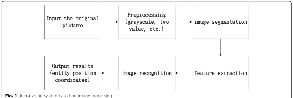
is a robot vision system based on image processing, which shows the whole process of vision system’s image process-ing; input the original image, gray, binary image preprocess-ing, and then image segmentation, feature extraction, later on according to the extracted features for image recogni-tion, and finally according to the recognition results, output the corresponding image position.
In this system, the key technologies of image process-ing involve image segmentation, image recognition and moving object detection and tracking. The algorithms commonly used for image segmentation can be divided into three categories [19]: (1) Threshold-based segmen-tation algorithms, for example, iterative threshold method, bimodal threshold method, histogram threshold method and adaptive threshold method. (2) Edge-based segmentation algorithm; common edge detection opera-tors include the Robert operator, the Laplacian operator, and the Canny operator. (3) Region-based segmentation algorithm; the methods used for image recognition are generally divided into three categories: (1) based on the target geometry model; (2) based on the actual appear-ance effect of the target, such as a histogram method; (3) based on local feature invariance, for example, SIFT and SURF algorithms. Two types of techniques are com-monly used in moving target detection and tracking: (1) use binocular stereo vision technology and (2) use mon-ocular vision system to collect images and detect moving objects according to certain algorithm. The robot vision system in this paper uses a monocular vision system to collect images, uses an iterative threshold method to segment the image, and uses the SURF algorithm to identify and locate the image. The whole process of vi-sion system’s processing is as follows:
3.1 Image grayscale
In the visual positioning process of the robot, the image to be processed recorded by the camera is first subjected to image graying processing. In general, the pixels of a color image are represented by 3 bytes, each byte
corresponding to the R, G, and B components (red,
green, and blue), and the pixels of the converted black and white image represent the gray value by 1 byte. In this paper, we use the weighted average method to
weight-average the three components of the image R
component, G component, and B component with
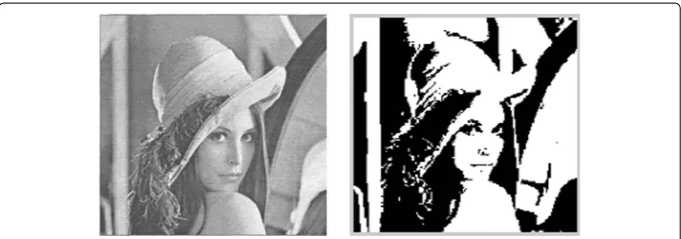
dif-ferent weights. The original image is grayed out. Figure2 shows the effect of the image Lena after graying and binarization.
3.2 Image segmentation
Image segmentation is to divide the image into some meaningful regions and then describe these regions, which is equivalent to extracting the features of some target regions and judging whether there is an inter-esting target in the image. The threshold processing [20] is a region segmentation technique, which divides grayscale into two or more equally spaced or unequal intervals of grayscale intervals based on subjective wishes. It mainly uses the difference between the ob-ject and the background in the image and selects a suitable threshold to determine whether the pixel in the image belongs to the target area or the background area by judging whether the feature attribute of each pixel in the image satisfies the threshold and thus pro-duces the two value image. Because the iterative threshold segmentation method can generate thresh-old dynamically, it is convenient for continuous image processing and has good real-time performance and fast processing speed. Therefore, in this paper, we use iterative method to determine the threshold value, that is, we can automatically calculate the appropriate seg-mentation threshold through the program. Figure 3 is the effect of an iterative segmentation of the image.
3.3 Feature extraction and image recognition
Feature extraction and image recognition are based on image segmentation to extract features and identify the contents of the images. In this paper, we use the method
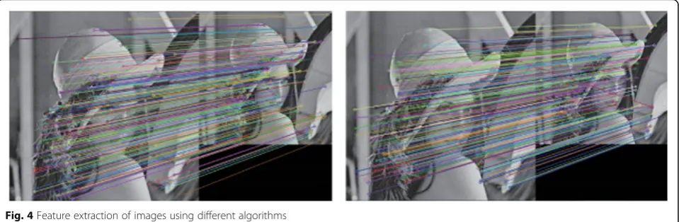
of local feature invariant to identify Lena images. The general process is [21]: Firstly, the integral image of the image is calculated, the candidate points of the feature points are determined by the Hession matrix, and then, the feature points are detected by non-maximum sup-pression. Secondly, the gradient map of the image is cal-culated, and the gradient map is Gaussian filtered. Then, use the formula to assign the main direction to each fea-ture point and obtain the feafea-ture descriptor according to the descriptor template, match the feature descriptor, and verify the matching point pair. Lena images are ex-tracted from the feature points using SIFT algorithm and SURF algorithm respectively, as shown in Fig. 4. SURF is similar to SIFT algorithm, SIFT algorithm is more stable, detection feature points are more, but the complexity is high. While SURF is simple, efficient, and shorter operation time. This is also seen in Fig.4, panel a is significantly more extracted from panel b. And using the SURF algorithm on the extraction time of feature points is significantly shorter than using the SIFT
algorithm, and the extracted feature points are of higher quality.
3.4 Pose estimation
The position and posture of the object in the camera co-ordinate system are calculated. For the robot, it needs to be grasped, not only to know what it is but also to know where it is.
3.5 Camera calibration
The coordinates of the object in the camera coordinate system are calculated. We also need to determine the relative position and posture of the camera with the robot so that the position and posture of the object can be converted to the posture of the robot.
Finally, the inverse kinematics is solved to get the given value of the joint position of the robot. Finally, the high-precision end actuators are controlled to adjust the position and posture of the robot to carry out the grasp-ing operation.
Fig. 2Grayscale processing of the original picture
4 Experiment results and test discussions
4.1 Vision robot localization for different shape models under the same size
The experiment was conducted on a four-axis vision guiding platform. The calibration plate was high-preci-sion, the size was 8 × 8 dots, the diameter of the dots was 6 mm, the center distance of the origin was 10 mm, and the outer dimension of the calibration plate was 128 mm × 128 mm. Based on HexSight 4.2 machine vi-sion software, select XY Scale in the calibration method. At the time of calibration, the camera parameters are obtained by converting the actual length and width values of the calibration plate in the imaging coordinate system into the pixel coordinates of the length and width in the image coordinate system. In addition, this experi-ment uses a shape-based matching method. In order to measure the positioning error of the polygons captured by the vision robot system, several standard patterns are selected as the template for the robotic arm. A template is created for the region of interest and the geometric center of the template is selected as the grabbing center.
Figure5shows a four-axis vision guidance platform and four standard template patterns.
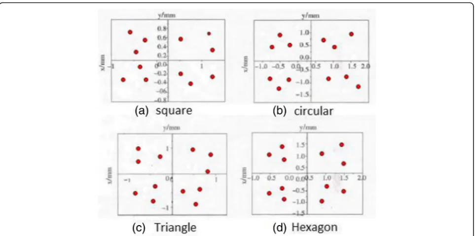
According to the four models of the regular quadrilat-eral, circular, regular triangle, and regular hexagon, from 0°, each rotation 45° operation of visual robot grasping model, each model is grabbed 10 times, and the distribu-tion of grabbing center point is as shown in Fig. 6. The visual robot localizes the different shapes according to the grasping center points shown in Fig.6 and gets the positioning grasping error as shown in Fig.7.
Figure7shows the robot arm positioning error at dif-ferent model placement angles. According to the visual robot’s positioning error for different angles of different models, this paper calculates the positioning error of visual robots for different models. The average posi-tioning error of the regular quadrilateral is 0.86 mm, the average positioning error of the circular shape is 0.8 mm, and the average positioning errors for the tri-angle and the hexagon are 0.93 mm and 1.27 mm, re-spectively. The data results show that the robot system will produce different positioning errors for different
Fig. 4Feature extraction of images using different algorithms
shape models. The mean value of the positioning error of the visual robot for the regular quadrilateral and the circle is significantly smaller than the mean value of the positioning error for the triangle and the hexagon. Therefore, the use of a regular quadrilateral and circu-lar model with low positioning error rate can improve the accuracy of positioning.
In addition, in order to compare the positioning time of the visual robot to different shape models, this paper uses the visual robot to perform 10 times of positioning on different shape models. Then, the positioning calcula-tion time of the visual robot for 10 times of each model is compared. The positioning calculation time of each model is shown in Fig.8.
Fig. 6Regular quadrilateral, circular, regular triangle, and regular hexagon grab central points respectively
It can be seen from Fig.8 that among the four differ-ent shape models, the 10 positioning times of the square and circular models are generally relatively small. In this paper, the time average of the positioning calculation of each model is calculated according to the data of Fig.8. The result shows that the average positioning time of the square is 8850 ms, the average positioning time of the circle is 8860 ms, the average positioning time of the triangle is 9700 ms, and the positioning time of the regular hexagon is 9630 ms. The positioning time of po-sitioning square and circular is smaller. Therefore, when the same size is available, the real time of locating squares and circles is greater than that of triangles and hexagons.
4.2 Positioning of visual robots for models of the same shape and different sizes
The purpose of this experiment is to find out the posi-tioning of the visual robot for models of the same shape and different sizes. Therefore, this experiment uses the camera of the mobile robot to take four different shapes of photos, each of which has an image size of 800 × 600 pixels. In turn, 10 subgraphs of four different shape
models are obtained by decreasing by 10% in turn. The
square model shown in Fig. 9 shows a group diagram
from 100 to 10%.
The system uses the SURF algorithm to extract fea-tures from 10 subgraphs of each shape model. The result is shown in Fig.10. Figure10is a graph showing the re-lationship between the number of feature points of the 10 sub-pictures of different shape models and the size of the image. As can be seen from Fig. 10, the number of feature points of four differently shaped images gradually increases as the image size increases. When the size ra-tio of each shape image changes between 10 and 40%, the change of the feature points is relatively large, and the variation range of the feature points of all shapes is basically about 35 points. When the image size ratio changes between 40 and 100%, the change of the feature points is relatively stable, and the curve is relatively smooth. The range of the feature points of all shapes is basically within 15 points.
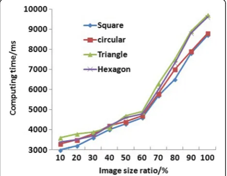
Then, this paper compares the positioning calculation time and image size of different shape models. The re-sult is shown in Fig.11. Figure11is a graph showing the relationship between the positioning calculation time
Fig. 8Comparison of 10 positioning calculation times for different shape models
and the image size of images of different shapes. It can be seen from Fig.11that the image positioning calcula-tion time of four different shapes also increases with the increase of the image size. When the image size ratio changes between 10 and 60%, the time curve of the posi-tioning calculation is relatively smooth, and the variation interval is 3000–5000 ms. When the image size ratio changes between 60 and 100%, the location calculation time changes faster and the variation interval is 5000– 10000 ms.
Therefore, considering the change of the integrated positioning calculation time and the number of feature points, when the image size ratio is between 40 and 60% of the original image, the change of the feature points is relatively stable, and the number of feature points is moderate, which can ensure a certain positioning
accuracy. And when the image size ratio changes be-tween 40 and 60% of the original image, the change in the positioning calculation time is also relatively gentle. Therefore, when the image size ratio changes between 40 and 60% of the original image, the real-time visibility of the mobile robot can be improved under the premise of ensuring a certain positioning accuracy.
5 Conclusions
When the indoor mobile robot is autonomously posi-tioned, the visual positioning system has high require-ments on the real-time performance of visual positioning, but the accuracy of image recognition is not high. To this end, researchers have started to improve the real-time per-formance of visual robot systems in many aspects. Some researchers have found that the image shape and image size to be positioned have a great influence on the posi-tioning calculation time. In order to verify this conclusion and find the appropriate image shape and size to meet the requirements of robot vision positioning, this paper uses four different shapes of quadrilateral, circular, equilateral, and regular hexagons and uses SURF algorithm to study the influence of image shape and image size on the real-time positioning of the visual robot from the position-ing of various shape models under the same size and the positioning of the visual robot to the same shape and dif-ferent size models. It is found that (1) in the case of four different shapes in the same size, the accuracy and real time of the square and circular location of the visual posi-tioning system is higher than that of the triangles and hexagons. (2) For four different shapes, when the size ratio of the original image varies between 40 and 60% of the original image, it can improve the real-time visual localization of the mobile robot on the premise of ensur-ing a certain location accuracy.
Abbreviations
CCD:Charge-coupled device; DoG: Difference of Gaussian; SIFT: Scale invariant features transform; SURF: Speeded-Up Robust Features
Acknowledgements
The authors thank the editor and anonymous reviewers for their helpful comments and valuable suggestions.
Funding
This work was supported by the MOC (Ministry of Culture in China) Funded Project for Key Laboratory in 2017 and National Natural Science Foundation of China (no. 61375081).
Availability of data and materials We can provide the data.
About the authors
Desheng Lyu was born in Harbin, Heilongjiang, People’s Republic of China, in 1976. He received his doctor’s degree from Harbin Institute of Technology, People’s Republic of China. Now, he works in Key Laboratory of Interactive Media Design and Equipment Service Innovation (Ministry of Culture), Harbin Institute of Technology. His research interests include digital media, virtual reality, and intelligent robotics.
Fig. 10Relationship between feature points and image size of images of different shapes
Heyang Xia was born in Harbin, Heilongjiang, People’s Republic of China, in 1994. He received the bachelor’s degree from Harbin Institute of Technology, People’s Republic of China. Now, he studies his master’s degree at Department of Media Technology and Art, Harbin Institute of Technology. His research interests include game development, virtual reality, and intelligent robotics.
Chen Wang was born in Harbin, Heilongjiang, People’s Republic of China, in 1979. He received his master’s degree from Harbin Institute of Technology, People’s Republic of China. Now, he works in Key Laboratory of Interactive Media Design and Equipment Service Innovation (Ministry of Culture), Harbin Institute of Technology. His research interests include digital arts, virtual reality, and interactive design.
Authors’contributions
All authors take part in the discussion of the work described in this paper. The author DL wrote the first version of the paper. The author HX did a part of the experiments of the paper, and CW revised the paper in different version of the paper. All authors read and approved the final version of the manuscript.
Ethics approval and consent to participate Approved.
Consent for publication Approved.
Competing interests
The author declares that they have no competing interests.
Publisher’s Note
Springer Nature remains neutral with regard to jurisdictional claims in published maps and institutional affiliations.
Received: 5 June 2018 Accepted: 30 August 2018
References
1. De Xu, Robot Vision Measurement and Control[M]. Second Edition. Beijing: National Defense Industry Press,2011
2. C. Schmid, R. Mohr, Local grayvalue invariants for image retrieval[J]. IEEE Trans. Pattern Anal. Mach. Intell19(5), 530–535 (1997)
3. K. Mikolajczyk, C. Schmid, Indexing based on scale invariant interest points[J]. Proc.Int.Conf.Comput.Vis. Vancouver Canada, 1 (2010)
4. K. Mikolajczyk, C. Schmid, Scale & affine invariant interest point detectors[J]. Int. J. Comput. Vis60(1), 63–86 (2004)
5. Lowe D G. Object Recognition from Local Scale-Invariant Features[C]. In: Proceedings of the Seventh IEEE International Conference on Computer Vision (IEEE, 1999), pp. 1150–1176
6. Mikolajczyk K, Schmid C. A performance evaluation of local descriptors[C]. IEEE Trans.27(10), 257 (2013)
7. H. Bay, A. Ess, T. Tuytelaars, et al., Speeded-up robust features[J]. Comput. Vis. Image Underst110(3), 404–417 (2008)
8. X.J. Liu, J. Yang, J.W. Sun, et al., Image registration approach based on SIFT[J]. Infrared Laser Eng37(1), 156–160 (2008)
9. L. Jia, W. Fu, W. Wen, et al., Image matching based on improved SIFT algorithm[J]. Chin. J. Sci. Instrum34(5), 1107–1112 (2013)
10. Li B, Liu L, Wei Z Q. A strong robust real-time image matching algorithm[J]. Journal of Software. (7), 1583–1592 (2014)
11. Wang G, Yu J, Hou Y. An image registration algorithm based on features point and cluster[C]. International Congress on Image and Signal Processing IEEE. 836–840 2013
12. C.J. Harris, A combined corner and edge detector[J]. Proc. Alvey Vis. Conf
1988(3), 147–151 (1988)
13. C. Jian, L.I. Kan, C.X. Gao, et al., Application of local features in aerial image mosaic[J]. J. Univ. Electron. Sci. Technol. China42(1), 125–129 (2013) 14. Ke Y, Sukthankar R. PCA-SIFT: a more distinctive representation for local
image descriptors[C]// Computer Vision and Pattern Recognition, 2004. CVPR 2004. Proceedings of the 2004 IEEE Computer Society Conference on. IEEE. 506–513 (2004)
15. Han L I, Niu J Z, Guo H. Automatic seamless image mosaic method based on feature points[J]. Computer Engineering & Design28(9), 2083–2085 (2007)
16. M. Pateraki, H. Baltzakis, P. Trahanias, Visual estimation of pointed targets for robot guidance via fusion of face pose and hand orientation☆[J]. Comput. Vis. Image. Underst120(5), 1–13 (2013)
17. P.F. Alcantarilla, L.M. Bergasa, et al., Gauge-SURF descriptors[J]. Image. Vis. Comput31(1), 103–116 (2013)
18. F. Bellavia, D. Tegolo, C. Valenti, Keypoint descriptor matching with context-based orientation estimation☆[J]. Image. Vis. Comput32(9), 559–567 (2014) 19. H. Mehrotra, P.K. Sa, B. Majhi, Fast segmentation and adaptive SURF descriptor
for iris recognition[J]. Math. Comput. Model58(1–2, 132),–146 (2013) 20. D.G. Lowe, Distinctive image features from scale-invariant keypoints[J]. Int. J.
Comput. Vis.60(2), 91–110 (2004)