R E S E A R C H
Open Access
Mobile robot location algorithm based on
image processing technology
Guifeng Wu
*, Jie Zheng, Jiatong Bao and Shengquan Li
Abstract
To improve the reconfigurable micro mobile robot cluster system based on precision detection, a positioning and tracking system based on computer digital image processing technology was developed. The system consisted of three subsystems: image acquisition and preprocessing subsystem, rapid positioning subsystem based on robot marker recognition, and tracking subsystem based on position estimation. First, after studying the related algorithms in the subsystem, the threshold selection method of adaptive gray weight conversion was proposed for image preprocessing. Then, a fast positioning method based on marker recognition for miniature mobile robots was proposed. The selection of micro-robot markers and the basis for judging the selection of moments were given. A triangular projection positioning method was implemented, and related experimental results were given. Finally, the windowing scanning algorithm was optimized. According to the speed and direction of the robot, a tracking algorithm for position estimation was proposed. Through the simulation experiment, the effect of system positioning tracking and the system reference time in 0.270 s were given. The results showed that the system had high real-time performance.
Keywords: Mobile robot, Positioning and tracking, Image processing technology
1 Introduction
MEMS are microelectronic mechanical systems. It is a very important technology for micro/nanotechnology [1]. After more than 10 years of development, the demand for micro-electromechanical systems that integrates micro-sen-sors, microprocesmicro-sen-sors, and micro-actuators has been in-creasing [2]. The development of multi-functional MEMS products has become a hot topic. Miniature mobile robots are new robotics technologies based on MEMS technology. The miniature mobile robot is small in size. Its adaptability is strong. It has unique advantages in the detection and pre-cise detection of complex and unknown environments [3].
The micro mobile robot is a new robot technology devel-oped based on MEMS technology. Compared with conven-tional robots, micro mobile robots can be used effectively in unknown and complex environments [4]. For example, rescue operations in complex and dangerous environments
are difficult for ordinary robots to perform operations in an unknown environment. However, a miniature mobile robot can adapt to various terrains with its strong adapt-ability and it can detect unknown environments and carry out rescue work through small caliber pipes. Therefore, the research of micro-robots has received extensive attention, and its superiority has also been recognized [5].
To realize the micro mobile robot reconstruction tech-nology, the miniature mobile robot must be precisely con-trolled. However, for precise control, accurate positioning of the mobile micro-robot and its path tracking are par-ticularly important. If the location tracking system is not equipped, the controller does not know the actual situ-ation of the miniature mobile robot in a complex environ-ment. It not only greatly restricts the development of micro-robot technology but also sets obstacles for realiz-ing the reconstruction of micro-mobile robots. Based on the above reasons, a set of precise positioning of multiple micro mobile robots is proposed. It provides precise con-trol of micro-robots through a real-time tracking system. Therefore, accurate positioning and tracking of the micro mobile robot is achieved. This lays a solid foundation for the reconstruction technology of micro mobile robots [6]. * Correspondence:[email protected]
Department of Electrical Engineering, Yangzhou University, 196 Huayang West Road, Yangzhou 225127, Jiangsu, China
2 State of the art
The difference between a modular robot and a conven-tional robot is that it can be used very effectively in unknown environments and complex environments. Proteo is an unconventional reconfigurable module robot. It was proposed by Japanese scholars in 2000. Each module of the robot is a rhombic dodecahedron. Each surface has a cer-tain connection mechanism, so that modules and modules can be interconnected. The bindiny mechanism is mainly composed of electromagnets. The electromagnet bindiny mechanism is mainly distributed on the edge of each surface. The robot system is made up of a series of diamond homogeneous units.
The Fractal reconfigurable robot was proposed by the German scholar Michale in 1994. Fractal is a robot con-sisting of a series of identical cubes and bolts and a series of slots. Each surface of the cube has bolts and grooves. Through these mechanisms of bolts and grooves, the robot completes geometric transformations to accomplish specific tasks. The structure of the robot is achieved by sliding a cube or series of cubes on the contact surface. This mechanism seems to be difficult to achieve in reality. Research results show that the vast majority of it only appears in simulations.
Robot positioning is an indispensable part of the reconfigurability of micro-mobile robots. Meng et al. used eight Polaroid sonars to extract features such as planes, corners, and cylinders in an indoor environment and used AEKF fusion encoders and sonar information to locate robots. Drumheller extracts line segment fea-tures from the indoor environment information acquired by the sonar and matches the map to locate the robot. However, the accuracy of sonar measurement is not high. It has a“blind”defect. There is a great deal of un-certainty in the data returned by sonar.
3 Method: the processing flow of the global positioning and tracking system
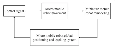
The micro mobile robot global positioning tracking sys-tem is used to locate the multiple robot clusters on the experimental platform and capture the tracking system in real time according to their trajectories. It is in the entire micro-mobile robot experimental platform in the information acquisition, and the real-time position infor-mation is passed to the control system. The control sys-tem corrects the moving route of the mobile robot so as to realize the overall control of the miniature mobile robot cluster and achieve the purpose of reconstruction. Therefore, in the entire micro mobile robot experimen-tal platform system, it is in the status of information recovery and feedback loop, as shown in Fig.1.
According to the characteristics of the mobile robot platform, the global positioning system of the micro mo-bile robot consists of three major subsystems. The three
major subsystems are the image acquisition and image preprocessing module, the micro mobile robot label iden-tification and positioning module, and the micro mobile robot position estimation and tracking module.
4 Preprocessing of scene images of miniature mobile robots
The image processing method mainly performs preprocess-ing, filterpreprocess-ing, and segmentation on the image. This lays the foundation for subsequent location tracking. The complex-ity of subsequent operations is reduced, the accuracy is improved, and the real-time effects of the overall system are improved.
The Gaussian kernel smoothing filter is an excellent smoothing filter with very good performance. If the spatial domain error is Δx, the frequency domain error isΔω. Their relationship is as in formula (1):
ΔxΔω≥1
4 ð1Þ
The choice of the best filter is to optimize this rela-tionship. The Fourier transform of the Gaussian function is still a Gaussian function. Therefore, the Gaussian function can form a low-pass filter with smooth per-formance in both the time domain and the frequency domain. Gaussian filters can be optimized in both the time and frequency domains [7].
A Gaussian smoothing filter is used to filter the scene image. The template operation is used in the specific processing process, which can avoid complicated math-ematical calculations, and the method is simple and the processing speed is fast. The Gaussian template used is:
1 16
1 2 1 2 4 2 1 2 1
2 4
3
5 ð2Þ
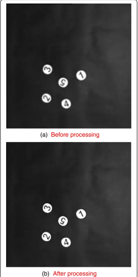
The processing results are shown in Fig.2.
Image segmentation is based on the criteria of image features or feature sets to divide the image plane into a series of “meaningful” regions, which is the first thing that needs to be done to achieve automatic image analysis. In the Figs.1,2,3,4, and5represents the part that needs to
Control signal Micro mobile robot movement
Miniature mobile robot remodeling
Micro mobile robot global positioning and tracking system
be smoothed.Taking the system processing reference time as the standard, the grayscale threshold segmentation is used to binarize the image. The theory of classical grayscale adap-tive threshold selection was introduced. Combined with the particularity of the experimental scene, a method of scene binarization based on adaptive gray threshold selection is proposed. This method has a fast processing speed, good real-time performance, and good segmentation effect.
A simpler method of adaptive threshold selection is to determine a neighborhood window centered on each pixel, calculate the maximum and minimum values of
the pixels in the window, and then take their mean as the threshold [8]. C represents the current pixel, and P is an eight-neighbor pixel of C. maxValue represents the maximum gray value of the eight-neighborhood pixels, and minValue represents the minimum gray value of the eight-neighborhood pixels. The threshold is set to:
T ¼maxValueþminValue
2 ð3Þ
The 50*50-pixel window is used for the alignment scan. In this way, the adaptive threshold selection can be completed with the highest efficiency and the image seg-mentation binarization processing can be completed.
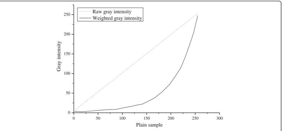
Grayscale histogram extraction is performed on the image in the scanning window, and different grayscale in-tensities are weighted. The grayscale threshold of the image area is between 250 and 255. Therefore, the weight of the grayscale intensity in the threshold of the region is increased, and the weight of the grayscale intensity of the image background is correspondingly reduced.
Figure3 shows the experimental results of gray weight conversion. Two hundred fifty different pixels were used. The gradations are 0 to 250, respectively. After completing the weighted histogram extraction, the optimal gray threshold is selected by means of the concept of low-pass filter in the discrete signal processing system [9]:
Tbest ¼ max Ti1nImax
1nITi
β;Ti<TImax
ð4Þ
In Eq. (4),Tbest represents the optimal gray threshold.
Imax represents the strongest grayscale intensity in the
window. TImax represents the grayscale threshold of the
grayscale corresponding to the strongest grayscale inten-sity. βis a fixed constant. The optimal gray threshold is to find the first gray point with the attenuation degreeβ from the strongest point of gray to the minimum gray direction and use this point as the optimal gray thresh-old. In the system, the value ofβis 2.3.
Under the same conditions, this kind of image binari-zation method based on adaptive selection of optimal gray-scale threshold was simulated. Since the method first looks for Tbest, when theTbest does not exist, it is
no longer necessary to perform calculations on the pixels within the window. As a result, the computational overhead is significantly reduced. The reference time is only 23 ms. This method is still applicable in the envir-onment where the continuity of light changes. There-fore, this method was chosen to be used in the global positioning and tracking system of miniature mobile ro-bots. Figure4shows the result of image segmentation. (a) Before processing
(b) After processing
5 Fast localization of micro mobile robot based on mark recognition
5.1 Feature extraction and marker selection of robot markers
The feature description of the robot tag refers to the use of some special algorithms to extract the imaged robot tag information. Its unique features are preserved. It can be described in computer-cognizable form, such as numerical value and display, so as to realize the description of the mark. This form of computer-recognized image informa-tion is called the feature value of the image [10]. The char-acteristic value of the image may be a single value, but it may also be a set of single values. Regardless of the image
feature value has several numeric elements, it must have a one-to-one correspondence with the image tag itself.
The moment invariant of the image is used to mark the robot. The geometric moment function is defined as follows:
mpq¼
X
x;y
ð Þ∈C
xpyqf xð ;yÞ ð5Þ
μpq¼
X
x;y
ð Þ∈C x−x
ð Þpðy−yÞqf xð ;yÞ ð6Þ
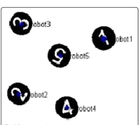
Five different micro mobile robots need to be tracked in the micro mobile robot global positioning tracking
0 50 100 150 200 250 300
0 50 100 150 200 250
Gray intensity
Plain sample Raw gray intensity
Weighted gray intensity
Fig. 3The gray-weight transfer experiment
(a)
Original scene(b)
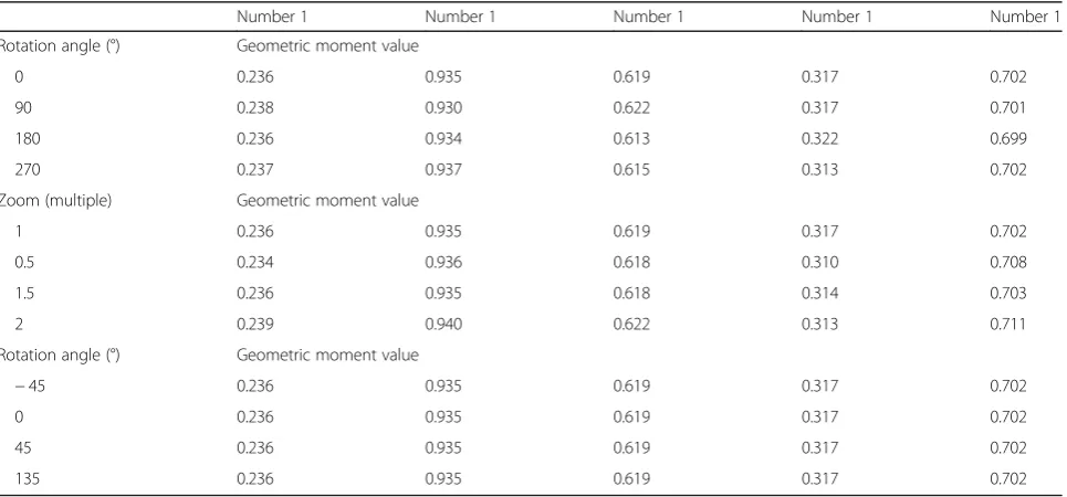
The result of the binarization of the imagesystem. According to the requirements, the five micro mo-bile robot models are marked with Arabic numerals, and the circular geometric shape embedded with Arabic nu-merals is used as the robot candidate mark.nis 3, andmis 1. The geometric moments were tested under the same conditions. The experimental results are shown in Table1:
It can be seen from the experimental results that the geometric moment value is outstanding in the rotation and translation, which meets the system requirements. There is a slight deviation in the dimensional invariance, but the system does not require high-dimensional invari-ance. Therefore, the geometric moment image feature op-erator satisfies the needs of the system, and the algorithm is used to match the robot markers on the scene image.
When the tag recognition system completes the identifi-cation of the image scene robot, and locks the area, it is necessary to calculate the center point of the marker, so as to determine the location of the robot. The common prac-tice is to scan the entire area of the black pixel in the area and calculate the center position of the black pixel. Then, the white pixel center position is calculated in the same way. The weighted average of two center positions and the marked center position is considered to be the position of the robot’s scene.
This general positioning method is very accurate for strictly geometrically symmetrical graphics. However, the system’s tags include Arabic numerals. It is non-geometric-ally symmetrical. Therefore, the traditional positioning method will affect the positioning accuracy. A triangular projection mapping method based on the principle of simi-lar triangles is proposed. The principle is shown in Fig. 5. The principle is a similar triangular projection mapping. The algorithm is also named accordingly.
The circular mark is reduced to the base of the triangle, and the diameter D of the circular mark is the base of the triangle. For a given base, an isosceles tri-angle with a height of H can always be made. Obviously, the apex O of the isosceles triangle at this time is the projection of the circular mark center C in the isosceles triangle region. The remaining points can also be con-verged to the apex through an isosceles triangle projec-tion. According to the triangular projection mapping method, only the black pixel point information of the edge of the mark is needed to calculate the position of the center point, so that the center position of the mark is accurately calculated. The positioning of the miniature mobile robot in the global scene is realized.
5.2 Implementation of robot marking recognition and positioning subsystem
Figure6shows the flow chart of the marking and location subsystem of micro mobile robot. When the subsystem receives the preprocessed robot scene image sent by the image preprocessing subsystem, a 50*50 window scanning is performed and the black and white ratio calculation is performed. When the black-and-white pixel ratio of the image scene information in the scanning window is close to the mark black and white ratio, the window is locked and the moment value is judged, and the robot serial number is obtained.
Then, a triangular projection mapping is performed to obtain the position of the mark in the image scene. Since the actual scene of the robot corresponds to the image scene one by one, when the position marked in the image scene is obtained, the position of the robot in the actual scene is also determined. Figure 7 shows the
Table 1Verification of geometric moments
Number 1 Number 1 Number 1 Number 1 Number 1
Rotation angle (°) Geometric moment value
0 0.236 0.935 0.619 0.317 0.702
90 0.238 0.930 0.622 0.317 0.701
180 0.236 0.934 0.613 0.322 0.699
270 0.237 0.937 0.615 0.313 0.702
Zoom (multiple) Geometric moment value
1 0.236 0.935 0.619 0.317 0.702
0.5 0.234 0.936 0.618 0.310 0.708
1.5 0.236 0.935 0.618 0.314 0.703
2 0.239 0.940 0.622 0.313 0.711
Rotation angle (°) Geometric moment value
−45 0.236 0.935 0.619 0.317 0.702
0 0.236 0.935 0.619 0.317 0.702
45 0.236 0.935 0.619 0.317 0.702
experimental results. The blue dot indicates the center of the mark, that is, the position of the robot. The entire process takes about 220 ms of reference time.
6 Fast localization results and discussions of micro mobile robot based on mark recognition Robot tracking is the same as robot identification and positioning. It is also a hot issue in recent years. The en-tire micro mobile robot global positioning tracking sys-tem is based on image processing technology. The trajectory of the robot movement also changes in real time with the interference factors of the control system, such as noise and mechanical factors, and the given path is not determined. The robot itself has very low random mobility. Therefore, the image window scanning method tracks the positioned micro mobile robot.
6.1 Traditional scans and tracking
The traditional fenestration scan tracking algorithm is relatively simple, but its limitations are very large. Trad-itional window scanning and tracking algorithms have high requirements on the real-time performance of the system. If the system’s real-time performance is not enough or the robot moves too fast, it will cause the robot to run out of the established window scanning range, resulting in the failure of the tracking algorithm. To solve this problem, the window scanning window can only be expanded. However, the risk of expanding
r
D
Fig. 5Triangle projection mapping
Scene image
Image scene marker scan
Mark pixel ratio comparison
Marker moment value comparison
The tag is locked with the robot
Triangular projection positioning
Save the information
Fig. 6Flow chart of the identification and positioning subsystem for micro mobile robots
the window scanning window is to further reduce the real-time performance of the system. Since the number of scanned pixels is squared-increase, the time complex-ity of the algorithm increases with the increase of the windowing window into a geometric progression, which will greatly reduce the real-time performance of the sys-tem. It can be seen from the above that the traditional method of window selection for window scanning and tracking has certain blindness. Therefore, traditional window tracking algorithms cannot be applied to global positioning and tracking systems.
6.2 Velocity-based location prediction and tracking algorithm for mobile robots
Considering the limitations of traditional fenestration and tracking, the algorithm is improved according to the actual situation of the micro mobile robot system. Com-bined with the traditional method of window scanning, a position prediction system based on robot speed is pro-posed, which can achieve a targeted window scan tracking, thus solving the influence of the limitation of the window scans and tracking method. The speed-based position esti-mation tracking algorithm first implements the speed con-version, that is, the actual speed value (mm/s) is converted into a value (pixs/s) that passes the pixel points per second. This value is called the image scene speed value. The position estimation of a speed-based miniature mobile robot can be represented as shown in Fig.8.
The initial position is O(x,y) and the estimated position is O′(x,y).His:
H:O0
¼Oþu•T ð5Þ
O′(x,y) is obtained. When the scene of the next frame of the image is obtained, a square is scanned with O(x,y) as the center andρaas the side.ais the length of the external square of the robot marker, andρis the suppression error coefficient. There is noise in the control system. The micro-robot experimental platform inevitably causes mech-anical errors. It will further cause the deviation of the
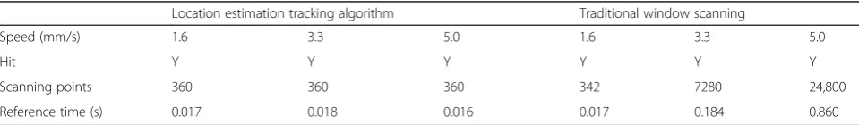
robot’s motion path. Theρvalue is 1.2 in this system. The position estimation tracking algorithm and the traditional windowing scanning algorithm are compared through simulation experiments. The experimental results are shown in Table2.
Obviously, the position estimation tracking algorithm greatly reduces the number of points for window scan-ning, increases the real-time performance of the system, and achieves the purpose of rapid capture and tracking.
6.3 Implementation of tracking algorithm based on position prediction
The position estimation tracking algorithm is simulated on the MATLAB simulation platform. The flow chart is shown as in Fig.9. When the global positioning control system gets the global mobile robot global image scene for the first time and passes through the image prepro-cessing subsystem and the mark recognition subsystem, the position of the next position of the micro mobile robot is estimated. When the system receives the image processed by the image preprocessing subsystem for the second time, window scanning is performed on the image scene at the estimated position. The positioning of the robot was then performed using a triangular pro-jection method. The reference time for the entire global positioning and tracking system is 0.270 s.
7 Conclusions
A global positioning and tracking system based on mini-ature mobile robots was discussed. The system mainly includes three major subsystems: image acquisition and preprocessing subsystems, robot tag identification and positioning subsystems, and position estimation-based tracking subsystems.
In the image acquisition and preprocessing subsystem, the method of gray adaptive selection suitable for the system is proposed, and the experimental results are given. Based on the marker recognition, a robot-based marker image recognition method is proposed to locate the robot. The shape of the micro-robot mark is se-lected, and the image moment that describes the mark feature is most suitable. The triangular projection map-ping positioning method for fast positioning is described. Finally, the specific implementation of the subsystem is given, as well as the reference time and scene effects. In the location estimation and tracking research, a window
O (x,y) H (x)
H (y) O (x,y)
Fig. 8Position estimation block diagram
Table 2Experimental comparison of position prediction tracking algorithm
Location estimation tracking algorithm Traditional window scanning
Speed (mm/s) 1.6 3.3 5.0 1.6 3.3 5.0
Hit Y Y Y Y Y Y
Scanning points 360 360 360 342 7280 24,800
estimation scanning algorithm based on position estimation is proposed. Based on the comparison of experimental re-sults, the correction of the traditional window-opening scanning tracking algorithm based on the position estimation-based window scanning tracking algorithm is given. The specific process and simulation results of the subsystem implementation are given.
A global positioning tracking system for miniature mobile robots was studied. At present, the system reference period is 0.277 s. Real-time performance basically meets the re-quirements. However, if the system reference time can be further shortened and the real-time performance is further improved, the positioning accuracy of the system will also be improved. This system is based on the reconstruction of micro-robots. The positioning and tracking of the micro mobile robot is realized, but it does not have the function of detecting the direction of motion of the robot. Since the reconstruction of the micro mobile robot requires the docking of the connector, there is also a requirement for direction detection with the robot. To serve the micro-robot reconstruction, the global positioning and tracking system should also add the function of detecting the direction of the micro-mobile robot, which is conveni-ent for the reconstruction of the micro-mobile cluster. In addition, the global positioning and tracking system should also have the monitoring function of the overall coordi-nated control of the robot cluster. The system should be added to the overall coordinated control and monitoring of the robot cluster to realize the role of the robot barrier and the overall motion path planning, so as to prepare for the real reconstruction of the micro mobile robot.
Acknowledgements
The authors thank the editor and anonymous reviewers for their helpful comments and valuable suggestions.
About the Authors
Guifeng Wu, Master of Engineering, Associate Professor, graduated from the Southeast University in 2004 and worked in Yangzhou University. His research interests include modern measurement and control technology, human-computer system, and blended teaching.
Jie Zheng, Master of Engineering, Associate Professor, graduated from the Southeast University in 1999 and worked in Yangzhou University. Her research interests include communication and electronic technology. Jiatong Bao, Doctor of Technical Science, Lecturer, graduated from the Southeast University in 2013 and worked in Yangzhou University. His research interests include human-computer interaction technology, robot sensing, and control.
Shengquan Li, Doctor of Technical Science, Associate Professor, Graduated from the School of Aerospace Engineering, Nanjing University of Aeronautics and Astronautics in 2012, worked in Yangzhou University. His research interests include disturbance estimation and compensation and its application to mechatronics systems.
Funding
1. National Natural Science Foundation of China (61773335) 2. Natural Science Foundation of Jiangsu Province (BK20150454) 3. Excellent teaching team of Yangzhou University (ETT20171066)
Availability of data and materials
Authors can provide the data.
Author’s contributions
All authors take part in the discussion of the work described in this paper. The author GW wrote the first version of the paper. The author JZ and JB did part experiments of the paper. SL revised the paper in different version of the paper, respectively. All authors read and approved the final manuscript.
Competing interests
The authors declare that they have no competing interests.
Publisher’s Note
Springer Nature remains neutral with regard to jurisdictional claims in published maps and institutional affiliations.
Received: 4 June 2018 Accepted: 2 October 2018
References
1. S. Park, K.S. Roh, Coarse-to-fine localization for a mobile robot based on place learning with a 2-D range scan. IEEE Trans. Robot.32(3), 528–544 (2016) 2. J. Simanek, V. Kubelka, M. Reinstein, Improving multi-modal data fusion by
anomaly detection. Auton. Robot.39(2), 139–154 (2015)
3. P. Yang, W. Wu, Efficient particle filter localization algorithm in dense passive RFID tag environment. IEEE Trans. Ind. Electron.61(10), 5641–5651 (2014) 4. B. Benjamin, G. Erinc, S. Carpin, Real-time WiFi localization of heterogeneous
robot teams using an online random forest. Auton. Robot.39(2), 155–167 (2015) 5. J. Kim, W. Chung, Localization of a mobile robot using a laser range finder in a glass-walled environment. IEEE Trans. Ind. Electron.63(6), 3616–3627 (2016) 6. S. Safavi, U.A. Khan, An opportunistic linear–convex algorithm for localization in
mobile robot networks. IEEE Transactions on Robotics PP99, 1–14 (2017) 7. S. Halder, A. Ghosal, A survey on mobile anchor assisted localization
techniques in wireless sensor networks. Wirel. Netw22(7), 1–20 (2016) 8. G. Feng, Y. He, J. Han, Active persistent localization of a three-dimensional
moving target under set-membership uncertainty description through cooperation of multiple mobile robots. IEEE Trans. Ind. Electron.62(8), 4958– 4971 (2015)
9. H.Y. Chung, C.C. Hou, Y.S. Chen, Indoor intelligent mobile robot localization using fuzzy compensation and Kalman filter to fuse the data of gyroscope and magnetometer. IEEE Trans. Ind. Electron.62(10), 6436–6447 (2015) 10. I. Becerra et al., Reliable confirmation of an object identity by a mobile robot: a mixed appearance/localization-driven motion approach. Int. J. Robot. Res.10, 35 (2016)
Get the first image scene
The velocity of the previous cycle is estimated
Image scene estimation position open window scan
Triangular projection legal position
Speed position estimation
Save the information Image preprocessing
system image scene
N
Y