259 | P a g e
AN OVERVIEW OF DYNAMIC VOLTAGE RESTORER
FOR VOLTAGE SAG AND SWELL COMPENSATION
Vishal Wadkar
1, Deepak Sonje
21
PG Student,
2Assistant Professor, Department of Electrical Engineering,
R.H. Sapat College of Engineering, Nashik, (India)
ABSTRACT
Dynamic Voltage Restorer (DVR) is a custom power device that is used to improve voltage disturbances in
electrical distribution system. The components of the DVR consist of voltage source inverter (VSI), injection
transformers, passive filters and energy storage. The main function of the DVR is used to inject three phase
voltage in series and in synchronism with the grid voltages in order to compensate voltage disturbances. The
Development of (DVR) has been proposed by many researchers. This paper presents a review of the researches
on the DVR application for power quality Improvement in electrical distribution network. The types of DVR
control strategies and its configuration has been discussed and may assist the researchers in this area to
develop and proposed their new idea in order to build the prototype and controller.
Keywords: Dynamic Voltage Restorer, Voltage Source Inverter, Power Quality.
I.
INTRODUCTION
Recently applications of power electronic controller based on Custom Power Devices (CPD) are widely used in electrical distribution system for power quality improvement. CPD is a powerful tool based on semiconductor switches concept to protect sensitive loads if there is a disturbance from power line. Among the several novel CPD, the Dynamic Voltage Restorer (DVR) are now becoming more established in industry to mitigate
260 | P a g e
II. DYNAMIC VOLTAGE RESTORER
The conventional circuit configuration of the DVR is shown in Figure 2. Dynamic voltage restorer is a series connected device is used for mitigating voltage disturbances in the distribution system. DVR maintains the load voltage at a nominal magnitude and phase by compensating the voltage sag/swell, voltage unbalance and voltage harmonics presented at the point of common coupling. These systems are able to compensate voltage sags by increasing the appropriate voltages in series with the supply voltage, and therefore avoid a loss of power. The DVR should capable to react as fast as possible to inject the missing voltage to the system due to sensitive loads are very sensitive to voltage variations. The DVR is a series conditioner based on a pulse width modulated voltage source inverter, which is generating or absorbing real or reactive power independently.
Fig. 2 Conventional Circuit Configuration of DVR
III. COMPONENTS OF DVR
The DVR system consists of two important sections namely a power circuit and a control unit. Power circuit of DVR basically consists of a voltage source inverter, a series connected injection transformer, passive filter, and an energy storage device that is connected to the dc link. In DVR the control circuit is used to derive the parameters (magnitude, frequency, phase shift, etc) of the control signal that has to be injected by the DVR. Based on the control signal, the injected voltage is generated by the switches in the power circuit.
3.1 Series Voltage Injection Transformers:
261 | P a g e
maximum compensation ability of the DVR. The three single phase transformers connection used in the three-phase DVR can be configured either in delta/open or star/open connection.
3.2 Energy Storage:
The DVR needs real power for compensation purposes during voltage disturbances in the distribution system. In this case the real power of the DVR must be supplied by energy storage when the voltage disturbances exist. The energy storage such as a battery is responsible to supply an energy source in DC form. Energy storage consists of two types form. One using stored energy to supply the delivered power and the other having no significant internal energy storage but instead energy is taken from the faulted grid supply during the sags. A shunt–converter or the rectifier is the main sources of the direct energy storage which is supplied to DVR. Flywheels, batteries, superconducting magnetic energy storage (SMES) and super capacitors can be used as energy storage devices. It supplies the real power requirements of the system when DVR is used for compensation. The application of the energy storage in DVR is depending on the designed rating required and total cost is also must be considered. Lead acid batteries are popular among the others owing to its high response during charging and discharging. But the discharge rate is dependent on the chemical reaction rate of the battery so that the available energy inside the battery is determined by its discharge rate. Storage systems with auxiliary supply is used to increase the system performance when the grid of DVR is weak. The suitable of the type of energy storage depend on the DVR designed in term rated power and the total cost factor.
3.3 LC Filter:
Basically filter unit consists of inductor (L) and capacitor (C). In DVR, filters are used to convert the inverted PWM waveform into a sinusoidal waveform. This can be achieved by eliminating the unwanted harmonic components generated by the VSI action. Higher orders harmonic components distort the compensated output voltage. The unnecessary switching harmonics generated by the VSI must be removed from the injected voltage waveform in order to maintain an acceptable Total Harmonics Distortion (THD) level. The switching frequencies of the VSI are usually up to several kHz for medium power level. The passive filters can be placed either in the high voltage or in low voltage side winding of the series injection transformer. If the filter is installed at the low voltage side it has the advantage of being closer to the harmonic source thus high order harmonic currents are avoided to penetrate into the series injection transformer. Harmonics currents will circulate into the series injection transformer if the filtering scheme is placed at the high voltage.
3.4 Voltage Source Inverter (VSI):
262 | P a g e
3.5 By Pass Switch:
Fault current causes by faults in the downstream will flow through the inverter circuit of the DVR. Therefore to avoid high currents flowing to the inverter, a protection device namely by-pass switch is used, which is incorporated to by-pass the inverter circuit. Normally the by-pass switch will be in active mode and senses the current flowing in the distribution circuit and if the current flowing over than the inverter current rating limit, the circuit bypasses the DVR circuit components in order to protect the inverter from over currents. The bypass switch will become inactive when the source current is in rated value or in normal condition.
IV. OPERATING MODES OF DVR
The operation of the DVR can be categorized into three operating modes as follows; a) Protection mode
b) Standby mode and c) Injection mode
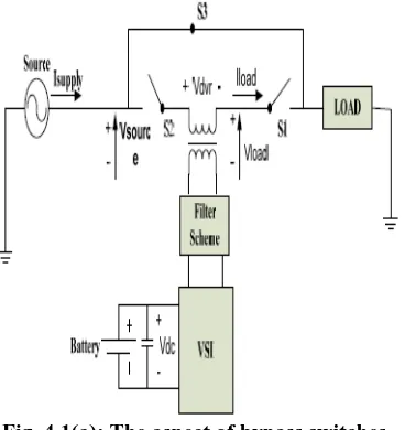
In protection mode scheme, the bypass switch can be used as a protection device to protect DVR from the over current in the load side due to short circuit on the load or large inrush currents. The DVR can be protected by the action of the bypass switches by supplying another path for current as shown in Figure 4.1(a).
Fig. 4.1(a): The aspect of bypass switches.
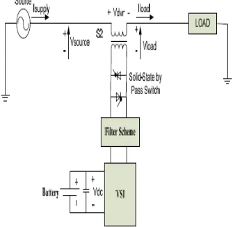
In standby mode (VDVR = 0), as shown in Figure 4.1(b). The injection transformer’s low voltage winding is
shorted through the inverter. No switching of semiconductors occurs in this mode of operation because the individual inverter legs are triggered such as to establish a short-circuit path for the transformer connection. Therefore, only the comparatively low conduction losses of the semiconductors in this current loop contribute to the losses. The DVR will be most of the time in this mode. In the operation of DVR during standby mode, two upper IGBT’s in each phase of the inverter remains turned off while the two lower IGBT’s turned on. A short circuit across the secondary (inverter side) windings of the series transformer through filter is obtained eliminating the use of bypass switches. The DVR goes into injection mode (VDVR > 0) as soon as the sag is
263 | P a g e
possibility of compensating voltage sag. The available voltage injection strategies are pre-sag, phase advance and in phase method.
Fig. 4.1(b): Standby Mode.
V. DVR Compensation Techniques
The methods for injection of missing voltage can be elaborated into pre sag compensation, in-phase compensation and phase advance or minimum energy compensation.
5.1 Pre-Sag Compensation:
In Pre-Sag compensation, it is important for both magnitude and the phase angle to be compensated. The different between the pre-sag and during the sag voltage are detected by the DVR and it injects the different voltage, Therefore, the amplitude and the phase of the voltage before the sag has to be exactly restored. Figure 5.1 illustrates the pre-sag compensation technique showing before and after the voltage sags.
Fig. 5.1: Pre-sag compensation showing before and after the voltage sag.
5.2 In- Phase Compensation:
264 | P a g e
Fig. 5.2: The diagram of In-Phase Compensation Technique.
5.3 Minimum Energy Compensation:
In the minimum energy compensation only small energy storage is required in the other word this concept does not require any active power. The phasor diagram of the minimum energy compensation is illustrated in Figure 5.3. In this compensation method the injected voltage is quadrature with the load current.
Fig. 5.3: Minimum Energy Compensation Technique.
VI. CONTROL STRATEGIES IN DVR
The aim of the controlscheme is to maintain constant voltage magnitude at the point where a sensitive load is connected under systemdisturbances. The control system only measures the RMS voltage at the load point, i.e., no reactive powermeasurements are required. The control of DVR is very important and it involves detection of voltage sags (start, end and depth of the voltage sag) by appropriate detection algorithms which work in real time. Thevoltage sags can last from a few milliseconds to a few cycles, with typical depths ranging from 0.9 p.u. to 0.5 p.u.of a 1-p.u. nominal. Inverter is an important component of DVR. Theperformance of the DVR is directly affect to the control strategy of inverter.
265 | P a g e
I. Linear Control and II. Non Linear Control I. Linear Control:
Linear control is considered as a common method of DVR control. Among the linear control been used in DVR are feed forward control, feedback control and composite control. Feed forward control is a simple method of DVR. The feed forward control technique does not sense the load voltage and it calculates the injected voltage based on the difference between the pre-sag and during-sag voltages. The feedback control strategy measures the load and the difference between the voltage reference of the load and actual load voltage is injected voltage required. Composite control strategy is a control method with grid voltage feed forward and load side voltage feedback, which has the strengths of feed-forward and feedback control strategy, so it can improve voltage compensation effect. The combination with feed forward control can improve the system dynamic response rate, shortening the time of compensation significantly.
II. Non Linear Control:
Due to the usage of power semiconductor switches in the VSI, then the DVR is categorized as non-linear device. In case of when the system is unstable, the model developed does not explicitly control target so all the linear control methods cannot work properly due to their limitation. In the non-linear control following methods are used.
a) Artificial neural network control b) Fuzzy logic control
c) Space Vector PWM control
VII. CONCLUSION
A review of performance of DVR is presented in this paper. It shows that DVR is suitable for voltage sag and swell mitigation by the use of different control techniques. The basic structure of DVR, operating modes, compensation techniques and control strategies are discussed in detail. DVR has the advantage of low cost, requires less computational efforts and its control is simple as compared to other methods. DVR provides simpler implementation for voltage profile improvement. Linear controllers provide simpler operation and less computational efforts when compared to other methods.
REFERENCES
[1] K.R. Padiyar “Facts controllers in power transmission and distribution” new age international (P) Ltd
publishers, 2007.
[2] Masoud Aliakbar Golkar, “Power Quality in Electric Networks: Monitoring and Standards” the second world engineering conference, pp. 137-141 July 2002.
266 | P a g e
[4] C. Alvarez, J. Alamar, A. Domijan Jr., A. Montenegro, and Song, “An investigation toward new technologies and issues in power quality,” in Proc. 9th Int. Conf. Harmon. Qual. Power, vol. 2, pp. 444– 449, 2000.
[5] Bingsen Wang, Giri Venkataramanan and Mahesh Illindala, “Operation and Control of a Dynamic Voltage Restorer Using Transformer Coupled H-Bridge Converters”, IEEE transactions on power electronics, vol. 21, pp. 1053-1061, July 2006.
[6] Ghosh, A. and G. Ledwich, 2002. Compensation of Distribution System Voltage Using DVR, IEEE Trans on Power Delivery, 17(4): 1030-1036.
[7] Li, B.H., S.S. Choi and D.M.Vilathgamuwa, 2001. “Design consideration of the line side filter used in the dynamic voltage restorer,” IEE Proc. -Generation Transmission Distribution, 148(1).
[8] Li, G.J., X.P. Zhang, S.S. Choi, T.T. Lie and Y.Z. Sum, 2007. Control strategy for dynamic voltage restorers to achieve minimum power injection without introducing sudden phase shift”IET Generation, Transmission and Distribution, 1(5): 847-853.
[9] Seung Ki Sul, 2004. “A novel control method for the compensation voltages in DVR”Applied power electronics conference and Exposition. Volume-1.
[10] Chi Jen Huang, 2003. “Design of DVR with disturbance filtering enhancement” IEEE Transactions on Power Electronics
[11] Rosli omar, N. A. Rahim, “Modelling and Simulation for voltage sags/swells mitigation using DVR”, Power Engineering Conference, 2008