268 | P a g e
STUDY OF DESIGN OF COMPACT HYDRAULIC
PRESS MACHINE FOR ROCK DRILL COMPONENTS
Nawale Sagar
1Patil More Tejas
2Gavande Ajinkya
3Mistry Girish
4Vidyasagar Gavali
5, Chandrashekhar K. Patil
61,2,3,4
B.E. Scholars, Pune University (India)
5
Assistant Professor Mechanical Dept.BVCOE & RI Nashik (India)
6
Principal BVCOE & RI Nashik (India)
ABSTRACT
In an attempt to alleviate the problem of the dearth of equipment in our laboratories in most of our higher
institutions, a 300bar hydraulic press was desgined, constructed and tested using locally sourced materials. The
principal parameters of the design included the maximum load, the distance the load resistance has to move
(piston stroke, 300 mm), the system pressure, the cylinder area (piston diameter = 150 mm) and the volume flow
rate of the working fluid. The major components of the press designed includes the cylinder and piston
arrangment, the frame and the hydraulic circuit.
The machine was tested for performance with a load of 10 kN provided by two compression springs of constant
9 N/mm each arranged in parallel between the upper and lower platens and was found to be satisfactory. The
cost estimate for the hydraulic press was N47,890.00 (US$320) at prices in Benin City, Nigeria, as at the time of
press manufacture.
I. INTRODUCTION
The development of engineering over the years has been the study of finding ever more efficient and convenient
means of pushing and pulling, rotating, thrusting and controlling load, ranging from a few kilograms to
thousands of tons (Sumaila 2002). Presses are widely used to achieve this. Presses, as defined by Lange (1975),
are pressure exerting machine tools. They can be classified into three principal categories as: hydraulic presses
which operate on the principles of hydrostatic pressure, screw presses which use power screws to transmit
power and mechanical presses which utilize kinematic linkage of elements to transmit power (Niebel et al. 1989;
Degarmo et al. 1997; Sharma 2005). In hydraulic press, the force generation, transmission and amplification are
achieved Department of Production Engineering, University of Benin, Benin City, Edo State, Nigeria. Using
fluid under pressure. The liquid system exhibits the characteristics of a solid and provides a very positive and
rigid medium of power transmission and amplification. In a simple application, a smaller piston transfers fluid
under high pressure to a cylinder having a larger piston area, thus amplifying the force. There is easy
transmissibility of large amount of energy with practically unlimited force amplification. It has also a very low
inertia effect.
A typical hydraulic press consists of a pump which provides the motive power for the fluid, the fluid itself
which is the medium of power transmission through hydraulic pipes and connectors, control devices and the
269 | P a g e
2002; Sharma 2005). The main advantages of hydraulic presses over other types of presses are that they providea more positive response to changes ininput pressure, the force and pressure can accurately be controlled, and
the entire magnitude of the force is available during the entire working stroke of the ram travel. AU J.T. 14(3):
196-200 (Jan. 2011) Technical Report 197 Hydraulic presses are preferred when very large nominal force is
required (Lange 1975). The hydraulic press is an invaluable equipment in the workshop and laboratories
especially for press fitting operations and for the deformation of materials such as in metal forming processes
and material testing for strength. A look at the workshop in Nigeria reveals that all such machines are imported
into the country. Therefore, it is intended here todesign and manufacture a press, which is low cost and
hydraulically operated using locallysourced materials. This will not only help to recover the monies lost in the
form of foreignexchange, but will enhance the level of our local technology in the exploitation of hydraulic fluid
power transmission.
1.1 Problem Defination
The problem in the pressing of small components of rock drill machine is that it has to be pressed on high
capacity machine which required large amount of power supply , greater pump capacity.Which increases the
machine size , its initial as well as running cost.
1.2 Solution
1)To Reduce the Floor space area required in the Industry . 2)The press is Compact and Easy to assemble and dismantle .
3)Small parts of Rock drill machines can be easily pressed using this machine .
1.3 Objectives
1)Manual and hydraulic control
2)With cylinder extension
3)Pressure gauge in casing
4)Supplied with hoisting eye
5) Compact mode
II. THEORY OF HYDRAULIC PRESS
2.1 Principle:
The hydraulic press depends on Pascal's principle: the pressure throughout a closed system is constant. One part
of the system is a piston acting as a pump, with a modest mechanical force acting on a small cross-sectional
area; the other part is a piston with a larger area which generates a correspondingly large mechanical force. Only
small diameter tubing (which more easily resists pressure) is needed if the pump is separated from the press
cylinder.Pascal's law: Pressure on a confined fluid is transmitted undiminished and acts with equal force on
equal areas and at 90 degrees to the container wall A fluid, such as oil, is displaced when either piston is pushed
inward. Since the fluid is incompressible, the volume that the small piston displaces is equal to the volume
displaced by the large piston. This causes a difference in the length of displacement, which is proportional to the
270 | P a g e
moved a large distance to get the large piston to move significantly. The distance the large piston will move isthe distance that the small piston is moved divided by the ratio of the areas of the heads of the pistons. This is
how energy, in the form of work in this case, is conserved and the Law of Conservation of Energy is satisfied.
Work is force applied over a distance, and since the force is increased on the larger piston, the distance the force
is applied over must be decreased.Bramah's basic idea is also exploited in hydroforming.
2.2 Working
Since the hydraulic press works on the basis of Pascal's Law, its working is similar to the one of the hydraulic
system. A hydraulic press consists of basic components used in a hydraulic system that includes the cylinder,
pistons, the hydraulic pipes, etc.The working of this press is very simple. The system comprises of two
cylinders, the fluid (usually oil) is poured in the cylinder having a small diameter. This cylinder is known as the
slave cylinder.The piston in this cylinder is pushed so that it compresses the fluid in it that flows through a pipe
into the larger cylinder. The larger cylinder is known as the master cylinder. The pressure is exerted on the
larger cylinder and the piston in the master cylinder pushes the fluid back to the original cylinderThe force
applied on the fluids by the smaller cylinder results in a larger force when pushed in the master cylinder. The
hydraulic press is mostly used for industrial purposes where a large pressure is required for compressing metals
into thin sheets. An industrial hydraulic press uses the material to be worked upon along with the help of the
press plates to crush or punch the material into a thin sheet.
Fig.No.1-Pascal’s law
2.3. Typesof Hydraulic Press:
There are many different types of hydraulic presses catering to the various requirements of industries. Some of
them are as follows:
1)Arbor presses:These presses are usually used when the work involved is not of a heavy- duty nature. These
presses come in a variety of sizes and specifications. But compared to other hydraulic presses, they do not
compress large amounts of pressure required to generate more output. Arbor presses are used in processes like
271 | P a g e
2)Laminating presses:Unlike other hydraulic presses that are operated automatically, these presses make use
of manual labor. Laminating presses have two openings that are known as plates. One is used for heating
whereas the other is used for cooling. This makes the lamination process comparatively faster. Through these
presses, materials like polymer can be laminated onto paper and metal. In case of laminating presses, the plates
are usually heated with oil or through electricity. A laminating press is also used for common uses such as
laminating the identity cards, certificates and even book covers. In this way, laminating presses facilitates fast
and easy lamination for industrial and domestic needs.
3)C- frame presses: These presses have a 'C' like shape, which is specifically designed to maximize the floor
space for the workers in order to move around easily at the workplace. Unlike other presses that have
multi-processes, the C- frame presses only include a single press application. Its application includes straightening,
drawing and mostly includes assembling work. C- frame presses come in a variety of weights. The C- frame
presses are also available with extra features such as wheel stands and pressure gauges.
4) Pneumatic presses:These presses are the most basic hydraulic presses used in industries because they
compress the air to create a pressure in order to gain movement. The advantage of pneumatic presses is that the
operations are performed fast whereas the disadvantage of this press is that it cannot create extremely high
pressures, as other hydraulic presses are able to create. The pneumatic presses are often used in car and aircraft
brakes system. The industrial uses of pneumatic presses would include assembling, drawing, punching, etc. A
pneumatic press usually requires a full time operator and for the sake of his safety, additional safety accessories
such as electrical safety devices are also included.
5)Power presses:These presses are used in large industries that demand the use of heavy machinery and
equipments. There are 2 kinds of power presses on the basis of the type of clutch used. They are full revolution
and part revolution clutch. In case of a full revolution clutch, the clutch cannot be disrupted until and unless the
crankshaft makes a full revolution. In case of part revolution, the clutch can be disrupted at any time, before or
after the full revolution. Power presses involve a lot of danger because of the heavy operations associated with
it. A lot of safety measures are taken while using power presses.
6)Assembly presses:These presses use the extreme pressure generated by the pistons and the hydraulic fluids to
assemble and maintain the parts.
7)H- frame presses: These presses have a peculiar 'H' shape and are capable of handling more that one press
application.
2.4. Properties And Specification
2.4.1Properties
1)Manual and hydraulic control
2)With cylinder extension
3)Pressure gauge in casing
4)Supplied with hoisting eye
5)Pump with year guarantee
272 | P a g e
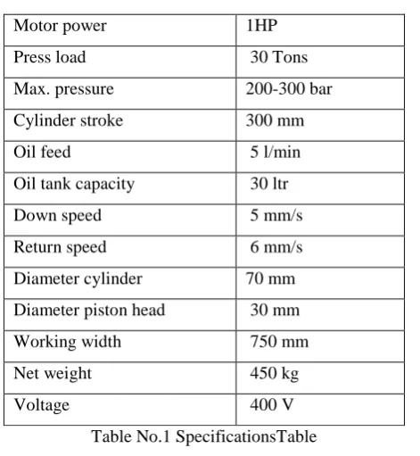
2.4.2 Specification
Motor power 1HP
Press load 30 Tons
Max. pressure 200-300 bar
Cylinder stroke 300 mm
Oil feed 5 l/min
Oil tank capacity 30 ltr
Down speed 5 mm/s
Return speed 6 mm/s
Diameter cylinder 70 mm
Diameter piston head 30 mm
Working width 750 mm
Net weight 450 kg
Voltage 400 V
Table No.1 SpecificationsTable
2.5 Safety Measures And Benefits Of The Hydraulic Press
2.5.1Safety Measures
As of today, hydraulic presses are available in both the categories, i.e., automatic and manually operated. In case
of manually operated hydraulic presses, many safety measures have to be taken such as using interlocking and
barrier guards.
2.5.2Benefits Of the Hydraulic Press
Unlike their mechanical counterparts, hydraulic presses can compress any material to a full extent. Also,
hydraulic presses take only half of the space that the mechanical ones take because they have the ability to
compress a large pressure in a cylinder having a less diameter.
2.6 The Function Of The Hydraulic System
Hydraulic systems convert electrical energy into hydraulic energy, which in turn is transformed into mechanical
energy with the aid of the individual hydraulic cylinders inside the press. The hydraulic fluid in the cylinders
actuates the press slide as follows:
1) Forces are generated through the action of the hydraulic fluid.
2) Displacements are achieved by the supply of hydraulic fluid.
3) Press (slide) speed is proportional to volumetric flow rates.
4) Forward and reverse motions are controlled by the direction of fluid flow.
III. DESIGN METHODOLOGY
Fluid power systems are designed by objective (Sullivan 1975). The primary problem to be solved in designing
273 | P a g e
principal parameters of the design included the maximum load (300 kN), the distance the load resistance has tomove (piston stroke,150 mm), the system pressure, the cylinder area (piston diameter = 100 mm) and the
volume flow rate of the working fluid. The critical components that require design included the hydraulic
cylinder, the frame, the hydraulic circuit.
3.1. Component Design
3.1.1. Hydraulic Cylinder:
Hydraulic cylinders are tubular in structure in which a piston slides when hydraulic fluid is admitted into it. The
design requirement includes the minimum wall thickness of the cylinder, the end cover plate, the flange
thickness and the specification and selection of number and sizes of bolts. The output force required from a
hydraulic cylinder and the hydraulic pressure available for this purpose determine the area and bore of the
cylinder and the minimum wall thickness. From Khurmi and Gupta (1997), the maximum wall thickness, t of a
pressure vessel (hydraulic cylinder) was computed to be0.0167 m from Eq. (1) below:
t = Ri{[ δ t/( δ t- 2p)]1/2 - 1}, (1)
where:
Ri= internal radius of cylinder (m), 50 x10-3 m;
p = Internal fluid pressure (N/m2), 3.82;
δt= Tangential stress ( N/m 2
), 480 × 106.
Therefore a minimum wall thickness of 0.017 m was considered adequate for the design.
3.1.2. Cylinder End-Cover Plate:
The thickness T, of the end-cover-plate, which is supported at the circumference by bolts and subjected to an
internal pressure uniformly distributed over the area, is given by Eq. (2) from Khurmi and Gupta (1997), as:
T = KD(P/ δt)1/2, (2)
where:
D = Diameter of end cover plate (m), 0.1;
K = Coefficient depending upon the material ofplate, 0.4, from Khurmi and Gupta (1997);
P = Internal fluid pressure (N/m2), 38.2;
δt= Allowable design stress of cover. Plate material, 480 N/m2;from which the thickness of the plate was
obtained to be 0.0118 m.
3.1.3.Bolt:
The cylinder cover may be secured by means of bolts or studs. The possible arrangement for securing the cover
with bolts is shown in Fig. 2. In order to find the correct size and number of bolts, n, to be used, the following
Eq. (3) was used as adopted from Khurmi and Gupta (1997):
(πDi2/4)P = (πdc2/4)δtbn, (3)
where;
P = Internal fluid pressure (N/m2);
Di= Internal diameter of cylinder (m);
274 | P a g e
δtb= Permissible tensile strength of the bolt.If the size of the bolt is known, then, the number of bolts can be computed from Eq. (3) and vice versa.
However, if the value of n as obtained from Eq. (3) above is odd or a fraction, then the next higher even number
is adopted. The number of bolts was computed to be 3.108, hence four bolts were chosen. The tightness of the
joint between the cylinder and the end-cover-plate depends on the circumferential pitch, Dp, of the bolt, which
was obtained as 0.0191 m from Eq. (4):
Dp= Di + 2t +3Dc, (4)
where:
t = thickness of cylinder wall (m), 17 × 10-3.
3.1.4. Cylinder Flange:
The design of cylinder flange is essentially to obtain the minimum thickness tf, of the flange, which may be
determined from bending consideration. There are two forces in action here, one due to fluid pressure and the
other that tends to separate the flange due to sealing which has to be resisted by the stress produced in the bolts.
The force trying to separate the flange was computed to be 58.72 kN from Eq. (5):
F = (π/4)D12P, (5)
where:
D1 = outside diameter of seal, 134 × 10-3 m.
3.1.5. Flange Thickness Determination:
The thickness of the flange, tfmay be obtained by considering the bending of the flange about section A-A being
the section along which the flange is weakest in bending (Fig. 3). This bending is brought about due to the force
in two bolts and the fluid pressure inside the cylinder.Therefore, Eq. (6) gave a flange thicknessof 0.0528 m:tf=
(6M)/(b δf), (6)
where:
b = Width of flange at section A-A, 22.2×10⁻³ m;
δf = Shear stress of flange material, 480N/m2;
M = Resultant bending moment, 5,144.78 Nm.
3.1.6. Piston:
The required piston rod column size necessary to sustain applied load and which is in alignment with the center
line the cylinder bore is influenced by the strength of the rod material, the force applied to the rod column in
compression, the mounting situation of the cylinder itself and the stroke over which the load is to be applied.
The procedure for computing piston rod column size and cylinder lengths under end AU J.T. 14: 196-200 (Jan.
2011) Technical Report 199 thrust condition was accomplished using the procedure suggested by Sullivan
(1975). By this the size of the piston rod of diameter not less than 0.09 m was considered adequate for the
design.
3.1.7. Selection of Seals:
Seals are used to prevent internal and external leakages in the system under varying operating conditions of
pressure and speed. Static seal selected uses the
groove and ring principle to affect a seal. The groove dimension is calculated such that the Oring selected is to
275 | P a g e
in the selection of static seal is to specify the groove such that an O-ring can be compressed in one direction andexpanded in another, Therefore; a
grove dimension of 4 mm × 3 mm was specified for the seal.
3.2. Frame Design
The frame provides mounting points and maintains proper relative positions of the units and parts mounted on it
over the period of service under all specified working conditions. It also provides general rigidity of the machine
(Acherkan 1973). The design consideration is that of direct tension imposed on the pillars. Other frame
members such as the platens (as in our case) are subjected to simple bending stresses.
Fig.No.2-Frame design
3.2.1. Platen:
The upper and lower platens provide point of direct contact with the object being compressed. Hence, they are
subjected to pure bending stress due to an equal and opposite couple acting in the same longitudinal plane. The
design consideration is essentially for bending and consists primarily upon the determination of the largest value
of the bending moment (M) and shear force (V) created in the beam which was found to be 45 kN/m and 150
kN, respectively. These were computed using the procedure adopted from Beer and Johnston (1992).
3.2.2. Section Modulus:
The values of Vand Mobtained facilitate the computation ofthe modulus of section of the platens. Thisgives the
minimum depth (thickness) d, andwas computed to be 0.048 m from Eq. (7): d = [(6M)/(δb)]1/2, (7)
where;
M = Maximum bending moment, 45 kN/m;
b = 600 × 10-3 m;
δ = 480 × 106 N/m2.
3.2.3. Pump:
The initial parameter in the design is to estimate the maximum fluid discharge pressure required at the cylinder
and a factor is then added to account for frictional loss in the system. This was obtained to be 47.16 × 10⁶
276 | P a g e
The pumping action is actuated by a lever system. The actual length of the lever was obtained to be 0.8 m. Thiswas calculated by assuming a maximum theoretical effort and taking moment about the fulcrum.
3.4. Die
Die is an integral part of any manufacturing process which enables the desired shape that one require. Here for
the experimental purpose a compound die have been used which produces a washer from the strip of sheet
metal. The dimensions of the outcome washers are as follow. Outer diameter = 30 mm , Inner diameter = 10
mm. A blanking die produces a flat piece of material by cutting the desired shape in single operation. The
finished part is reffered to as a blank. Generally a blanking die may only cut an outer contour of part, often used
for parts with no internal features.
3.5 Bed
Bed is a plate on which the die is supposed to held. It is used for mounting the die on support frame at desired
position. Figure 3 shows the design of bed where the holes produced on the sides shows the support plate to be
clamped on support frame.
Fig.No.3-Bed design
IV. ADVANTAGES AND DISADVANTAGES
4.1 Advantages
1) Compact in shape and size.
2) Equipment handling is easy.
3)The press machine less bulky compare to other machine.
4) The simplicity and easy to repair design makes it really cheap
4.2 Disadvantages
1) Only small component manufacturing.
V. CONCLUSION
A 300bar hydraulic press was designed, manufactured, and calibrated. The machine was tested to ensure
conformability to design objectives and serviceability. The machine was found to be satisfactory at a test load of
277 | P a g e
Thus here a hydraulic system is used to develop a press. The press will be useful for massproduction of rockdrill components. This may increase the productivity and increases the accuracy of the production. Event the
press can be completely automized by using the concept of ectro-hydraulics. Direction control valve can be
solenoid acted to make the system close loop which may lead to higher production rate.
REFERENCES
www.google.com
[1] Acherkan, N. 1973. Machine tool design. Vol. 3, Mir Publ., Moscow, Russia.
[2] Beer, F.P.; and Johnston, E.R., Jr. 1992. Mechanics of materials. 2nd ed., McGraw- Hill, London, England,
UK.
[3] Dagwa, I.M.; and Ibhadode, A.O.A. 2005. Design and manufacture of automobile diskbrake pad test rig.
Nigerian Journal of Engineering Research and Development 4(3): 15-24.
[4] Degarmo, E.P.; Black, J.T.; and Kohser, R.A. 1997. Materials and processes inmanufacturing. 8th ed.,
Prentice-Hall of India, New Delhi, India, pp. 546-52.