[Lazar et al., 6(11): November, 2019]
ISSN 2349-0292
Impact Factor 3.802
GLOBAL JOURNAL OF ADVANCED ENGINEERING TECHNOLOGIES AND
SCIENCES
POSSIBILITY OF HYDROGEN SEPARATION FROM SYNTHESIS GAS BY USING
THE ABSORPTION PROCESS
Marián Lázár*, Romana Dobáková*, Tomáš Brestovič*, Natália Jasminská*, Lukáš Tóth*
*
Department of Power Engineering, Faculty of Mechanical Engineering, Technical University of
Košice, 042 00 Košice, Slovak Republic
DOI: 10.5281/zenodo.3548212
ABSTRACT
The present paper deals with a possibility of hydrogen separation from synthesis gas by using the absorption process. The composition of the synthesis gas mixture generated in the process of high-temperature gasification and the possibility of its recovery are analyzed. The risks affecting the life of the metal hydride alloy is also taking into account. The possibility of increasing the hydrogen concentration in the gaseous mixture is exploited by using series-connected pressure vessels and by the gravitational effect. In the conclusion, there is a proposal of connection of separation column applying the principle of hydrogen absorption using MH alloys.
KEYWORDS: separation, syngas, hydrogen.
INTRODUCTION
Within the processing of waste with a high content of organic matter, the expected product of the high-temperature processing is synthesis gas, i.e., syngas. This product, rich in hydrogen and carbon monoxide, has the potential of energy recovery [1, 2].
Syngas may supposedly be used in metallurgy as well, for example, in the process of reduction of metals. If the gas mixture contains a considerable amount of hydrogen and after it is successfully separated, it might also be used in the automotive industry. An important factor, however, is the high purity of the separated hydrogen with regard to the efficient operation of fuel elements.
The assumption of the potential use of hydrogen generated in the process of high-temperature waste processing in a plasma reactor is based on the volume fraction of hydrogen contained in the analysed mixture of gases, hydrogen separation efficiency, and the resulting purity of this gas. Processing of various types of waste with a high content of the organic fraction and with humidity acceptable for the given technology (< 15 %) facilitates that the resulting product of high-temperature decomposition is a hydrogen-rich gas product (synthesis gas). This has also been confirmed by the results of investigations performed by many research teams which reported to achieve as much as 50 % content of hydrogen in the synthesis gas by processing the charge with a high content of the organic component. Tab. 1 presents the summary of the composition of the synthesis gas obtained by processing various types of waste products in a plasma reactor.
Table 1. Summary of the composition of synthesis gases as products of the gasification of various waste types [1, 2]
Component
Composition of collected synthesis gas specimens
RDF* vol. %
Waste brown coal vol. %
Carbon sludge vol. %
Municipal
solid waste vol. %
Methane 0.26 0.48 4.77 3.84
Hydrogen 50.9 44.8 32.9 48.9
Oxygen 0.03 0.24 0.02 0.11
Nitrogen 4.25 9.23 20.1 6.61
Carbon dioxide 1.1 0.68 3.35 1.66
Carbon monoxide 43.5 44.4 43.6 37.1
Ethene 0.006 0.043 0.001 0.49
Ethane 0.001 0.0036 0.001 0.031
[Lazar et al., 6(11): November, 2019]
ISSN 2349-0292
Impact Factor 3.802
Sum of C3 hydrocarbons 0.005 0.0027 0.001 0.04
Sum of C4 hydrocarbons 0.001 0.0032 0.001 0.004
Sum of C5-8 hydrocarbons 0.001 0.05 0.01 0.12
Heat capacity (MJ∙m-3) 11.10 10.75 9.07 12.31
Expected volumeproduction (m3∙kg-1) 1.843 0.352 1.419 0.973
PROPOSED SEPARATION COLUMN
With regard to the particulate matter content in the syngas flow, designing the hydrogen separation apparatus requires the pre-treatment of the gas mixture to be processed. The first step is the removal of the particulate matter in a dry or wet cleaning process. Subsequently, after the removal of acidic gases and vapours, as well as aqueous vapour, from the mixture of gas components formed in the process of high-temperature waste processing, the resulting product is suitable for further processing. The cleaned mixture of hydrogen, carbon monoxide and dioxide, methane, nitrogen, and higher hydrocarbons, present there in relatively small amounts, represents an interesting source of energy as it contains chemically bound energy; however, the process of final purification thereof still imposes certain risks.
As stated by many authors, high contents of CO, CO2, or H2O and O2 in a gas mixture have negative effects on
the metal hydride which may, as a result of the effects of these gas components, degrade and stop absorbing hydrogen within certain period of time. This will disable the absorption-desorption cycle and, as a result, require the regeneration of the used alloy or a complete replacement thereof.
In order to avoid this, the attention was paid to increasing the concentration of hydrogen in the gas mixture entering the metal hydride tank. Simple separation columns were proposed while applying the principle of separating individual gas components through gravitation. These proposals were drawn up while considering an important factor of achieving such velocity of the gas mixture entering the separation column which would prevent mixing of individual gas components, or only to the minimum extent.
PROPOSED PRE-SEPARATION COLUMN AIMED AT INCREASING THE
HYDROGEN CONCENTRATION IN THE RESULTING GAS MIXTURE ENTERING
THE STAGE OF ABSORPTIVE CLEANING
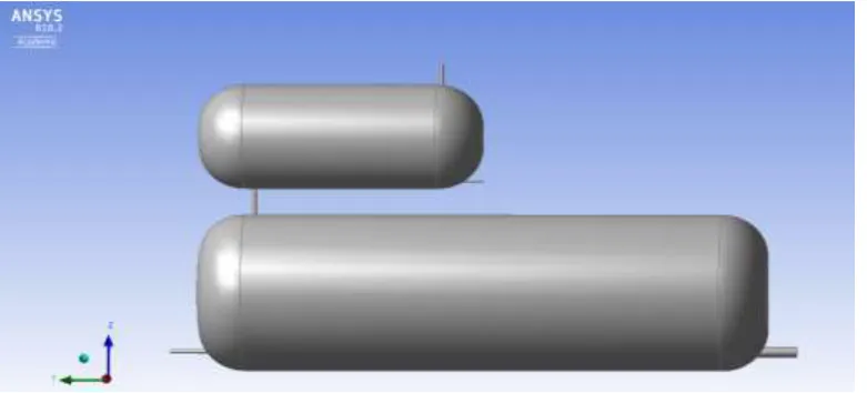
The analysis of the syngas composition (Tab. 1) was followed by the creation of the numerical model. The model consisted of two horizontally positioned pressure tanks ̶ PT-1 and PT-2 (Fig.1). The entry of the gas mixture was projected in the lower part of the lower tank (PT-1) through the opening on the right side. The exhaust of heavier components of the gas mixture, such as CO and CO2, was projected through the opening located opposite the
opening used for additional supply of the gas mixture to the system (outlet opening in the lower part of the lower tank located on the left side of this tank). The gas mixture with a higher hydrogen concentration is supplied to the pressure tank (PT -2) through a thin pipe located between two pressure tanks. The internal volume of the tanks is 0.041 m3.
[Lazar et al., 6(11): November, 2019]
ISSN 2349-0292
Impact Factor 3.802
The pressure of the gas mixture (syngas) at the inlet to the tank was defined as 3 MPa. The velocity of the syngas flow is 1 m∙s-1. The outlet openings on the pressure tanks were preset to the “open” mode, at the zero relativepressure. The composition of the gas mixture corresponded to the following values: H2 = 45 % v/v; CO = 40 %
v/v; CO2 = 10 % v/v; and CH4 = 5 % v/v.
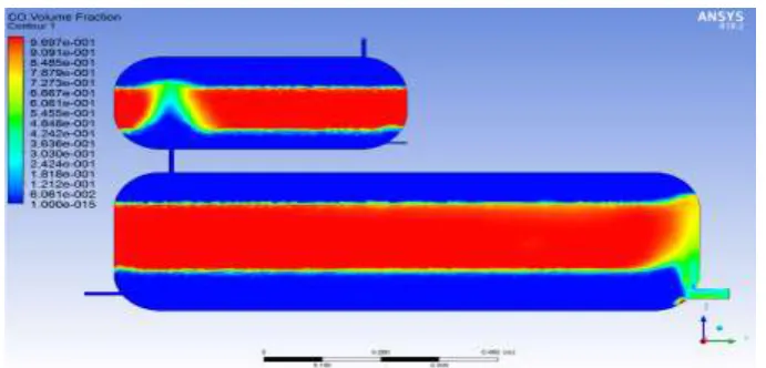
The layering of individual gas components of the synthesis gas after 200 seconds is shown in Fig. 2 to 5.
Figure 2. Hydrogen layering after 200 s, at the mixture flow velocity of 1 m∙s-1.
Figure 3. Layering of carbon dioxide after 200 s, at the mixture flow velocity of 1 m∙s-1.
[Lazar et al., 6(11): November, 2019]
ISSN 2349-0292
Impact Factor 3.802
The problematic gas components of syngas that cause the degradation of the metal hydride properties (CO, CO2,etc.) concentrate in the lower pressure tank (PT-1). The pressure tank PT-2 is primarily filled with hydrogen and, in a lower amount, carbon monoxide. The presence of carbon dioxide in the pressure tank PT-2 may be attributed to the presence thereof on this tank in the initial state. With regard to only a low content of methane in syngas generated in the process of plasma gasification and melting, its presence in the pressure tank PT-2 is negligible. As may be seen in Fig. 5, at second 200, methane does not penetrate to the higher pressure tank.
Figure 5. Layering of carbon monoxide after 200 s, at the mixture flow velocity of 1 m∙s-1.
On the basis of the analysis of the data obtained from the analysis model, it may be stated that at the mixture flow velocity of 1 m∙s-1 individual the gas mixture components form separate layers.
PROPOSED ABSORPTION-BASED SEPARATION UNIT
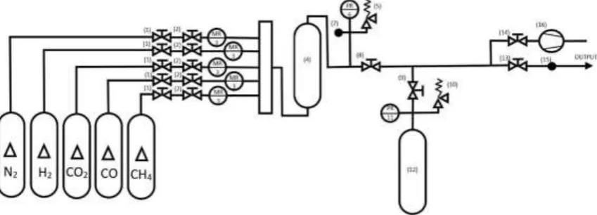
The experimental model of the apparatus used for the separation of hydrogen from the synthesis gas during the absorption process is based on the preparation of and mixing different gas mixtures free of any particulate matter and aqueous vapours. The desired contents of individual gas components in the resulting mixture were achieved by using the pressure regulators (1, 2) and mass flow meters (3) while the gas sources will be the pressure tanks containing pure gases.
Figure 6. Scheme of the separation column applying the principle of hydrogen absorption using the MH material.
[Lazar et al., 6(11): November, 2019]
ISSN 2349-0292
Impact Factor 3.802
The pressure at the outlet from the mixing chamber is regulated by the BD Sensors DX9-DMP 331i pressure gauge (6). The sampling point (7) is used to collect samples and verify the composition of the prepared mixture. The escape valve (5) prevents from a potential pressure increase above the value of the permissible limit applicable to the given module.The process of hydrogen absorption into the intermetallic structure of the alloy runs in the stainless steel pressure tank filled with a suitable metal alloy (12). The supply and removal of heat from the process of absorption and desorption is facilitated by the spiral cooler located inside the stainless steel pressure tank while the cooler is surrounded by the metal alloy.
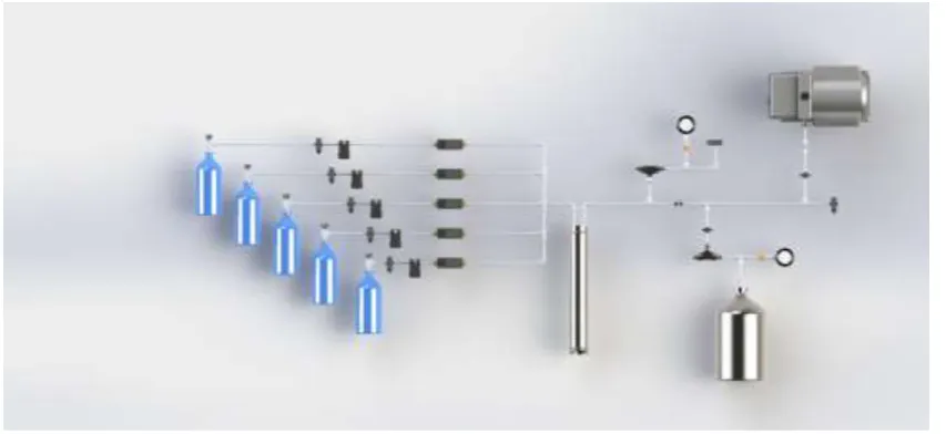
The sampling point (15) facilitates the collection of the gas mixture samples at the outlet from the apparatus. The exhaust of the atmosphere from the MH tank prior to hydrogen desorption is carried out by means of the rotary air pump (16). A 3D scheme of the separation unit is shown in Fig. 7.
Figure 7. 3D scheme of the separation unit.
The flow may be regulated by mixing gases while applying the partial pressures:
toti i i
i i
z x
p
p
z x
(Pa) (1)where Δpi is the partial pressure of the ithcomponent of the mixture (Pa); zi is the mean compressibility factor of
the ithcomponent of the mixture (1); x
i is the volume fraction of the gas in the mixture (1); and ptot is the total
absolute pressure of the mixture of gases (Pa).
When the gases are mixed while applying the partial pressure, it is necessary to maintain isothermal conditions during the filling; this requires longer time due to balancing the temperature differences between individual feedings of mixture components.
CONCLUSION
The designed device intended for hydrogen separation using MH materials will facilitate the extension of the research portfolio of the university department with very specific areas, such as final purification of gaseous mixtures formed in various processes within the manufacture segment. By constructing a prototype laboratory device, the possibilities of testing the applicability of MH alloys, in the area of hydrogen separation from a mixture of gaseous components, will be opened. Research on this area will enable monitoring the operation of the proposed separation column, which will reveal the positives as well as shortcomings of the proposed solution.
ACKNOWLEDGEMENTS
[Lazar et al., 6(11): November, 2019]
ISSN 2349-0292
Impact Factor 3.802
REFERENCES
1. M. Lázár, M. Čarnogurská, T. Brestovič, “High temperature waste treatment technologies,” Košice: SjF, TUKE 2018. 201 p. ISBN 978-80-553-2756-3.
2. M. Lázár, M. Lengyelová, M. Čarnogurská, Ľ. Širillová, “Refuse - derived fuel energy recovery by plasma technology,” Transactions of the VŠB - Technical University of Ostrava. 2014, 60(1), 69-76. 3. M. Lázár, L. Tóth, T. Brestovič, “Syngas purification by using metal hydride alloys,” AIP Conference
![Table 1. Summary of the composition of synthesis gases as products of the gasification of various waste types [1, 2] Composition of collected synthesis gas specimens](https://thumb-us.123doks.com/thumbv2/123dok_us/8682465.1733804/1.595.101.496.607.768/summary-composition-synthesis-gasification-composition-collected-synthesis-specimens.webp)