ISSN: 2231-5381
http://www.ijettjournal.org
Page 1899
Observer Based Feedback Linearization Control of an
Under-actuated Biped Robot
Mchiri Mohamed#1, Trabelsi Karim#2
#Electrical Engineering, National School of Engineering, ENIT
Tunis, 1002, Tunisia
Abstract— This paper deals with the design of a control strategy
that combines a nonlinear observer and a partial feedback linearization controller to stabilize the periodic orbits of an under-actuated three link biped robot. We show first that passive dynamics (non-actuated coordinates) can be linearized and decoupled from the rest of the system by applying a nonlinear feedback. Then, the proposed observer is developed in order to estimate the unmeasured velocity signals of the robot. The convergence of the closed loop system is finally proved. Excellent simulations are included to show the effectiveness of the proposed method.
Keywords— Biped robot, control, feedback linearization,
observer design.
I. INTRODUCTION
The main complexity in bipedal locomotion is the degree of actuation of the robot. Under-actuated robots are systems that regroup fewer control signals than configuration variables. In literature, several methods are developed to control under-actuated mechanical systems including energy-based approaches [1], linearization technique [2], sliding mode control [3]-[5], flatness based approaches [6], and so on. In [7], Spong shows that it is possible to linearize non-actuated coordinates under a condition called Strong Inertial Coupling. This approach provided good results when applying to acrobat robot. However, most of control strategies suppose knowledge of the all state variables vector. In practice, velocity signals are not always measured due to noise that can affect sensors and consequently it is necessary to use an observer in order to estimate velocities from only position measurements and then construct the control law. In recent years, several types of nonlinear observers have been developed for mechanical systems [8]-[11].
Sliding mode observers have been proposed for many mechanical systems [12]-[14]. In [15], a second-order sliding mode observer is designed to estimate velocities of a switched mechanical system. However, the design of the observer requires the knowledge of uncertainties modelling. A step-by-step second-order sliding mode adaptive observer was applied in [16] for continuous signal reconstruction. By assuming that the absolute angular value is not measured, a nonlinear observer has been studied in [14] for the control of a walking biped. The approach has been successfully applied but the difficult is the finding of the observer gains and the uncertainties modelling.
The purpose of this paper is to design a control strategy for controlling three-link under-actuated bipedal locomotion. This strategy incorporates a novel nonlinear observer to estimate the unmeasured velocities and a feedback linearization based control law. We show first that the passive coordinate of the robot can be linearized and decoupled from the rest of the system by using a nonlinear feedback. After then, the observer is proposed to ensure an asymptotic finite-time estimation of velocity signals which are used in the development of the control law. The stability of the overall closed loop system is proved.
The reminder of this paper is structured as follows. Section 2 displays the model of the under-actuated three links biped robot and underlines physical properties of this kind of mechanical systems. In section 3, we consider the control law based on partial feedback linearization technique. Section 4 is devoted to the observer design and the asymptotic convergence analysis. Section 5 illustrates the main results through simulations applied to the robot under consideration. Finally, some conclusions are included in Section 6.
II. UNDER-ACTUATED BIPED ROBOT MODEL
This section presents the model of under-actuated three-link biped robot. The mechanical system is composed of a torso of massMT, hips of massMhand two legs that have equal lengths r and masses m with no ankles and no knees (see figure 1). L designs distance between hips and torso. Initially, three degrees of freedom are obtained from this model. The robot is under-actuated since we have two torques applied between the torso and the legs. It was assumed that the walking cycle consists of successive phases of single support (i.e. one leg is touching the ground) with the impact of the swing leg with the ground. Consequently, the mechanical model of the robot under consideration consists of two parts: a swing phase model described by differential equations and an impact model.
A. Swing phase model
The dynamics of the robot during this phase are described by the following mechanical equation
ISSN: 2231-5381
http://www.ijettjournal.org
Page 1900
where Vector
is composed of the angular positionsT 3 2
1
]
[
which are assumed to be only measured.2
u
represents the applied torques between the two legs. During the swing phase, the matrices M, C, G and B are defined in Appendix 1.Fig.1 Generalized coordinates of the three link biped robot.
B. Impact model
The contact model is generated when the swing leg touch the walking surface. Thus, two Cartesian coordinates
)
z
,
z
(
1 2 are added to Cartesian coordinates of the end of the stance leg and then we have five degrees of freedom of the biped. The impact is considered as a contact between two rigid bodies. At each impact time, the impact forces are given by impulses. Consequently, jumps are allowed in the velocity signals of the biped robot where configuration variables or angular positions remain constant in each impact. With these considerations, the impact model has the formext e
e e
e e e e e e
e(q ).q C (q ,q ).q D (q) B (q ).u F
D (2)
where
q
e
[
1,
2,
3,
z
1,
z
2]
Tis the vector of thegeneralized coordinates and
F
extis the external forces actingon the biped at the contact point with the surface.
Let the notation
(.)
(resp.(.)
) designs variable or time just after (resp. just before ) impact. As mentioned before, during the impact, angular positions remain continuous, i.e.
ee
q
q
, however, an instantaneous change in the velocities is obtained due to impulsive forces. The relation between the post-impact and the pre-impact can be given by the following relationext e
e e
e(q ).(q q ) F
D (3)
where
t t ext
ext F ( )d
F . We suppose here that the
stance leg detach from the surface of contact without interaction. Thus, the external forces that act the pivot point are equal to zero and for that we consider only the external forces that act at the end of the swing leg. To determine
F
ext,we should consider constraints on Cartesians coordinates at the end of the swing leg. These constraints are given by:
0 ) cos( . r ) cos( . r z
d ) sin( . r ) sin( . r z ) q (
2 1
2
2 1
1
e (4)
where d is the length of one biped step. The evaluation of first derivative of (4) gives
0 q ). q (
J e e (5)
and
N T T ext J (q).
F (6)
where J is the Jacobian matrix of constraints given by (4) and
N T
,
are respectively the tangent and normal forces applied at the end of the swing leg. The Jacobian matrix is given by:
1 0 0 1 0 0 ) sin( . r
) cos( . r ) sin( . r
) cos( . r q ) q ( J
2 2 1
1 e
e (7)
Finally, taking into account these considerations, the impact model corresponds to the following system
.
0 q ). q ( J
). q ( J ). q ( J ) q q ).( q ( M
e e T
N T e T e
T e e e e
(8)
From (8), the post-impact velocity vector is computed as a function of pre-impact velocity vector using the following relation
1 T 1 ee T 1 e
e
[
I
M
.
J
.(
J
.
M
.
J
)
J
].
q
q
(9)where I is the 3 by 3 identity matrix. All matrices corresponding the impact phase are defined in Appendix 2.
C. State representation
Let x(q,q) , x (q,q)
, x (q,q) and
i
t
designs an impact time. For eacht
t
i,
t
i1
, the continuous dynamics of model (1) can be rewritten asu
).
x
(
g
)
x
(
f
:
]
u
).
q
(
B
)
q
(
G
q
).
q
,
q
(
C
).[
q
(
M
q
x
1
(10)
This continuous motion has some physical properties (as cited in [10]):
(i) M(q) is a definite-positive-symmetric matrix
(ii) There exists a parameterization for matrix C (.,.) such that
,
R
z
,
0
z
)].
q
,
q
(
C
2
/
)
q
(
M
.[
z
T
n(iii) The Coriolis and centrifugal forces matrix C(.,.) verify
n n
R
R
)
y
,
x
(
,
x
).
y
,
q
(
C
y
).
x
,
q
(
C
,ISSN: 2231-5381
http://www.ijettjournal.org
Page 1901
e e
e e
q
q
)
q
(
x
).
q
(
q
q
x
(11)where
) ( . 0
0 )
(
q D R R
q , R is a matrix that corresponds
to the legs permutation equal to:
1 0 0
0 0 1
0 1 0
R , and
]
J
)
J
.
M
.
J
.(
J
.
M
I
[
)
q
(
D
e1 T e1 T 1 .Finally, the overall hybrid model is given by equations (10) and (11), and can be rewritten in the following state-space form
S
x
,
)
x
(
x
S
x
,
u
).
x
(
g
)
x
(
f
x
:
(12)where S is the switching surface (set of points of contact of swing legs with the walking surface).
III. PARTIAL FEEDBACK LINEARISATION BASED CONTROL LAW Consider the continuous part of the dynamics of the biped robot given by system 10 and assume that the vector of configurations (angular positions) can be partitioned into actuated configurations
q
ac
[
q
1,
q
2]
T and non-actuatedconfigurations
q
nac
q
3
3 . Since the robot is underactuated, we assume also that the vector of applied torques is partitioned as u[0,u1], where1 x 2 1
u
.Finally, we assume that all matrices defining the biped model are partitioned as follows (see Appendix 3)
22 21
12 11
M M
M M ) q (
M , where
2 x 2 22 1 x 2 21
2 x 1 12 1 x 1 11
M ; M
M ; M
22 21
12 11
C C
C C ) q , q (
C , where
2 x 2 22 1 x 2 21
2 x 1 12 1 x 1 11
C ; C
C ; C
T2 1 G
G ) q (
G , where
G
1
1x1,
G
2
2x1After partitioning all matrices, the model of underactuated biped takes the form of
1 2 ac 22 nac 21 ac 22 nac 21
1 ac 12 nac 11 ac 12 nac 11
u G q . C q . C q . M q . M
0 G q . C q . C q . M q . M
(13)
Now, we consider the output equation
ac
q
y
(14)y is called collocated output with the input
u
1[7].From the definition of the inertia matrix in Appendix 1, since we have M11MT.l2 0, we may solve for
q
nac inequation (13) as
] G q . C q . C q . M [ M
1
q 12 ac 11 nac 12 ac 1
11
nac
(15)
Now, when substituting (15) into (13), we get
1 ac
AC nac NAC ac
AC).q (C ).q (C ).q (G) u M
( (16)
with the definition of terms of the following system:
1 11 21 2
12 11 21 22
AC
11 11 21 21
NAC
12 11 21 22
AC
G . M M G
) G (
C . M M C
) C (
C . M M C
) C (
M . M M M
) M (
(17)
Since the matrix
(
M
AC)
is positive definite, it is possibleto linearize the non-actuated (passive) configuration of the system dynamics. Therefore, the feedback linearization controller is defined for (16) and given by
1 ac
AC nac NAC 2
AC
).
v
(
C
).
q
(
C
).
q
(
G
)
u
M
(
(18)where
v
2
2 is an additional control input to be defined later. The closed loop system is then given by:
ac 2 ac
1 ac 12 nac 11 2 12 11 nac
q y
v q
] G q . C q . C v . M [ M
1 q
(19)
It is clearly seen from (19) that the vector of actuated configurations is completely decoupled from the vector of non-actuated configurations and linearized second order. Let
T d 2 d 1 T d 2 d 1
d [y y ] [q q ]
y be the vector of reference trajectoriesv2*yd [v2,1*,v2,2*]T, and e[e1 e2]T , the tracking error vector where each component is given by;
2 , 1 i , q q
ei i id (20)
Now, the additional control input
v
2
2 may be chosen component by component as2
,
1
i
,
)
e
.
k
e
.
k
(
*
v
v
2,i
2,i
i,0 i
i,1
i
(21)where coefficients ki,j,i1,2,j0,1, are chosen so that the
two polynomials
s
k
i,0s
k
i,1s
,
i
1
,
2
are Hurwitz. Then,the error system dynamics can be given by:
* v v e 2 2
(22)
ISSN: 2231-5381
http://www.ijettjournal.org
Page 1902
2
,
1
i
,
)
e
.
k
e
.
k
(
e
i
i,0 i
i,1
i
(23)From (23), we can clearly seen that for a suitable choice of coefficients ki,j,i1,2,j0,1 , the error tracking vector converges globally exponentially to zero.
Let Z1 e,
Z
2
e
,
1
q
nac
q
3,
2
q
nac
q
3. So,the complete closed loop system can be written as
1 d 2
2 1
2 1 1 0 2
2 1
Z
y
y
e
)
t
,
,
Z
(
Z
.
K
Z
.
K
Z
Z
Z
(24)
Where
] Z . K Z . K y .[ M M
1
] G q . C [ M
1 .
C M
1 )
t , , Z (
2 1 1 0 d 12 11
1 ac 12 11 2 11 11
(25)
where
20 10 0
0 0
k k
K , and
21 11 1
0
0
k
k
K
.In matrix form, system (24) can be rewritten as
Z
.
C
e
)
t
,
,
Z
(
w
Z
.
A
Z
(26)
where
] Z Z [
Z 2T
T 1 T
, [ 2T]
T 1 T
,
1 0
2 x 2
K K
I 0
A ,
] 0 , I [
C 2x2 , and
)
t
,
,
Z
(
)
t
,
,
Z
(
w
2 .The zero dynamics relative to the output
e
y
y
dis given by)
,
,
0
(
t
w
(27)Or, when replacing Z by zero into (25),
d 11 12 1 ac 12 11 2 11 11
2
y . M M ] G q . C [ M
1 . C M
1
(28)
which is locally stable for the equilibriums (0,0) and (0,).
IV. OBSERVER DESIGN
Let
xˆ
1(
t
),
xˆ
2(
t
)
2x3 denote the estimated position and velocity of system (1), and the estimation errors3 2
1
1(t),e (t),e (t)
e be defined, respectively, by
)
t
(
x
)
t
(
xˆ
)
t
(
e
1
1
1 (29))
t
(
x
)
t
(
xˆ
)
t
(
e
2
2
2 (30)Let the signal
r
(
t
)
n be the sliding surface and defined as)
t
(
e
)
t
(
e
.
)
t
(
r
1
2 (31)where
is a positive scalar to be chosen, under assumption 1, so thatsgn(
r
(
t
))
sgn(
e
1(
t
)),
t
0
, where sgn(.) is thestandard signum function.
Assumption1. The initial conditions of the state vector of the mechanical system (12)
[
q
T(
t
0)
q
T(
t
0)]
T and the control force u(t) are chosen so that the position and the velocity vector are bounded functions of time.By this assumption, and in order to guarantee that
sgn(
r
(
t
))
sgn(
e
1(
t
)),
t
0
, the positive scalar
can be chosen such that
1 2
where
1,
2 are twopositive constants
1,
2 given by 1 1 1,i 1 i ne min e
and
2 2 2,i
1 i n
e max e
. Indeed, using the equation (31), we have
r
(
t
)
.
e
1(
t
)
e
2(
t
)
. Then to make1
sgn(r(t))
sgn(e (t)),
t
0
, we have to proceed as following:- if
e
1
0
r(t)
must be > 0 which means that2
1 2
1
e (t)
r(t)
e (t) e (t)
0
e (t)
and
- if
e
1
0
r(t)
must be < 0 which means that2
1 2
1
e (t)
r(t)
e (t) e (t)
0
e (t)
(becausewe divide by a negative term
e
1
0
).Which, finally, gives 2
1 max
e (t)
e (t)
. Then, after anappropriate choice of the scalar
, we can guarantee that0
t
)),
t
(
e
sgn(
))
t
(
r
sgn(
1
. Moreover, if S designs theset of points
(
e
1,
e
2)
such that the sliding surface r = 0, then S
0,0 .Now, it is assumed that the velocity signal
)
t
(
q
)
t
(
x
)
t
(
v
2
of the hybrid system (12) is not measured and the only available signal is the output vector)
t
(
q
)
t
(
x
)
t
(
y
1
. Let the signalw
(
t
)
3be equal to)
t
(
ISSN: 2231-5381
http://www.ijettjournal.org
Page 1903
asymptotic convergence of
(
e
1(
t
),
e
2(
t
))
to(
0
,
0
)
as
t
. To this end, we propose the following nonlinear observer having y(t) as input vector, w(t) as state vector and the estimated velocity signalvˆ
(
t
)
as output vector:
N
i
,
)
t
(
e
).
(
)]
t
(
e
).
(
)
t
(
w
)).[
t
(
y
,
e
(
Z
)
t
(
w
)
t
(
e
).
(
)
t
(
w
)
t
(
vˆ
)
e
sgn(
e
.
]
u
).
y
(
B
)
y
(
G
vˆ
).
vˆ
,
y
(
C
).[
y
(
M
)
t
(
w
i 1 1
i 1 1 i
i i
1 1
1 3 1 2
1
(32)
where
1,
2,
3 are the positive real observer gains to be given later by Theorem1 andZ
(
e
,
y
(
t
i))
is the term given in section 2.3 by] J ) J . M . J .( J . M I [ ) q ( D ) y , e (
Z e 1 T 1
T 1 e
(33)
To demonstrate the asymptotically convergence of the error dynamics to zero (i.e. the convergence of
(
e
1(
t
),
e
2(
t
))
to)
0
,
0
(
ast
), we define here a definite positive Lyapunov function that regroups the dynamics ofe
1(
t
)
and)
t
(
e
2 . The proposed function is given by:) t ( r . ) t ( r 2 1 ) t (
V T (34)
The objective is to find sufficient conditions on
1,
2,
3 so that the time derivative of V(t) is negative definite which make the Lyapunov function V(t) continually decreasing. Fort
t
i,
t
i1
, the time derivate of (12) gives:) t ( r . ) t ( r ) t (
V T (35)
When substituting all variables by their corresponding expressions into (35), using physical properties mentioned in section 2. C, and under assumption 1 (we replace
sgn(e (t))
1by
sgn(r(t))
), we leads finally to the following expression1 T 2 1 1
T T 3
1 T 2 1
T
1 1
T
1 T
e
.
r
.
r
.
.
r
r
.
e
.
r
.
)
v
,
y
,
t
(
d
.
))
y
(
M
.(
r
e
)].
v
,
y
(
C
)
vˆ
,
y
(
C
.[
))
y
(
M
.(
r
.
r
)].
v
,
y
(
C
)
vˆ
,
y
(
C
.[
))
y
(
M
.(
r
V
(36)
(For more details, see our analysis convergence in our work given in Mchiri[17]).
The following assumptions are required for the rest of our analysis.
Assumption2. The initial conditions of the state vector of
the mechanical system (12)
qT(t0) qT(t0)
T and the control force u(t) are chosen so that the position and the velocity vector are bounded functions of time, i.e., there exist two constants kq,kv 0 such thatq
(
t
)
k
q andv
k
)
t
(
q
, for all timest
t
0. Note that, whent
t
i,which corresponds to an impact, t is substituted by
t
i andt
i. By this assumption, the continuity of M(.) and C(.,.), the invertibility of M(.), and the linearity ofC
(
q
,
qˆ
)
with respect toqˆ
, there exist two constants k1,k2 0 such that1 2
1
k
))
t
(
x
),
t
(
y
(
C
)).
t
(
y
(
M
(37))
t
(
v
~
.
k
k
.
k
))
t
(
xˆ
),
t
(
y
(
C
)).
t
(
y
(
M
1 2
2 v
2 (38)where ~v(t) vˆ(t)v(t) xˆ2(t)x2(t) and
.
denotes the matrix norm induced by the Cartesian norm for vectors.Assumption3. If the continuous part of system (12) is affected by an external perturbing term
d
(
t
,
y
,
v
)
, that representing uncertainties, then this term is assumed to be bounded by a positive constant. Since the position vector is a bounded function of time and by the continuity of M(.), we assume then, that the term M (y). (t,y,x2)1
is bounded by a positive constant
, i.e.
)
v
,
y
,
t
(
d
).
y
(
M
1 (39)So, under assumptions 1, 2, and 3, we can now upper bound the right-hand side of (36) as follows:
1 2 1 2 1 3
1 2
1 2
v 2 1
2 v 2 1 2
e
.
r
.
r
.
r
.
e
.
r
.
r
.
e
.
r
).
)
t
(
v
~
.
k
k
.
k
k
.(
)
)
t
(
v
~
.
k
k
.
k
k
.(
r
V
(40)
Let
k
1
k
2.
k
v. So, we have:)
.(
r
)]
)
)
t
(
v
~
.
k
.(
(
.[
e
.
r
)]
)
t
(
v
~
.
k
(
.[
r
V
3
2 1 2
2 1
2 1
2
(41)
Finally, if the following conditions are satisfied
3
2 1 2
1
ISSN: 2231-5381
http://www.ijettjournal.org
Page 1904
we can easily obtain a negative semi-definite function in a neighbourhood of
v
~
0
, from which we can guarantee an attractive and invariant sliding surface. So, for eacht
t
i,
t
i1
and under conditions given by system (42), V(t) is a positive-definite Lyapunov function whose time derivative is negative semi-definite. By LaSalle’s invariance theorem, we have r(t)0 ast
. Under assumption 1 and after taking an appropriate choice of the scalar
, the signalr
(
t
)
0
means e1(t)e2(t)0 : the local asymptotic velocity observation is then guaranteed for each
t
i,
t
i 1
t
.At each impact time
t
i, the Lyapunov function V is also decreasing. To demonstrate this property, the following assumption is needed for our analysis.Assumption4. The term representing the velocity component of the impact map satisfies
n
q
,
]
1
,
0
[
e
,
1
)
q
,
e
(
Z
, (43)For model (12), since the impact does not change the position configuration (positions remain continuous), we have
q q q
. Consequently, the post-impact and the
pre-impact errors are equals. Let e1(ti )e1(ti )e1(ti)
. At
each impact time
t
i,
jumps are imposed in the estimatedvelocity vector
)
t
(
vˆ
)).
t
(
y
,
e
(
Z
)
t
(
vˆ
i
i i (44)Then, using (9) and (44), the jumps at the impact times of the velocity estimation error are given by
)
t
(
v
~
)).
t
(
y
,
e
(
Z
)
t
(
v
~
i i i
(45)So, under assumption2, and using (34) and (45), we have
)
t
(
V
)
t
(
r
(
2
1
]
))
t
(
e
.
)
t
(
e
[(
2
1
]
)
t
(
e
.
)
t
(
e
.
.
2
))
t
(
e
.
))
t
(
e
[(
2
1
]
)
t
(
e
.
)
t
(
e
.
.
2
))
t
(
e
.
)
t
(
e
).
t
(
e
[(
2
1
)
t
(
V
i 2 i
2 i 1 i
2
i 1 i 2
2 i 1 2 2 i 2
i 1 i 2
2 i 1 2 i
2 i T 2 i
(46)
So at each impact time
t
i , we have also a decreasing Lyapunov function V.Finally, provided the conditions given by system (42), the observer (32) ensures a finite time local asymptotically convergence of both continuous and discrete estimated states to real states of system (12), i.e.
(
xˆ
1,
xˆ
2)
(
x
1,
x
2)
in a finite time.The overall system taking into account the control law and the observer design is finally given by
) xˆ ( ' ˆ xˆ
S x , )
x ( ' x
xˆ yˆ
x y
) xˆ ( h uˆ
), y yˆ ( sign . L
) y yˆ ( L uˆ ). xˆ ( g ) xˆ ( fˆ xˆ
S x , uˆ
). x ( g ) x ( f x
1 M
1 M 1
M M 2
M M 1 1 1
(47)
where L1[1 2] and L2 [0 3] . Let
x
xˆ
e
be the estimation error vector. So (47) can be rewritten as
)
e
,
x
(
'
ˆ
e
S
x
,
)
x
(
'
x
e
x
yˆ
x
y
)
e
,
x
(
F
ˆ
e
S
x
,
)
e
x
(
uˆ
).
x
(
g
)
x
(
f
x
1 1 M
1 M
a
(48)
where
a
1 M M 2 M M
ˆ
ˆ ˆ
F(x, e) f (x e) f (x) (g(x e) g(x))u (x e)
ˆ ˆ
L (y y ) L sgn(y y ),
and
)
x
(
'
)
e
x
(
'
)
e
,
x
(
'
.V. SIMULATION RESULTS
For simulation purposes, parameters are taken as follows: the length of a leg (r = 1 m), the mass of a leg (m = 5kg), the mass of hips (Mh=10 kg), the mass of the torso (Mt =10 kg), the distance between hips and torso (L=0.5 m) and g=9.8 the gravity acceleration. The control law parameters are given by
) 10 , 10 ( diag
K0 , K1 diag(15,15) , and
) t sin( ) t 5 cos( y
ISSN: 2231-5381
http://www.ijettjournal.org
Page 1905
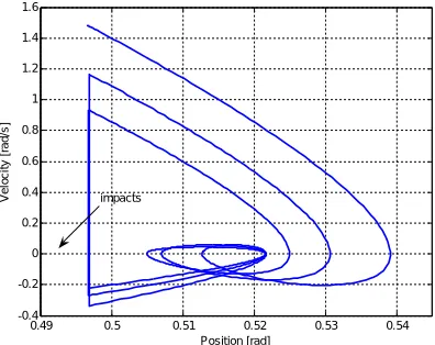
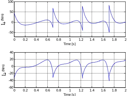
results given by figures 2 and 3 show the efficiency of our proposed method applied to the planar biped robot of figure 1. It can be clearly seen, from figures 2 and 3 that the proposed observer provides an excellent estimation of the robot position variables (stance leg and swing leg). In each figure, are shown both the real and estimated continuous position variables and the finite-time convergence of the position error estimation to zero. Figure 4 shows the finite time velocity estimation error of each link of the biped robot (the two legs and the torso). It can be seen from this figure that our observer provides a good estimation of the velocity variables in a finite time. Figures 5 and 6 display respectively the phase portrait of the stance leg and the swing leg of the biped robot. It can be clearly seen, from these figures, that the controller (18) ensures stable cycles. The control signals, provided by the proposed controller, are strongly based on the estimated variables and shown in figure 7.
0 0.5 1 1.5 2 2.5 3 3.5 4 4.5 -0.5
0 0.5 1
Time [s]
A
n
g
u
la
r
p
o
s
it
io
n
[
ra
d
]
Sta nce Leg of the biped robot
0 0.05 0.1 0.15 0.2 0.25 0.3 0.35 0.4 0.45 0.5 -0.3
-0.2 -0.1 0 0.1
Time [s]
P
o
s
it
io
n
e
s
ti
m
a
ti
o
n
e
rr
o
r
[r
a
d
]
Real Estimated
impacts
Fig. 2 Position variables of the stance leg of the biped robot : (a) Continuous position variables (real and estimated); (b) Finite-time convergence of the
position error estimation to zero.
0 0.5 1 1.5 2 2.5 3 3.5 4 4.5 -0.4
-0.2 0 0.2 0.4
Time [s]
a
n
g
u
la
r
P
o
s
it
io
n
[
ra
d
]
Swing leg of the biped robot
0 0.05 0.1 0.15 0.2 0.25 0.3 0.35 0.4 -0.05
0 0.05 0.1 0.15 0.2
Time [s]
P
o
s
it
io
n
e
s
ti
m
a
ti
o
n
e
rr
o
r
[r
a
d
]
real estimated
impacts
Fig.3 Position variables of the swing leg of the biped robot: (a) Continuous position variables (real and estimated); (b) Finite-time convergence of the
position error estimation to zero.
0 0.02 0.04 0.06 0.08 0.1 0.12 0.14 0.16 0.18 0.2 -0.4
-0.2 0
Velocity estimation errors of each link of the biped robot
0 0.02 0.04 0.06 0.08 0.1 0.12 0.14 0.16 0.18 0.2 0
0.2 0.4
E
rr
o
r
v
e
lo
c
it
y
e
s
ti
m
a
ti
o
n
e
rr
o
rs
[
ra
d
/s
]
0 0.02 0.04 0.06 0.08 0.1 0.12 0.14 0.16 0.18 0.2 0
0.5 1
Time [s]
Stance Leg
Swing Leg
Torso
Fig.4 Finite-time convergence of the velocity estimation error of each link of the biped robot: (a) stance leg; (b) swing leg; (c) Torso.
-0.4 -0.3 -0.2 -0.1 0 0.1 0.2 0.3 0.4 0.5 0.6 -2.5
-2 -1.5 -1 -0.5 0 0.5 1
position [rad]
v
e
lo
c
it
y
[
ra
d
/s
]
impacts
Fig. 5 Stable walking cycle : Phase portrait of the stance leg of the planar robot (angular position in radians versus velocity in radians/seconds)
0.49 0.5 0.51 0.52 0.53 0.54 -0.4
-0.2 0 0.2 0.4 0.6 0.8 1 1.2 1.4 1.6
Position [rad]
V
e
lo
c
it
y
[
ra
d
/s
]
impacts
ISSN: 2231-5381
http://www.ijettjournal.org
Page 1906
0 0.2 0.4 0.6 0.8 1 1.2 1.4 1.6 1.8 2-50 0 50 100
1
(
N
m
)
Time [s]
0 0.2 0.4 0.6 0.8 1 1.2 1.4 1.6 1.8 2 -60
-40 -20 0 20 40
2
(
N
m
)
Time [s]
Fig. 7 Applied torques based on estimated variables.
VI. CONCLUSIONS
In this paper, we have proposed a partial feedback linearization technique for controlling an under-actuated walking biped robot. After the formulation of the hybrid model of the system under consideration, we have shown that the vector of actuated configurations can be completely linearized and decoupled from the vector of non-actuated configurations. Then, since the velocity signals are not available, the control law was coupled with our proposed hybrid observer in order to estimate the velocity vector of the mechanical system. Simulation results applied to the three-link biped robot show that the control strategy, based on estimated variables, induces exponentially stable walking locomotion.
APPENDIX
Appendix1: Matrices details of the biped robot
This Appendix contains the definition of all matrices of the biped model for continuous motion part
Inertia Matrix : M(q)
33 32 31
23 22 21
13 12 11
)
(
m
m
m
m
m
m
m
m
m
q
M
where)
cos(
.
l
.
r
.
M
m
m
)
cos(
.
r
.
m
2
1
m
m
r
).
M
M
m
4
5
(
m
3 1 T
31 13
2 1 2
21 12
2 T H 11
2 22
m
.
r
4
1
m
2 T 33 32
23
m
0
,
m
M
.
l
m
Coriolis and centrifugal forces matrix: C
33 32 31
23 22 21
13 12 11
)
,
(
c
c
c
c
c
c
c
c
c
q
q
C
where1 3 1 T
31
3 3 1 T
13
1 2 1 2 21
2 2 1 2 12
32 23 33 22 11
).
sin(
.
l
.
r
.
M
c
).
sin(
.
l
.
r
.
M
c
).
sin(
.
r
.
m
2
1
c
).
sin(
.
r
.
m
2
1
c
0
c
c
c
c
c
Vector of gravitational forces : G(q)
31 21 11
)
(
g
g
g
q
G
where:
)
sin(
.
.
.
)
sin(
.
.
.
.
2
1
)
sin(
.
).
2
.
3
2
.(
.
2
1
3 31
2 21
1 11
l
M
g
g
r
m
g
g
r
M
m
M
g
g
T
T H
Matrix of the effects of actuators on the generalized coordinates B(q)
1
1
1
0
0
1
ISSN: 2231-5381
http://www.ijettjournal.org
Page 1907
Appendix2: Matrices corresponding to the impactmodel
ext e
e e
e
(
q
).(
q
q
)
F
M
where
2 T H
e
(
5
.
m
4
M
4
.
M
).
r
4
1
)
1
,
1
(
M
2
e
m
.
r
4
1
)
2
,
2
(
M
,)
cos(
r
.
m
2
1
)
1
,
2
(
M
)
2
,
1
(
M
e
e
2
1
2 ,0
)
2
,
3
(
M
)
3
,
2
(
M
e
e
)
cos(
.
l
.
r
.
M
)
1
,
3
(
M
)
3
,
1
(
M
e
e
T
1
3)
cos(
.
r
.
m
2
1
)
2
,
4
(
M
)
4
,
2
(
M
e
e
2 ,) cos( . r ). M 2 M 2 m . 3 ( 2 1 ) 1 , 4 ( M ) 4 , 1 (
Me e H T 1
) sin( . r ). M 2 M 2 m . 3 ( 2 1 ) 1 , 5 ( M ) 5 , 1 (
Me e H T 1
)
sin(
.
r
.
m
2
1
)
2
,
5
(
M
)
5
,
2
(
M
e
e
2 ,2 T e
(
3
,
3
)
M
.
l
M
,)
cos(
.
l
.
M
)
3
,
4
(
M
)
4
,
3
(
M
e
e
T
3 ,)
sin(
.
l
.
M
)
3
,
5
(
M
)
5
,
3
(
M
e
e
T
3 ,0
)
4
,
5
(
M
)
5
,
4
(
M
e
e
,T H e
e
(
4
,
4
)
M
(
5
,
5
)
2
m
M
M
M
Appendix3: partitioned matrices used in control law
This Appendix contains the partitioned matrices of the biped model utilized for the development of the feedback controller
2 2
1 2
2 1 2 2
T H 22
3 1 T
21
3 1 T
12
2 T 11
r . m 4 1 )
cos( . r . m 2 1
) cos( . r . m 2 1 r ). M M m 4 5 ( M
0
) cos( . l . r . M M
0 ) cos( . l . r . M M
l . M M
REFERENCES
[1] M. W. Spong, “Energy based control of a class of underactuated mechanical systems", in IFAC World Congress, July 1996.
[2] M. W. Spong and L. Praly, “Control of underactuated mechanical systems using switching and saturation", in Proc. of the Block Island Workshop on Control Using Logic Based switching, 1996.
[3] C.-Y. Su and Y. Stepanenko, “Sliding mode control of nonholonomic systems: Underactuated manipulator case", in Proc. IFAC Nonlinear Control Systems Design, Tahoe City, CA, 1995, pp. 609-613. [4] H. K. Khalil, Nonlinear System,. Prentice-Hall, Inc., 1996.
[5] N. Faiz, S. K. Agrawal, and R. M. Murray, “Trajectory planning of differentially flat systems with dynamics and inequalities,” AIAA J. Guid. Contro, Dyn., vol. 24, no. 2, pp. 219–227, 2001.
[6] H. Sira Ramirez and S. K. Agrawal, Differentially Flat Systems. New York/Basel, Switzerland: Marcel Dekker, 2004.
[7] M.W. Spong, “The control of underactuated mechanical system”, In
International conference on Mechatronics, Mexico city, 1994. [8] Xian B., M.S. Queiroz, D. M. Dawson, M. L. McIntyre, “A
discontinuous output feedback controller and velocity observer for nonlinear mechanical systems”, Automatica, vol. 40, pp 695-700, 2004. [9] Juan Resendiz, Wen Yu, Leonid Fridman, Two-Stage Neural Observer for Mechanical Systems, IEEE transactions on circuits and systems, vol. 55, pp. 1076-1080, 2008.
[10] Canudas De Wit, J.J.E. Slotine, “Sliding observers for robot manipulators”, Automatica, vol. 27, pp. 859-864, 1991.
[11] L. Menini and A. Tornambè, “Velocity observers for linear mechanical systems subject to single non-smooth impacts”, Systems and Control Letters, vol. 43, pp. 193-202, 2001.
[12] Davila, J., Alessandro Pisano and Elio Usai, “Continuous and discrete state reconstruction for nonlinear switched systems via high-order sliding-mode observers”, International Journal of Systems Science, vol. 1-11, 2010.
[13] Davila, J., Leonid Fridman, and Arie Levant, “Second-Order Sliding-Mode Observer for Mechanical Systems”, IEEE Transactions on Automatic Control, vol. 50-11, 2005.
[14] Lebastard V., Y. Aoustin, and F. Plestan, “Second order sliding mode observer for stable control of a walking biped robot”, in Proceeding IFACWorld Congress, Praha, Czech Republic, 2005.
[15] Saadaoui, H., Manamanni, N., Djemai, M., Barbot, J.P., and Floquet, T, “Exact Differentiation and Sliding Mode Observers for Switched Lagrangian Systems”, Nonlinear Analysis, vol. 65, pp. 1050–1069, 2006.
[16] V. Lebastard, Y. Aoustin, and F. Plestan, “Observer-based control of a biped robot,” in Proc. Fourth International Workshop on Robot Motion and Control, Puszczykowo, Poland, 2004, pp. 67–72.
[17] Mchiri Mohamed, Trabelsi Karim and Belghith Safya. “Sliding mode observer for nonlinear mechanical systems subject to nonsmooth impacts”, in 7th IEEE International Multi-Conference on Systems,