http://www.sciencepublishinggroup.com/j/ijtet doi: 10.11648/j.ijtet.20190503.11
ISSN: 2575-1743 (Print); ISSN: 2575-1751 (Online)
Ship Hull Form Optimization: A Computational Fluid
Dynamics (CFD) Approach
Donatus Eberechukwu Onwuegbuchunam
1, Favour Chimobi Ogbenna
1,
Nnaemeka Charles Ezeanya
2, Kenneth Okechukwu Okeke
11
Department of Maritime Management Technology, Federal University of Technology, Owerri, Nigeria 2
Department of Agricultural & Bio-Resources Engineering, Federal University of Technology, Owerri, Nigeria
Email address:
To cite this article:
Donatus Eberechukwu Onwuegbuchunam, Favour Chimobi Ogbenna, Nnaemeka Charles Ezeanya, Kenneth Okechukwu Okeke. Ship Hull Form Optimization: A Computational Fluid Dynamics (CFD) Approach. International Journal of Transportation Engineering and Technology. Vol. 5, No. 3, 2019, pp. 43-49. doi: 10.11648/j.ijtet.20190503.11
Received: June 17, 2019; Accepted: August 14, 2019; Published: October 15, 2019
Abstract:
Performance of ship resistance and other propulsion characteristics greatly depend on ships’ hull form. However, design considerations based on range of hull modifications can be practically limited by material and time resources, hence the need for computational optimization techniques based on Computational Fluid Dynamics (CFD). In this paper, hull form of a parent vessel: single screw supply vessel was screen designed and then sequentially optimized for total resistance and wave height through the application of CFD technique. The modelling was done using ANSYS®, CAESES® and NAVCAD® workbench. Input parameters included moulded beam, steepness of stem and length overall. These were the basis for parametric variations of hull forms during optimization. The optimization processes (based on turbulent flows) lasted for about two hours. A model of the optimized hull was built and tested in marine towing tank with appendages including propeller and rudder at respective model speeds in standard conditions. Towing tests showed that the optimized ship hull exhibited low resistance and decreased wave height in comparison with parent hull. The robustness of CFD technique particularly for stern to stem hull modification was further established.Keywords:
Hull Form Optimization, Computational Fluid Dynamics, Total Resistance, Wave Height, Navier Stokes Equation1. Introduction
An inherent problem in ship design is the alteration of ship hull forms (after she has been built) to suit the required criteria. Optimization by actual testing of ship hull models entails producing many model hull forms, building the corresponding models and testing them. This approach to optimization is resource consuming- takes great time and money. It is not ideal as it can only bring about a better but not best (optimal) hull form. Numeric computations involve use of software (s) to compute values of functions such as hull resistance and speed for given hull forms. This approach does not also provide an optimal solution but can improve on the existing one. It is relatively economical and involves use of many perturbation surfaces after which the improved hull form may be validated by building and testing the model.
However, optimization by automatic computation using Computational Fluid Dynamics (CFD) solvers and mathematical algorithms to automatically optimize hull forms are now employed by ship designers. We apply these techniques to improve the performance characteristics of a parent ship-a single screw service vessel initially built by DAMEN shipyard. The overall goal of this research was to optimize initial model of ship’s hull with respect to resistance and wave height using CFD technique.
Research Objectives
The specific objectives of research include:
1. To optimize performance of a service vessel based on objective function parameter of hull resistance using CFD technique.
2. To build a model of optimized hull based on the parent vessel.
This research was limited to investigation of ship hydrodynamic performances in hull form optimization. Attempt was made to find a ship hull form which hydrodynamic performance was optimal in terms of friction resistance and wave height.
2. Conceptual Framework
Computational Fluid Dynamics technique is a part of fluid mechanics which generates solutions and computations to fluid flows by numerical analyses and data structure. It presents mathematical models which aid simulations and has many applications which include: bio-medical, automotive, aerospace and general engineering. CFD can be used to analyze flows involving- gas-gas, liquid-gas, gas-solid and liquid-solid. It can analyze both internal and external flows. CFD can also be used to analyze flows around hull of a vessel. It basically solves for quantities such as velocity, pressure, temperature at discrete points in time and space. CFD software requires information about size, content and layout of data structure. It uses this information to create a 3D mathematical model on a grid that can be rotated and viewed from different angles. Solutions to fluid flows can be achieved using Navier Stokes equations in conjunction with continuity and energy equations (the flow equations). This equation emerges from theories such as conservation of mass, momentum and energy respectively and presents numerical models for different flow types- turbulent and laminar flows [1]. The Navier stokes equation is a basic equation in CFD. It presents a framework for which fluid flows could be analyzed. In the context of ship flows, the Navier stokes equation is presented in equation (1) to (4). Laminar flow is flow in which stream lines are highly ordered while turbulent flow involves flows which are random in terms of stream lines.
The continuity equation
( ) ( ) ( )
u v w 0x y z
∂ ∂ ∂
+ + =
∂ ∂ ∂ (1)
Navier Stokes equation
2 2 2
2 2 2
u u u p
u u u u
u v w
x y z x x y z
t µ ρ∂ + ∂ ∂ ∂ = −∂ ∂ ∂ ∂ ∂ + + + + + ∂ ∂ ∂ ∂ ∂ ∂ ∂
(2)
2 2 2
2 2 2
u u u p
u v v v
u v w
x y z y x y z
t µ ρ∂ + ∂ ∂ ∂ = −∂ ∂ ∂ ∂ ∂ + + + + + ∂ ∂ ∂ ∂ ∂ ∂ ∂
(3)
2 2 2
2 2 2
z u u u p z z z
u v w
t x y z z x y z
ρ∂ + ∂ + ∂ + ∂ ∂ +µ∂ +∂ +∂
∂ ∂ ∂ ∂ ∂ ∂ ∂ ∂
=− (4)
Where;
u, v, w, are component of velocity in the x, y, z direction respectively.
= density. = pressure.
µ= viscosity.
, , = body force in the x, y and z direction respectively.
Extant literature contains successful application of CFD techniques and various optimization algorithms for computational efficiency. Notable examples include: Szelangiewicz & Abramowski [2], who were more concerned with reducing optimization time in ship hull modelling. They employed improved particle swarm optimization algorithm (IPSO), an improvement on commonly applied PSO. IPSO algorithm was blended with Elman neural network to ensure prediction accuracy of total resistance. This method is also consistent with Zhang, B-Zhang, Tezdogan, Xu & Lai [3]. Zonga, Hong, Wang & Hefazi [4] applied ship hull modification method based on self-blending. The method enables the cross sections of the hull to be merged together instead of the whole ship hull. It shares the advantage of small number of design variables and has bigger optimization space. A RS (response surface) has been built to reduce the computation expense of optimization. Aksenov, Pechenyuk & Vučinić [5] applied CFD to improve hull form design through systematic variation of longitudinal distribution of the hull volume, while controlling the vertical volume distribution. Park, Choi & Chun [6], applied sequential quadratic programming algorithm. Their design separated the bow and stern, stating that flow around the bow is more non-viscous while the flow around the stern is dominantly viscous. Their objective functions for the optimization were: minimum wave-making resistance coefficient for the bow and minimum viscous pressure resistance coefficient for the stern.
Pérez & Clemente [7] proposed use of constrained methodology to reduce trial and error procedures associated with in hull form optimization. Kostasa, Ginnisb, Politisa & Kaklisc [8] focused on developing an appropriate ship-hull hydrodynamic optimization process, combining modern optimization techniques, a fully parametric T-spline ship-hull model and a BEM hydrodynamic solver for the calculation of ship wave resistance. Sar-oz [9] combined single and multi-objective to derive optimized hull forms to improve different aspects of sea keeping performance of designed vessel. Similar approach includes Vernengo, Brizzolara, Bruzzone [10]. Luo & Lan [11] applied parametric modelling to the hull design by using non-uniform rational basis spline (NURBS). Rankine-source panel method was used to calculate the wave-making resistance. A hybrid optimization strategy was applied to achieve the optimization goal. This approach is also similar to Wen, Mariyam, Shamsuddin & Samian [12]. Other examples include: Brizzolara, Vernengo, Pasquinucci & Harries [13], Ang, Goh & Li [14] and Wang [15].
The application of optimization technique incorporating parametric hull form variation using CFD is vital in optimization modelling. Hull form CFD based optimization comprises three processes which according to Park, Choi & Chun [6] include:
1.Initial hull form variation,
varied hull form, and,
3.The selection of the optimized hull form.
3. Material and Methods
3.1. Design Considerations
The following considerations were made during the design process:
i. The turbulence nature of the sea and how this nature affects the fluid flows around forward and aft of the vessel.
ii. The number of variables in optimization. These were variables subjected to changes in the course of optimization. These variables are LOA/LWL, beam and the gradient of curve advancing towards the stem from the amid-ship.
iii.The degree of change allowed in the variables. Only small changes were allowed in the variables. The limits of changes ∆ allowed are as shown in table 1.
Table 1. Degree of Changes Allowable in Optimization Variables.
Variable Lower limit Actual value Upper limit
LWL 50 54 56
Beam 9.6 10.2 10.3
Entrance 185 190 195
Source: CAESES friendship system version 4.3.
3.2. Material Selection
The following softwares for were employed for the hull form optimization; viz:
i. CAESES® friendship system.
ii. Analysis system; ANSYS® is a work bench integrated with CFD software for solving the Navier strokes and Reynolds averaged Navier stokes equations.
iii.NAVCAD® integrated with CAESES® process predicted and analyzed the total resistance, power, torque etc. of the ship hull.
The shape variation system of CAESES® software permitted enhancement of variations of initial design with respect to the range of changes allowed in specified parameters, and allowing for visualization of designs when design parameters were altered. Strawboard, a carton-like material was used for developing the prototype of optimized hull form. Other materials used included:
i. Enamel spray paint. ii. Oil paint.
iii. Markers. iv. Hardener. v. Aluminum sheet. vi. Rotor.
vii. Masking tape. viii.Cutters.
The parent ship based design method was adopted for this research. A single screw service craft originally designed by DAMEN Shipyard Inc. Nigeria was re-modeled using CAESES® friendship system after which variations in design
in the system was initiated. Thereafter, computational fluid dynamics (CFD) based numerical simulation and optimization was performed using the ANSYS® system workbench. NAVCAD® was subsequently employed to analyze the initial and optimized hull which was validated after the model of the optimized hull was built. The processes involved were explained under the following headings:
i. Model development, ii. Variation of design,
iii.Optimization using ANSYS®, iv.NAVCAD® analysis and,
v. Development of prototype/validation.
3.3. Model Development
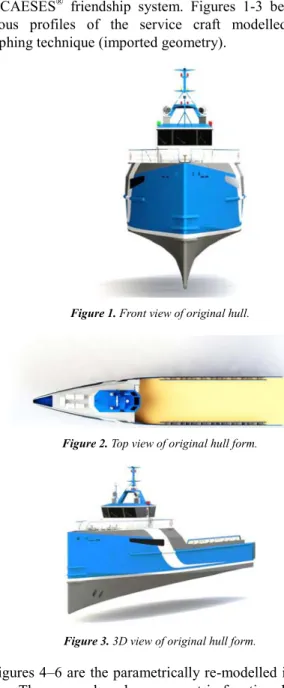
In the course of initial hull form development, an existing single screw service craft modeled in 3D was re-modeled to an approximated dimension of the Damen’s ship hull using the CAESES® friendship system. Figures 1-3 below show various profiles of the service craft modelled through morphing technique (imported geometry).
Figure 1. Front view of original hull.
Figure 2. Top view of original hull form.
Figure 3. 3D view of original hull form.
Figure 4. 3D view of initial hull-form.
Figure 5. Port-side of initial hull-form.
Figure 6. Top-view of initial hull-form.
Figure 7. Parametric functions.
Table 2 presents characteristics of the ship modelled for optimization.
Table 2. Characteristics of the service craft.
Characteristics Value
LOA (m) 53
LWL (m) 54
Characteristics Value
Draft (m) 4.4
Beam (m) 10.2
Bow-type Axe Bow
Volume under water (m3) 489.21
Center of buoyancy (m) 30.621, 0, -0.81019
Center of floatation (m) 23.4740 from FWD
Water plane area 469.2m2
Source: CAESES® friendship system version 4.3.
3.4. Variation of Designs
After the hull model was developed with appropriate design variables, this initial design was varied. The variation was performed based on three parameters (or three design variables) which were limited to small changes. To reduce the computational time, the number of variation was limited to twenty.
Source: CAESES® friendship system version 4.3.
Figure 8. Variation of initial hull in CAESES System.
3.5. Optimization Using ANSYS®
Prior to the actual computation, the hull form was meshed, see figure 9. The whole hull (stem to stern) was optimized at the same time based on turbulent fluid flow. The finite volume method was used for discretization. Further analysis on the flows was performed using NAVCAD® to predict the resistance of optimized hull at 25knots.
3.6. Development of Prototype/Validation
Source: CAESES® friendship system version 4.3.
Figure 9. Model shows meshing of the hull.
(Source: researcher).
Figure 10. Laying of keel.
Source: researcher.
Figure 11. Model after the main hull was fixed, ready for laying of upper deck forward and aft.
Source: researcher.
Figure 12. Model after painting was done.
Source: researcher.
Figure 13. Model ready for sea trials.
4. Presentation and Discussion of Results
4.1. Comparison of Wave Height of Optimized and Initial Hull
Source: researcher.
Figure 14. Speed Vs Wave height.
indicates that as speed increases, the difference between the maximum height of optimized hull form and initial hull form increases, with that of the new hull form always lower than the initial one.
Table 3. Initial and optimized hull wave height at specified speed ranges.
Speed (knots) Initial h Optimized h
10 0.10 0.10
12 0.15 0.14
14 0.19 0.18
16 0.53 0.53
18 1.25 1.24
Speed (knots) Initial h Optimized h
20 1.40 1.29
22 1.92 1.90
24 2.50 2.35
30 2.70 2.60
Source: CAESES® friendship system version 4.4.
Improvements in parameters of optimized hull form compared with initial (baseline) model are shown in table 4. The actually hull form models defined by these parameters can also be observed in figure 15.
Table 4. Data on initial and optimized hull.
Characteristics Initial hull Optimized hull
LOA (m) 54 53.87
Lpp (m) 54 53.87
Draft (m) 4.4 4.40
Beam (m) 10.2 9.70
Bow-type Axe bow Axe bow
Volume under water (m3) 489.21 457.096
Center of buoyancy (m) 30.623, 0, -0.81019 30.1062, 0, -0.803789
Center of floatation (m) 23.4740 from FWD 23.0656 from FWD
Water plane area (m2) 469.2m2 444.253m2
Tangent 190 194.6
Source: CAESES® friendship system version 4.4.
Figure 15. Comparison of Initial Hull (1st) and Optimized Hull (2nd).
4.2. Comparison of Total Resistance of Optimized and Initial Hull
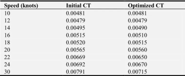
Table 5 presents data on total friction resistance against speed. The outputs were obtained from comparative analysis on initial and optimized hull forms performed using NAVCAD®. From figure 16 (graph of total resistance against speed), it can be deduced that the optimized hull has lesser total resistance than the initial one at speed ranges.
Table 5. Total resistance and speed.
Speed (knots) Initial CT Optimized CT
10 0.00481 0.00481
12 0.00479 0.00479
14 0.00495 0.00490
16 0.00515 0.00510
18 0.00520 0.00515
20 0.00565 0.00560
22 0.00669 0.00650
24 0.00692 0.00670
30 0.00791 0.00715
Source: NAVCAD® version 9.1.
Source: Researcher.
Figure 16. Speed Vs total resistance.
4.3. Validation: Model Testing
After optimization, the model of optimized hull was built with superstructure and propeller appendage. She was built to scale 1:100 and was tested in marine towing tank. The model craft sailed at a speed equivalent to 25knots of full scaled vessel. She exhibited better wave and resistance characteristics than the initial model.
5. Conclusion and Recommendation
and wave height. Geometry of the parent ship was imported into the CAESES system using the morphing function. The resulting hull model was subsequently optimized using the integrated software system with CFD optimization capabilities. For performance analysis, friction resistance for optimized and parent hull forms were compared using the NAVCAD software. Thereafter, prototype of the optimized hull was built with appendages attached and towing tests carried out. The tests showed that the prototype model exhibited reduced resistance and wave height. Thus, propulsion characteristics improvement (reduced resistance and wave height) can lead to increased speed beyond that required for a vessel and hence result in cost savings.
This study demonstrates that the objective optimization tool based on CFD technique can and should be employed in the simulation based design of hull forms for reduced drag in order to save time and other valuable resources. It is also recommended that:
Hull form which longest beam is at the aft should be optimized at a time as this saves time than carrying out computations for stern and stem differently. Sufficient time should be spent in understanding the hull form and the nature of flows it exhibits.
References
[1] Wendt, J. F (2009), Computational Fluid Dynamics: An introduction. Springer-Verlag Berlin Heidelberg, Germany.
[2] Szelangiewicz, T & Abramowski, T. (2009) Numerical analysis of influence of ship hull form modification on ship resistance and propulsion characteristics. Polish Maritime Research 4 (62) Vol. 16; Pp. 3-8.
[3] Zhang, S, Zhang, B, Tezdogan, T, Xu L & Lai, Y (2018) Computational fluid dynamics-based hull form optimization using approximation method, Engineering Applications of Computational Fluid Mechanics, 12: 1, 74-88, DOI: 10.1080/19942060.2017.1343751.
[4] Zonga, Z, Hong, Z, Wang, Y, & Hefazi, H (2018), Hull form optimization of trimaran using self-blending method, Applied Ocean Research, Vol. 80, 240-247.
[5] Aksenov, A. A, Pechenyuk, A. V & Vučinić, D (2015). Ship
hull form design and optimization based on CFD. Towards Green Marine Technology and Transport – Guedes Soares, Dejhalla & Pavleti (Eds) © 2015 Taylor & Francis Group, London, ISBN 978-1-138-02887-6.
[6] Park, J. H, Choi, J. & Chun, H. (2015) Hull-form optimization of KSUEZMAX to enhance resistance performance. International Journal of Naval Architecture & Ocean Engineering, Vol. 7, 100-114.
[7] Pérez, F, Clemente, J. A. (2011), Constrained design of simple ship hulls with B-spline surfaces Computer-Aided Design 43, 1829-1840.
[8] Kostasa, K. V, Ginnisb, A. I, Politisa, C. G & Kaklisc, P. D (2015), Ship-hull shape optimization with a T-spline based BEM–isogeometric solver Comput. Methods Appl. Mech. Engrg. 284, 611-622.
[9] Sar-oz, E (2009) Inverse design of ship hull forms for seakeeping. Ocean Engineering 36, 1386-1395.
[10] Vernengo, G.; Brizzolara, S.; Bruzzone, D. (2015), Resistance and seakeeping optimization of a fast multihull passenger ferry. Int. J. Offshore Polar Eng. 25, 26-34.
[11] Luo, W & Lan, L (2017), Design Optimization of the Lines of the Bulbous Bow of a Hull Based on Parametric Modeling and Computational Fluid Dynamics Calculation Mathematical and Computer Application, 22, 4; doi: 10.3390/mca22010004.
[12] Wen, A. S.; Mariyam, S.; Shamsuddin, H. & Samian, Y. (2006), Optimized NURBS ship hull fitting using simulated annealing. In Proceedings of the International Conference on Computer Graphics, Imaging and Visualisation, Sydney, Australia, 26-28 July 2006; pp. 484–489.
[13] Brizzolara, S.; Vernengo, G.; Pasquinucci, C. A.; Harries, S. (2015), Significance of parametric hull form definition on hydrodynamic performance optimization. In Proceedings of the MARINE 2015-Computational Methods in Marine Engineering VI, Rome, Italy, 15-17; pp. 254-265.
[14] Ang, J.; Goh, C.; Li, Y. (2015), Hull form design optimization for improved efficiency and hydrodynamic performance of “ship-shaped” offshore vessels. In Proceedings of the International Conference on Computer Applications in Shipbuilding, Bremen, Germany, 29 September-1 October 2015; pp. 1-10.