Second minimum approximation for Min-Sum
decoders suitable for high-rate LDPC codes
J.M. Catal`a-P´erez J.O. Lacruz
F. Garc´ıa-Herrero J. Valls
David Declercq
Abstract
In this paper a method to approximate the second-minimum required in the computation of the
check node update of an LDPC decoder based on Min-sum algorithm is presented. The proposed
approximation compensates the performance degradation caused by the utilization of a first-minimum
and pseudo second-minimum finder instead of a true two-minimum finder in the Min-sum algorithm
and improves the BER performance of high-rate LDPC codes in the error floor region. This approach
applied to a complete decoder reduces the critical path and the area with independence of the selected
architecture. Therefore, this method increases the maximum throughput achieved by the decoder and its
area-throughput efficiency. The increase of efficiency is proportional to the degree of the check node,
so the higher the code rate is, the higher the improvement in area and speed is.
Index Terms
LDPC codes, decoding, min-sum, two minimum finder, high speed architecture
This research was supported by the Spanish Ministerio de Ciencia e Innovaci´on and FEDER, under Grant No.
TEC2015-70858-C2-2-R and partially funded by the Institut Universitaire de France.
J.M. Catal`a-P´erez and J. Valls are with the Instituto de Telecomunicaciones y Aplicaciones Multimedia, at Universitat
Polit`ecnica de Val`encia, 46730 Gandia, Spain (e-mail: [email protected], [email protected]
J.O. Lacruz is with IMDEA Networks Institute, Madrid, 28918, Spain. (e-mail: [email protected])
F. Garc´ıa Herrero is with ARIES Research Center, Universidad Antonio de Nebrija, C/ Pirineos, 55 E-28040 Madrid,
Spain. (e-mail: [email protected])
D. Declercq is with ETIS Laboratory, ENSEA/Univ. Cergy-Pontoise/CNRS-UMR-8051, 6, Avenue du Ponceau, F-95000,
I. INTRODUCTION
The complexity of the check node update equations of a low-density parity-check (LDPC)
[1] decoding algorithm usually limits the whole efficiency of the derived hardware architectures.
Due to this fact, several proposals have been presented in literature since the first decoding
algorithm, sum-product [2], was introduced. Among the low-complexity decoding algorithms,
the Min-Sum algorithm (MSA) [3] is probably the most practicable solution, since it provides
a good trade-off between coding gain and complexity.
The check node update equation of MSA comprises the search of the two lowest values (first
and second minimum) among the dc input messages. The magnitude of the output messages
of dc−1 check nodes is the absolute minimum of the dc input messages (the first minimum). Only for the output message of the node that sends the least reliable message, its magnitude
is the second least reliable magnitude within the dc input messages (the second minimum).
Not using a second minimum introduces some important performance degradation in the
error-floor region. Although there are very efficient designs of two-minimum finders [4], [5], the
fact of searching the second minimum always implies an area overhead and a reduction of the
maximum throughput, compared to the search of only one minimum. To further improve the
implementations of MSA decoders, several methods to approximate the second minimum at the
check node have been recently proposed.
The first one is the single-minimum Min-sum from [6], [7], in which the second minimum is
estimated applying a constant correction factor on the first minimum. This technique has very
low complexity, but unfortunately, it introduces a non-negligible performance degradation near
the error floor region, especially for high-rate LDPC codes. This happens because the distance
between the absolute minimum and the second minimum is not constant through the iterations
or through different signal-to-noise (SNR) ratio values.
To overcome this problem a variable-weight Min-sum algorithm (vwMSA) was proposed in
[8]. The vwMSA avoids performance degradation by means of computing a different correction
factor for each iteration or range of iterations. This algorithm requires an optimization of
parameters that depends on the number of iteration, the value of the correction factor in the
previous iterations and the SNR. In addition, to find the best combination of parameters for each
case could take too much time as there is a recursive relation between the values of different
storage of several scaling values and the definition of a range of iterations that changes with each
different LDPC code. However, this algorithm, due to a slowdown of its convergence, improves
the BER performance of the MSA for large SNR, as it delays the appearance of the error floor.
Another low cost approximation for the second minimum, called Normalized Probabilistic
Min-Sum algorithm (NPMSA), was proposed in [9]. It uses a single-minimum tree in which
the discarded value in the last stage of the tree is taken as the probabilistic second minimum.
Both, the first and the second minimum, are scaled by a normalization factor to improve the
performance. The same approach was utilized in [10], however, instead of a normalization, a
subtractive correction factor is added to the second minimum to enhance the performance. Both
approaches work very well in the waterfall of the BER performance curve, however, they do not
work well for large SNR values, exhibiting an early error floor.
In this paper, inspired by our approximation for non-binary LDPC codes over GF(q) [11],
a method to approximate the second minimum required by the check node in binary LDPC
decoders is proposed. This estimation combines the simplicity of [9], [10], because it uses the
discarded value in a single-minimum tree as probable second minimum, with the adaptability of
[8], as far as the proposed method does not use the same correction factor in different iterations.
Moreover, this approximation does not require a thorough off-line optimization, because with
only two constant factors per code the second minimum is estimated dynamically. Our second
minimum approximation for the Min-Sum algorithm introduces negligible performance loss (less
than 0.1dB) for high-rate codes and good performance for high SNR values and allows a faster
optimization of the parameters.
The rest of the paper is structured as follows: Section II makes a brief summary of the basic
of LDPC code’s decoding; Section III describes the proposed second minimum approximation
for the Min-Sum algorithm; Section IV shows the hardware results of a Min-sum decoder that
uses the novel approach and performs comparisons with the existing solutions from literature;
and finally, in Section V conclusions are outlined.
II. BASIS OF LDPC CODE’S DECODING
LetH be the M×N parity check matrix with entries hi,j that defines an (N,K) LDPC code.
cardinalities of the setsNi andMj are the degree of check-node (dc) and the one of variable-node (dv).
The codeword c= (c0, c1, ..., cN−1), which satisfies the equation c·HT =0, is modulated in
binary phase-shift keying (BPSK) and transmitted over an additive white Gaussian noise (AWGN)
channel. The received sequence is denoted by y = (y0, y1, ..., yN−1), with y = c+e, with
e= (e0, e1, ..., eN−1)being the vector representation of the Gaussian-distributed error introduced
by the channel. The log-likelihood ratio (LLR) can be computed asL = (L0, L1, ..., LN−1)where
Lj =−2·yj/σ2, (1)
with j ∈(0,1, ..., N −1), and σ is the standard deviation of the noise in the channel.
For the Min-sum decoding algorithm the variable nodes (Ri,j) are initialized as Ri,j = Lj
with j ∈ {0, . . . , N−1}, i∈ Mj. After this, each check node processes dc incoming messages, from dc connected variable nodes. To compute the reliability of the results obtained from the
parity check equation the check node messages, σi,j, are calculated as
σi,j = min j0∈N
i\j
(|Ri,j0|)×
Y
j0∈N
i\j
sign(Ri,j0). (2)
Then, variable nodes are updated using the new σi,j messages following this equation:
Ri,j =Lj+α· Σ i0∈M
j\i
σi0,j, (3)
where α is a scaling factor that improves the error correction performance. Check node and
variable node update equations are computed again, taking advantage of the new information,
until a maximum number of iterations is reached or all the parity check equations are satisfied.
The estimated codeword is obtained by means of
˜
cj =sign(Lj +α· Σ i0∈M
j
σi0,j). (4)
The most complex operation of this algorithm from a hardware point of view is the check
node update, especially to process the magnitude of the messages: min
j0∈N
i\j
(|Ri,j0|). If j∗ is the
index of the minimum magnitude among the dc incoming messages, the magnitude for the
output messages with indexes different from j∗ is the absolute minimum min
j0∈N
i
(|Ri,j0|) and for
the index j∗ is the second minimum defined as min
j0∈N
i\j∗
(|Ri,j0|). Due to this fact, the derived
hardware architecture requires a dc-input two-minimum finder processor, which in its parallel
tree processor and has higher critical path (it adds an extra delay of(dlog2(dc)e−1)tmux)[4]. For this reason, we propose an approximation in next subsection to compute the second minimum
without increasing hardware too much or sacrificing error correction performance.
III. SECOND MINIMUM APPROXIMATION
Let us define the sets N0i and N1i as N0i∪ N1i = Ni, where the cardinality of N0i and
N1i is #N0i = #N1i =dc/2. The absolute minimum (min1) defined using the previous sets
is min( min
j0∈N0
i
(|Ri,j0|), min
j0∈N1
i
(|Ri,j0|)). From the previous equation the complementary operation,
max( min
j0∈N0
i
(|Ri,j0|), min
j0∈N1
i
(|Ri,j0|)), will satisfy1 that in a 50% of the cases is equal to the second
minimum (min2), (min1 ∈ N0i∧min2 ∈ N1i)∨(min1 ∈ N1i∧min2 ∈ N0i), and in the rest the value is larger, (min1, min2 ∈ N0i)∨(min1, min2 ∈ N1i). This set definition is related with the architecture of a one minimum tree finder where the sets N0i and N1i represent the elements of each half of the tree. In the last stage of the tree the value that is not selected as
minimum by the multiplexer is the result ofmax( min
j0∈N0
i
(|Ri,j0|), min
j0∈N1
i
(|Ri,j0|)), which we named
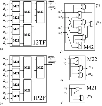
as min0002 and it is a rough approximation of the second minimum. The hardware architecture of this finder of the first minimum and a pseudo second minimum (1P2F) is shown in Fig. 1b.
From the hardware point of view, the use of this kind of finder instead of the true two-minimum
finder (Fig. 1a) has clear advantages: it requires nearly the half of resources and its critical path
is reduced in dlog2(dc)e −1 multiplexors, as shown in Table I.
The 1P2F finder of Fig. 1b was already used to estimate the second minimum in NPMSA [9].
Their authors implemented a normalized MSA scaling both the true first minimum value and the
estimated (probabilistic) value by an α coefficient, as shown in Fig. 2a. On the other hand, in
[10] the 1P2F finder was also utilized in their rExMin-n algorithm. As the authors realized that
the probabilistic second minimum is always greater than or equal to the true second minimum
value, to improve the performance of the normalized MS, besides scaling by a factor α the first
minimum, they added a reduction factorr to themin0002 and some control logic to avoid that the reduction factor decrements the value of the second minimum below the true value of the first
minimum. Its hardware structure is shown in Fig. 2b. Both approaches [9], [10] exhibit good
performance, very close to the normalized MS algorithm (NMSA), in the waterfall of the BER
curve. However, their performance is deteriorated for large SNR values, where the BER is very
1
R
M22
R
R
R
R
R
R
R
v1
v2
0 1M22
M22
M22
M42
M42
M42
min
min
0 1v1
v2
0 1 i,0 i,1 i,2 i,3 i,4 i,5 i,6 i,7R
R
R
R
R
R
R
R
i,0 i,1 i,2 i,3 i,4 i,5 i,6 i,712TF
1P2F
M42
M22
M21
'''
M21
M21
M21
M21
M21
M21
M22
m1
m2
m1
m2
0 0 1 1a)
b)
c)
d)
e)
>
>
>
>
>
1
2
m
1
m
2
m
2
m
1
m
1
min
min
1
2
Fig. 1. a) True two-minimum tree finder withdc = 8; b) true first-minimum and pseudo second-minimum tree finder with
dc= 8; c) module to find the true two minimum of a pair ofmin1 andmin2 values; d) module to find themin1 and min2
of two values; and e) module to findmin1of two values.
low, where an early error floor appears. This performance degradation is due to the fact that
their second minimum estimators do not take into account that the distance between messages
varies depending on the number of iterations and the SNR value.
In order to overcome this problem our estimator compensates min0002, considered as an upper bound (overestimation) ofmin2, withmin1, which is used as a lower bound. The min1 value is
r
+
2
+
a)
b)
c)
min
1min
1min
1min
2*min
2*min
2*…
min
1R
i,0R
i,dc-1min
2’’’
…
min
1R
i,0R
i,dc-1min
2’’’
…
min
1R
i,0R
i,dc-1min
2’’’
1P2F
1P2F
1P2F
>
Fig. 2. Second minimum estimators based on 12TF: a) Probabilistic second minimum from [9], b) rExMin-n from [10] and c)
proposed second minimum estimator.
we obtain min∗2 = min1 ·α2 +min0002 ·γ (Fig. 2c), which is similar to an average of the two
bound values (i.e. min1 and min0002).
Both α2 and γ allow us to weight each one of the approximations depending on the code. It
is important to remark that min∗2 auto-adjusts the correction value applied to min1 by a factor
α=α2+
min0002 min1
·γ, because the estimation includes a reference of the magnitude of the rest of the messages. The optimization ofα2 and γ is done by simulations of only one SNR ratio (with
BER=10−8). First, we fix the value of γ to 0.5 and find the optimum value of α
2, the one that
gives a performance as close as possible to the waterfall slope of the MSA; then, we fix α2
to its optimum value, and we perform the optimization of the γ parameter. The values of the
parameters are limited to hardware friendly values. In terms of hardware, the multiplications by
α2 and γ are implemented with only one adder, as the factors are selected as 2−x or 1−2−x,
TABLE I
COMPARISON FOR 12TF AND 1P2F FINDERS
Finder Comp. Mux. Critical path
12TF 2dc−3 3dc−4 dlog2(dc)e(tcmp+ 2tmux)−tmux
1P2F dc−1 dc dlog2(dc)e(tcmp+tmux)
A. Error correction performance
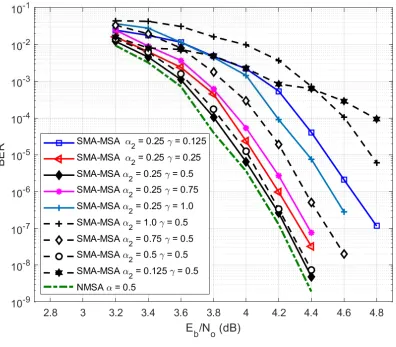
To demonstrate that min∗2 is an accurate approximation, we performed several simulations in both waterfall and error floor regions over different codes using the FPGA-based emulator from
[12] and a C++ model. Fig.3 shows the BER performance of the (2048,1723) LDPC code for
different values of the parameters α2 and γ. It shows that both parameters play the same role
as α in the NMSA. They improve the performance (by approaching the waterfall to the one of
the NMSA). There is not an individual effect of each parameter in the BER of the waterfall, but
the joint use of both.
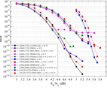
Fig.4 shows the performance for NMSA and the and the proposed second minimum
approx-imation MSA (SMA-MSA) quantized with 7 bits for the (2048, 1723) LDPC code, applied to
the IEEE 802.3an standard, with parameters dc = 32, dv = 6. It can be seen that our approach
has similar performance in the waterfall region, with just 0.08dB of performance loss up to
BER=10−11, and in the error floor region, from BER=10−11 to BER=10−14, improves 0.2dB the
performance.
The performance of other approaches that estimate the second minimum for the (2048,1723)
LDPC code is also included in Fig. 4. The svwMSA [8] has the same performance as ours in
the waterfall and has better error-floor behaviour.
The (2304, 2048) LDPC code with parametersdc= 36, dv = 6 constructed using the method
proposed in [13] was also tested. As can be seen in Fig. 4 for this code both the waterfall and
the error floor region have almost the same performance, with a difference of less than 0.05dB
between our method and the NMSA.
The algorithms that use the same tree finder as ours, the NPMSA [9] (Fig. 2a) and rExMin-n
[10] (Fig. 2b), have the same (or slightly better) performance as NMSA until BER=10−7 for the
Fig. 3. BER performance of SMA-MSA for the (2048, 1723) LDPC code. Simulations performed with floating-point,Itmax= 20
and early termination.
The (16129,15372) LDPC code with dc = 127 and dv = 6 from [14] was also implemented
and simulated, and its BER is shown in Fig. 4. This code has a special interest due to its very
high rate and its good behaviour in the error floor region, which is remarkable compared to the
rest of high-rate codes. The performance loss of our approximation is almost negligible (0.1
dB) in the waterfall. In addition, it does not introduce any performance degradation in the error
floor region. The decoder was simulated with an FPGA-based hardware emulator during several
months without finding any error at 5.8 dBs (more than 1015 frames were transmitted, which is
equivalent to 1019 bits).
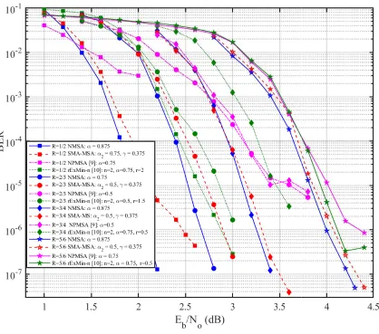
Finally, the LDPC codes of the IEEE 802.11ac/n/g standards were also evaluated and the BER
Fig. 4. BER performance of NMSA, SMA-MSA, PNMSA and rExMin-n for the (2048, 1723), (2304, 2048) LDPC codes
and NMSA and SMA-MSA for the (16129,15372) LDPC codes measuring 25 error-frames. Simulations performed with 7-bit
quantization,Itmax= 20and early termination.
for high-rate codes and that its performance deteriorates as the rate decreases. However, it can
be seen that the performance degradation with the rate is quite more pronounced for the NPMSA
and rExMin-n algorithms.
IV. HARDWARERESULTS ANDCOMPARISONS
Two SMA-MSA decoders for the (2048, 1723) and the (16129,15372) LDPC codes were
implemented using partial-parallel layered architectures as the one from [8]. As both codes have
Fig. 5. BER performance of NMSA, SMA-MSA, PNMSA and rExMin-n for the LDPC codes of IEEE 802.11ac/n/g, rates 1/2,
2/3, 3/4 and 5/6, measuring 25 error-frames. Simulations performed with 7-bit quantization,Itmax= 20and early termination.
means that 64 and 127 check nodes were parallelized for the (2048,1723) code and (16129,15372)
code, respectively. Therefore, their throughput is calculated as T hr=N·fclk/(6·Itavg), where
Itavg is the average number of iterations. VHDL was used for the description of the hardware.
Cadence RTL Compiler and SOC encounter tools were employed for synthesis and place and
route, respectively, with a 90nm CMOS process of nine layers with standard cells at 1.2V.
The obtained results for the (2048, 1723) LDPC code are summarized in Table II together with
3 of the most efficient partial-parallel layered architecture (PPLA) decoders found in literature for
the same code, an NMSA decoder, which uses the 2 minimum true finder of Fig. 1a, implemented
with the same PPLA as the one of SMA-MSA and 3 of the most efficient full-parallel architecture
TABLE II
IMPLEMENTATION RESULTS FOR THE (2048,1723) LDPC CODE
Decoder-Arch.
SNR/It @BER 10−7
(dBs/#Itavg)
It max
Tech.@Volt. (nm@V)
Area (mm2)
Freq. (MHz)
Thr. (Gbps)
TAR (Gbps /mm2)
This worka-PPLA 4.3/6.2 20 [email protected] 3.15 202 11.2 3.55
NMSAa-PPLA 4.2/5.8 20 [email protected] 4.84 121 7.1 1.47
svwMSA [8]a-PPLA 4.2/6 20 [email protected] 3.84 226 12.8 3.34
NMSA [15]a-PPLA 4.3/6 - [email protected] 5.35 137 7.79 1.45
NMSA [16]ab-PPLA 4.3/5 - [email protected] 9.2 348 11.85 1.28 SR-NMSA [17]ab-FPA 4.5/4.3 11 [email protected] 9.68 156 67.02 6.92
NPMSA [9]a-FPA 4.4/3.5 9 [email protected] 9.6 199.6 116.8 12.17
CBFS [18]a-FPA 4.4/39 500 90@1 4.12 749 39.3 9.53
UFAMPA [19]a-UFPA 5/- 5 22@1 16.2 862 588 1.1b a
Post-place & route results
b
Results scaled for 90nm
are unrolled to obtain a very high throughput. Table II also includes the SNR values and the
average number of iterations (Itavg) at BER=10−7, which are used to measure the throughput (Thr) and efficiency in terms of throughput-area ratio (TAR).
If we compare our decoder with the NMSA with the same PPLA, we can see that the area
saving is about 35% and the maximum frequency is increased about 57%, and the TAR efficiency
is twice larger by just introducing our estimation of the second minimum in the decoder. Here,
the difference in area and critical path of using the true two-minimum finder 12TF (Fig. 1a) or
the pseudo second-minimum finder 1P2F (Fig. 1b) is manifested.
The svwMSA [8], which is other approximation of the second minimum, has the lowest area
and highest throughput and is the most TAR efficient among the other PPLA decoders. Compared
to svwMSA, our proposal saves 18% of area due to the fact that it does not require to store
and control the use of different correction factors for the different iteration’s range. Although
SMA-MSA is slower (12.5%), is more TAR efficient (6%) and, besides, it does not require a
complex optimization of parameters that changes with iterations or with the SNR, so it reduces
the time of design without sacrificing hardware advantages.
If we compare with the FPA decoders, all of them are more TAR efficient than all the layered
TABLE III
IMPLEMENTATION RESULTS FOR THE (16129,15372) LDPC CODE DECODERS WITH PPLA IN A 90NM
PROCESS
Decoder
Area
(mm2)
Freq.
(MHz)
Thr. (Gbps)
(15it)/(10it)/(5it) TAR
(Gbps/mm2)
This work 14.17 48 8.6/12.9/25.8 0.61
NMSA 15.91 37.23 6.67/10/20 0.42
estimator of Fig. 2a, and whose TAR is 3.5 times higher than the one of SMA-MSA. The
CBFS decoder [18] is 2.7 times more efficient than SMA-MSA. However, the performance of
both decoders, the CBFS and NPMSA, is deteriorated for high SNR: the early degradation of
CBFS arises at BER=4·10−10 (Fig. 22 from [18]) and the one of NPMSA at BER=10−7 (Fig.
4). SMA-MSA is about 1.9 times less TAR efficient than Split-row decoder [17] with better
BER performance. On the other hand, it is worth mentioning that the proposed approximation
for the second minimum can be applied to full-parallel architectures. For example, if it were
used to replace the check node (Fig. 2a) of the NPMSA decoder [9], it would take benefit from
all the architectural improvements of the NPMSA decoder with a small area overhead and the
BER performance would improve at high SNR values. On the other hand, compared with the
UFAMPA [19] decoder with UFPA, our proposal is 3,2 times more TAR efficient and has better
BER performance (UFAMPA has 0.7 dBs of BER performance loss).
For the (16129, 15372) LDPC code, we can see in Table III that the decoders reach a lower
clock frequency than the ones designed for the (2048, 1723) LDPC code. This is because the
degree of the check node is 127, so the critical path is higher, and, in addition, the routing
congestion of the decoder is also higher due to its large size. The results of Table III shows
how the SMA-MSA decoder requires lower area (10.8%) and increases the throughput (28.9%)
compared to the NMSA decoder with the same PPLA using the true minimum finder 12TF (Fig.
1a). It is important to remark that our simulations showed that this decoder does not introduce
any performance degradation for BER<10−15 and the coding gain in the waterfall is almost the
V. CONCLUSIONS
In this paper a new approximation to estimate the second minimum of an LDPC check node
processor is introduced. The approximation is suited for high-rate LDPC codes and improves
the BER performance in the error-floor region of other approaches based on the use of a
first-minimum and pseudo second-first-minimum finder instead of a true two-first-minimum finder in the
min-sum algorithm. The increase in area-throughput efficiency of our proposed check-node unit will
improve with independence of the selected architecture and it will be larger compared to
Min-sum as the check-node degree/rate increases. The derived architectures improve the efficiency
of the Min-sum decoder between 18% and 42% in terms of throughput-area ratio.
REFERENCES
[1] R. Gallager, “Low-density parity-check codes,”IRE Transactions on Information Theory, vol. 8, no. 1, pp. 21–28, January
1962.
[2] F. Kschischang, B. Frey, and H.-A. Loeliger, “Factor graphs and the sum-product algorithm,” IEEE Transactions on
Information Theory, vol. 47, no. 2, pp. 498–519, Feb 2001.
[3] J. Chen, A. Dholakia, E. Eleftheriou, M. Fossorier, and X.-Y. Hu, “Reduced-Complexity Decoding of LDPC Codes,”IEEE
Transactions on Communications, vol. 53, no. 8, pp. 1288–1299, Aug 2005.
[4] L. Amaru, M. Martina, and G. Masera, “High Speed Architectures for Finding the First two Maximum/Minimum Values,”
IEEE Transactions on Very Large Scale Integration (VLSI) Systems, vol. 20, no. 12, pp. 2342–2346, Dec 2012.
[5] Y. Lee, B. Kim, J. Jung, and I. C. Park, “Low-complexity tree architecture for finding the first two minima,” IEEE
Transactions on Circuits and Systems II: Express Briefs, vol. 62, no. 1, pp. 61–64, Jan 2015.
[6] A. Darabiha, A. Carusone, and F. Kschischang, “A bit-serial approximate min-sum LDPC decoder and FPGA
implemen-tation,” inIEEE International Symposium on Circuits and Systems, 2006. ISCAS 2006, May 2006, pp. 4 pp.–.
[7] C. Zhang, Z. Wang, J. Sha, L. Li, and J. Lin, “Flexible LDPC Decoder Design for Multigigabit-per-Second Applications,”
IEEE Transactions on Circuits and Systems I: Regular Papers, vol. 57, no. 1, pp. 116–124, Jan 2010.
[8] F. Angarita, J. Valls, V. Almenar, and V. Torres, “Reduced-Complexity Min-Sum Algorithm for Decoding LDPC Codes
With Low Error-Floor,”IEEE Transactions on Circuits and Systems I: Regular Papers, vol. 61, no. 7, pp. 2150–2158, July
2014.
[9] C. C. Cheng, J. D. Yang, H. C. Lee, C. H. Yang, and Y. L. Ueng, “A fully parallel ldpc decoder architecture using
probabilistic min-sum algorithm for high-throughput applications,”IEEE Transactions on Circuits and Systems I: Regular
Papers, vol. 61, no. 9, pp. 2738–2746, Sept 2014.
[10] I. Tsatsaragkos and V. Paliouras, “Approximate algorithms for identifying minima on min-sum ldpc decoders and their
hardware implementation,” IEEE Transactions on Circuits and Systems II: Express Briefs, vol. 62, no. 8, pp. 766–770,
Aug 2015.
[11] J. O. Lacruz, F. Garca-Herrero, J. Valls, and D. Declercq, “One minimum only trellis decoder for non-binary low-density
parity-check codes,”IEEE Transactions on Circuits and Systems I: Regular Papers, vol. 62, no. 1, pp. 177–184, Jan 2015.
[12] F. Angarita, V. Torres, A. Perez-Pascual, and J. Valls, “High-throughput FPGA-based emulator for structured LDPC codes,”
[13] B. Zhou, J. Kang, S. Song, S. Lin, K. Abdel-Ghaffar, and M. Xu, “Construction of non-binary quasi-cyclic LDPC codes
by arrays and array dispersions,”IEEE Transactions on Communications, vol. 57, no. 6, pp. 1652–1662, Jun. 2009.
[14] Q. Diao, J. Li, S. Lin, and I. F. Blake, “New classes of partial geometries and their associated ldpc codes,”IEEE Transactions
on Information Theory, vol. 62, no. 6, pp. 2947–2965, June 2016.
[15] A. Cevrero, Y. Leblebici, P. Ienne, and A. Burg, “A 5.35 mm2 10GBASE-T Ethernet LDPC decoder chip in 90 nm CMOS,”
in IEEE Asian Solid State Circuits Conference (A-SSCC), 2010, Nov 2010, pp. 1–4.
[16] D. Bao, X. Chen, Y. Huang, C. Wu, Y. Chen, and X.-Y. Zeng, “A single-routing layered LDPC decoder for 10Gbase-T
Ethernet in 130nm CMOS,” in17th Asia and South Pacific Design Automation Conference (ASP-DAC), 2012, Jan 2012,
pp. 565–566.
[17] T. Mohsenin, D. Truong, and B. Baas, “A Low-Complexity Message-Passing Algorithm for Reduced Routing Congestion
in LDPC Decoders,”IEEE Transactions on Circuits and Systems I: Regular Papers, vol. 57, no. 5, pp. 1048–1061, May
2010.
[18] Y. L. Ueng, C. Y. Wang, and M. R. Li, “An efficient combined bit-flipping and stochastic ldpc decoder using improved
probability tracers,”IEEE Transactions on Signal Processing, vol. 65, no. 20, pp. 5368–5380, Oct 2017.
[19] R. Ghanaatian, A. Balatsoukas-Stimming, T. C. Mller, M. Meidlinger, G. Matz, A. Teman, and A. Burg, “A 588-gb/s ldpc
decoder based on finite-alphabet message passing,” IEEE Transactions on Very Large Scale Integration (VLSI) Systems,
![Fig. 2. Second minimum estimators based on 12TF: a) Probabilistic second minimum from [9], b) rExMin-n from [10] and c)](https://thumb-us.123doks.com/thumbv2/123dok_us/1107828.1611862/7.612.154.499.68.367/second-minimum-estimators-based-probabilistic-second-minimum-rexmin.webp)