MOTOR USING GENETIC ALGORITHMS
Adzua Peter Terseer1 and Engr. Dr. Goshwe Nentawe Yilwatda2
1,2
Department of Electrical/Electronics Engineering, University of Agriculture Makurdi, Nigeria
Abstract-Induction motors serve a very essential function in the industrial sector. In fields and drives especially, the induction motor becomes the most important tool. If the speed of an induction motor is not properly controlled, it becomes quite handy to achieve desired tasks with specific applications. Several conventional techniques to control the speed of an induction motor exist. However, these conventional techniques don’t do so well under a wide range of conditions due to their sensitivity to parameter variations. This paper has therefore demonstrated a strategy to improve the speed control capabilities of induction motors by using speed controllers based on artificial intelligence techniques like Genetic Algorithms. This objective is actualized using the versatile utilities of MATLAB/SIMULINK. The speed, torque and statorcurrents are observed for induction motor simulated with conventional and GA based controllers. Results obtained while using Genetic Algorithm based controllers demonstrate superior control capabilities
Keywords-Genetic Algorithm, Induction Motor,Objective Function,Speed Control, Stator Current, Torque
I. INTRODUCTION
An induction motor is an alternating current (ac) powered asynchronous motor whose rotor winding is powered by electromagnetic induction from the magnetic field of the stator winding.
In industrialization, induction motors play a vital role. The fact that manufacturers constantly sought to minimize cost and avoid low efficiency has made variable motor speed technology become so important in order to improve efficiency, cut down the cost of production and also reduce noise. Without proper motor speed control, it is also practically impossible to achieve the desired task for a particular application. Motor speed is therefore, necessary in order to enhance maximum torque and efficiency [2,4].
Previously, fixed gain PI and PID controllers were chiefly used for the speed control of induction motors. However, the fact that such conventional control methods don’t do well under wide range of operational conditions due to their sensitivity to parameter variations [5,8,15], Artificial Intelligence based controllers like Fuzzy logic, Adaptive Neuro Fuzzy Inference System (ANFIS) and Genetic Algorithms (GA) have been deployed.
Genetic algorithms (GA) employ the principle of natural selection and genetics which is a stochastic global search method that mimics the process of natural evolution. GA locates high performance areas in complex domains without experiencing the difficulties associated with dimensionality or false optima as may occur with conventional techniques [3,6].
The main aim of this paper is to enhance the speed control of an induction motor using genetic algorithm techniques. Objectively, it aims to show the dynamic performance of an induction motor in terms of torque, rotor speed and stator currents when Genetic Algorithm Controller is used then compare the dynamic performances with the conventional controller and show improvements.
II. SPEED CONTROL TECHNIQUES
From the list above, power recovery and rotor resistance control apply only to wound rotor motors since they are basically controlled within the rotor circuit. Pole changing applies only to squirrel cage motors whereas control of supply frequency and stator voltage are both applicable to squirrel cage and wound rotor motors
To analyse and model induction motors, it is important to use their per phase equivalent circuit shown inFigure 1
III. DYNAMIC INDUCTION MOTOR MODELLING
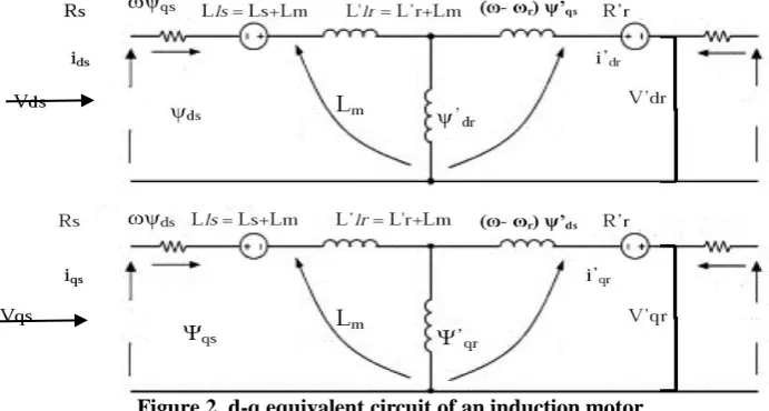
The torque and voltage equations that describe an induction motor’s dynamic behaviour are time varying and quite complex. Therefore, time varying inductances can be eliminated by reducing a poly phase winding with a d-q two phase winding thereby forming their magnetic axes in quadrature as shown inFigure 2 [10,13,14].
Figure 2. d-q equivalent circuit of an induction motor
3.1Inductance Matrix of Induction Motor
As evident in figure 3, stator inductance Ls, and rotor inductance Lr, are respectively defined as
𝐿𝑠 = 𝐿𝑙𝑠 + 𝐿𝑚 (1)
𝐿𝑟 = 𝐿𝑙𝑟 + 𝐿𝑚 (2)
Where
𝐿𝑙𝑠 =𝑋𝑠 ω is Stator leakage inductance
𝐿𝑚is magnetizing inductance and
𝐿𝑙𝑟 =𝑋𝑟 ω is rotor leakage inductance
However, the rotating electromotive force in figure 3 are not represented by inductances but by voltage sources. Therefore, the associated flux voltage and current equations are shown as follows;
Ψ𝑞𝑠 = 𝐿𝑠i𝑞𝑠 + 𝐿𝑚i𝑞𝑟 (3)
Ψ𝑑𝑠 = 𝐿𝑚i𝑑𝑟 + 𝐿𝑠i𝑑𝑠 (4)
Ls Lsr Rrs
Ψ𝑑𝑟 = 𝐿𝑟i𝑑𝑟 + 𝐿𝑚i𝑑𝑠 (6)
The voltage equations therefore are
V𝑞𝑠 = 𝑅𝑠i𝑞𝑠 + 𝑑Ψ𝑞𝑠
𝑑𝑡 + ωΨ𝑑𝑠 (7)
V𝑑𝑠 = 𝑅𝑠i𝑑𝑠 + 𝑑Ψ𝑑𝑡𝑑𝑠 − ωΨ𝑞𝑠 (8)
V𝑞𝑟 = 𝑅𝑟i𝑞𝑟 + 𝑑Ψ𝑞𝑟
𝑑𝑡 + (ω − ω𝑟)Ψ𝑑𝑠 (9)
V𝑑𝑟 = 𝑅𝑟i𝑑𝑟 + 𝑑Ψ𝑑𝑡𝑑𝑟 − (ω − ω𝑟)Ψ𝑞𝑠 (10)
Where
Ψ𝑞𝑠, Ψ𝑑𝑠 are the stator flux components in q and d axes respectively Ψ𝑞𝑟, Ψ𝑑𝑟 are the rotor flux components in q and d axes respectively V𝑞𝑠, V𝑑𝑠 are the stator voltage components in q and d axes respectively
V𝑞𝑟, V𝑑𝑟 are the rotor voltage components in q and d axes respectively
Therefore, by substituting equations (6) and (7) into equation (10), V𝑞𝑠 becomes
V𝑞𝑠 = 𝑅𝑠i𝑞𝑠+ 𝑑(𝐿𝑠i𝑞𝑠 + 𝐿𝑚i𝑞𝑟)
𝑑𝑡 + ω(𝐿𝑚i𝑑𝑟 + 𝐿𝑠i𝑑𝑠)
V𝑞𝑠 = 𝑅𝑠i𝑞𝑠 + 𝐿𝑠𝑑i𝑞𝑠
𝑑𝑡 + 𝐿𝑚
𝑑i𝑞𝑟
𝑑𝑡 + ω𝐿𝑚i𝑑𝑟 + ω𝐿𝑠i𝑑𝑠 (11)
Similarly
V𝑑𝑠 = 𝑅𝑠i𝑑𝑠 + 𝐿𝑠𝑑i𝑑𝑠
𝑑𝑡 + 𝐿𝑚
𝑑i𝑑𝑟
𝑑𝑡 - ω𝐿𝑠i𝑞𝑠 - ω𝐿𝑚i𝑞𝑟 (12)
V𝑞𝑟 = 𝑅𝑟i𝑞𝑟 + 𝐿𝑟𝑑i𝑑𝑡𝑞𝑟 + 𝐿𝑚𝑑i𝑑𝑡𝑞𝑠 + (ω − ω𝑟)𝐿𝑚i𝑑𝑠 + ω − ω𝑟 𝐿𝑟i𝑑𝑟 (13)
V𝑑𝑟 = 𝑅𝑟i𝑑𝑟 + 𝐿𝑟𝑑i𝑑𝑡𝑑𝑟 + 𝐿𝑚𝑑i𝑑𝑡𝑑𝑠 - (ω − ω𝑟)𝐿𝑚i𝑞𝑠 - (ω − ω𝑟)𝐿𝑟i𝑞𝑟 (14)
However, V𝑑𝑟 and V𝑞𝑟 are shorted. Therefore, they both equal to zero. This implies that in matrix
form, electrical transients of currents and voltages can be given as
V𝑞𝑠 V𝑑𝑠 0 0 = 𝑅𝑠 + 𝐿𝑠𝑃 ω𝐿𝑠 𝐿𝑚𝑃 ω𝐿𝑚 −ω𝐿𝑠 𝑅𝑠+ 𝐿𝑠𝑃 −ω𝐿𝑚 𝐿𝑚𝑃 𝐿𝑚𝑃 (ω − ω𝑟)𝐿𝑚 𝑅𝑟𝐿𝑟𝑃 (ω − ω𝑟)𝐿𝑟 − ω − ω𝑟 𝐿𝑚 𝐿𝑚𝑃 − (ω − ω𝑟)𝐿𝑟 𝑅𝑟𝐿𝑟𝑃 i𝑞𝑠 i𝑑𝑠 i𝑞𝑟 i𝑑𝑟 (15) Where the stationary reference frame operator 𝑑𝑡𝑑 is represented by P.
However, for synchronous frame, ω = ω𝑒
∴ V𝑞𝑠 V𝑑𝑠 0 0 = 𝑅𝑠+ 𝐿𝑠𝑃 ω𝑒𝐿𝑠 𝐿𝑚𝑃 ω𝑒𝐿𝑚 −ω𝑒𝐿𝑠 𝑅𝑠 + 𝐿𝑠𝑃 −ω𝑒𝐿𝑚 𝐿𝑚𝑃 𝐿𝑚𝑃 (ω𝑒 − ω𝑟)𝐿𝑚 𝑅𝑟𝐿𝑟𝑃 (ω𝑒 − ω𝑟)𝐿𝑟 − ω𝑒 − ω𝑟 𝐿𝑚 𝐿𝑚𝑃 − (ω𝑒 − ω𝑟)𝐿𝑟 𝑅𝑟𝐿𝑟𝑃 i𝑞𝑠 i𝑑𝑠 i𝑞𝑟 i𝑑𝑟 (16)
As proposed by Robert H. Park, the equation below is a representation of how abc frame can be transformed into the d-q frame
𝑉𝑑
𝑉𝑞
0
=
𝑐𝑜𝑠θ cos(θ −2𝜋3) cos(θ +2𝜋3)
𝑠𝑖𝑛θ 𝑠𝑖𝑛(θ −2𝜋3) 𝑠𝑖𝑛(θ +2𝜋3)
0.5 0.5 0.5
𝑉𝑎
𝑉𝑏
𝑉𝑐
(17)
The inverse transformation is given as
𝑉𝑎
𝑉𝑏
𝑉𝑐
=
𝑐𝑜𝑠θ 𝑠𝑖𝑛θ 1
cos(θ −2𝜋3) 𝑠𝑖𝑛(θ −2𝜋3) 1
cos(θ +2𝜋3) 𝑠𝑖𝑛(θ +2𝜋3) 1
𝑉𝑑
𝑉𝑞
0
3.2. Torque Equation of an Induction Motor
In vector space, torque equation is given as:
𝑇𝑒 = 32∗𝑃2∗ω1
𝑏(Ψ𝑑𝑠i𝑞𝑠 − Ψ𝑞𝑠i𝑑𝑠)
⟹ 𝑇𝑒 = 34𝑃ω1
𝑏I𝑚(Ψ𝑠I𝑠) (19)
Even though this torque equation is gotten from a stationary reference frame, it applies to other reference frames.
Therefore, can also be written as
𝑇𝑒 = 34𝑃𝑙𝑚
𝐿𝑟𝐼𝑚(𝐼𝑞𝜑𝑟) (20)
3.3.Current Calculations of an Induction Motor
According to figure 3, the stator and rotor current equations in q and d axis can be written as
𝑖𝑞𝑠 =
𝜑𝑞𝑠 − 𝜑𝑚𝑞
𝑋𝑙𝑠 (21)
𝑖𝑑𝑠 = 𝜑𝑑𝑠 − 𝜑𝑋 𝑚𝑑
𝑙𝑠 (22)
𝑖𝑞𝑟 =
𝜑𝑞𝑟 − 𝜑𝑚𝑞
𝑋𝑙𝑠 (23)
𝑖𝑑𝑟 = 𝜑𝑑𝑟 − 𝜑𝑋 𝑚𝑑
𝑙𝑠 (24)
Considering the current flow and having 𝑖 = 𝜑𝑋, when 𝜑 = 𝜑𝑚𝑞 and 𝜑 = 𝜑𝑚𝑑 ,
𝜑𝑚𝑞 = 𝑋𝑚𝑙 𝜑𝑋𝑞𝑠
𝑙𝑠 +
𝜑𝑞𝑟
𝑋𝑙𝑟 (25)
𝜑𝑚𝑑 = 𝑋𝑚𝑙 𝜑𝑋𝑑𝑠
𝑙𝑠 +
𝜑𝑑𝑟
𝑋𝑙𝑟 (26)
𝑋𝑚𝑙 = 1 1
𝑋 𝑚 + 1 𝑋 𝑙𝑠 + 1 𝑋 𝑙𝑟 (27)
With regards to equations (10), (11), (12), (13), the flux linkage equations can be written as
1
ω𝑏
𝑑𝜑𝑞𝑠
𝑑𝑡 = V𝑞𝑠 −
ω𝑒
ω𝑏𝜑𝑑𝑠 − 𝑅𝑠i𝑞𝑠
⟹ ω1
𝑏
𝑑𝜑𝑞𝑠
𝑑𝑡 = V𝑞𝑠−
ω𝑒
ω𝑏𝜑𝑑𝑠 +
𝑅𝑠
𝑋𝑙𝑠(𝜑𝑚𝑞 − 𝜑𝑞𝑠) (28)
1
ω𝑏
𝑑𝜑𝑑𝑠
𝑑𝑡 = V𝑑𝑠 −
ω𝑒
ω𝑏𝜑𝑞𝑠 − 𝑅𝑠i𝑑𝑠
⟹ ω1
𝑏
𝑑𝜑𝑑𝑠
𝑑𝑡 = V𝑑𝑠 −
ω𝑒
ω𝑏𝜑𝑞𝑠 +
𝑅𝑠
𝑋𝑙𝑠(𝜑𝑚𝑑 − 𝜑𝑑𝑠) (29)
Similarly,
1
ω𝑏
𝑑𝜑𝑞𝑟
𝑑𝑡 = V𝑞𝑟 −
(ω𝑒−ω 𝑟)
ω𝑏 𝜑𝑑𝑟 +
𝑅𝑠
𝑋𝑙𝑠(𝜑𝑚𝑞 − 𝜑𝑞𝑟) (30)
And
1
ω𝑏
𝑑𝜑𝑑𝑟
𝑑𝑡 = V𝑑𝑟 −
(ω𝑒−ω 𝑟)
ω𝑏 𝜑𝑞𝑟 +
𝑅𝑠
𝑋𝑙𝑠(𝜑𝑚𝑑 − 𝜑𝑑𝑟) (31)
3.4. Rotor Speed of an Induction Motor
The rotor speed ω𝑟 and the motor torque are related in equation (35) below
𝑇𝑒 = 𝑇𝑙𝑜𝑎𝑑 + 𝐽𝑑𝑤𝑚𝑑𝑡 = 𝑇𝑙𝑜𝑎𝑑 +2𝐽𝑝 ∗𝑑𝑑𝑡 𝜔𝑟 (32)
Which makes
𝜔𝑟 = 2𝐽𝑝 𝑇𝑒 − 𝑇𝑙 (33)
Where:
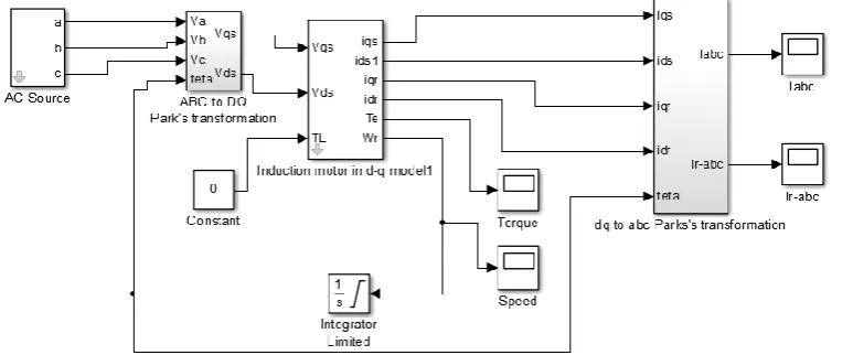
With respect to equations 1-33 above, the simulation of the induction motor with the conventional controller in MATLAB/SIMULINK is depicted in figure 3 below.
Figure 3.Conventional Induction Motor Simulation in MATLAB/SIMULINK
V. GENETIC ALGORITHMS
Genetic algorithm is an optimization technique in computing that finds exact or nearly exact solutions to search problems. It is a global search heuristic. This is a class of evolutionary algorithm technique inspired by evolutional biology like crossover, mutation, inheritance and selection. GA is implemented in simulations where a population of individual’s solution to an optimization problem evolves towards better solutions. Typically, binary strings of Os and 1s represent solutions [3].
The evolution begins with a population of randomly generated individuals and takes place in generations. It begins with no knowledge of the actual solution and depends wholly on environmental and operator responses to achieve the best solution. The fitness of each individual in each population of each generation is evaluated and multiple individuals are stochastically selected based on their fitness, recombined and randomly mutated to form a new population. The resultant population is once again iterated. The algorithm halts when the maximum number of generations is reached or a desired fitness level attained for the population.
Traditionally, Genetic Algorithm requires
a. A genetic representation of the solution domain. b. A fitness function to evaluate the solution domain.
Genetic Algorithm is based on Charles Darwin’s principle of the survivor of the fittest. The individuals that can survive, live while others die. The principle is ideal for finding fitness values, f(x). The fitness function is an assigned numerical score that indicates how well a particular solution solves the problem. It represents the adaptability capability of the individual to the environment.
5.1. Implementing genetic algorithms
In order to reduce power loss in the motor, a PWM inverter is introduced in this model. This pulse width modulation inverter is responsible for controlling the power supplied to the motor. The average value of voltage and current supplied to the motor is controlled by turning ON and OFF the switch between supply and load at a fast rate [9,11,16].
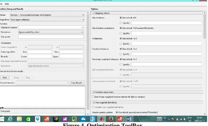
To implement Genetic Algorithms in MATLAB, the optimization toolbox is used according to the following steps with the screen shot of figure 4.
1. on the MATLAB command line, the optimization toolbox is invoked by typing optimtool
Figure 4. Optimization ToolBox
2. The solver is set to Genetic Algorithm
3. The Objective function is entered as “@GA_obj_ftn”. This summarizes and assigns a figure showing how close a particular chromosome is to achieving the set aims of the problem at hand. In this research work, the objective function determines the best PID controller that produces the fastest rise and settling times. It is thus created according to equation
𝐶𝑝𝑖𝑑 =𝐾𝐷𝑆
2+𝐾 𝑃𝑆+𝐾1
𝑆 (34)
4. According to equation (34), the objective function has three variables (P,I,D). Therefore, the number of variables is set to 3.
5. The lower and upper bound limits are set to 2 and 100 respectively.
6. The population size is set to 120. This refers to the number of chromosomes involved in the iteration.
7. Population type is set to double vector
8. The initial population, scores and range are set to default.
9. Fitness scaling is set to RANK in order to prevent premature convergence (This determines how fit an individual solution is for selection)
10. Stochastic Uniform selection method is preferred in order to give weaker members of the population (according to their fitness) a chance to be chosen and thus reduce the unfair nature of fitness-proportional selection methods. (Selection is the stage of a genetic algorithm at which individual genomes are chosen from a population for future recombination/crossover).
11. Elite count is set to 4; this specifies the number of individuals that are guaranteed to survive to the next generation
12. A crossover fraction of 0.8 is used to show the fraction of the next generation, other than elite children, that are produced by crossover. (Crossover performs sexual genetic recombination).
13. Mutation function is set to constraint dependent. This is the probability with which all bit positions of all chromosomes in a new population undergo a random change after the process of selection.
14. The crossover function is set to “arithmetic” in order to create children that are the weighted arithmetic mean of the two parents
15. The migration fraction and interval are both set to 0.2 and 20 respectively
16. The initial constraint penalty and penalty factor are set to 10 and 100 respectively. 17. The stopping criteria is set to 120 generations
20. When the algorithm terminates, the backend code responsible for the simulation of the algorithm is generated by clicking on file, then Generate code. The generated code is subsequently saved as “ga_code.m”
21. This code is then embedded in a MATLAB function block and it replaces the conventional controller of Error! Reference source not found.as the GA controller as shown in Figure 5 below
Figure 5. Induction motor with GA controller
22. Thereafter, the entire motor is simulated and results observed and compared with the conventional controllers
VI. RESULTS AND DISCUSSIONS
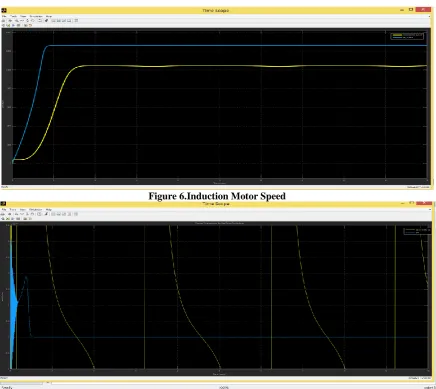
Figure 6.Induction Motor Speed
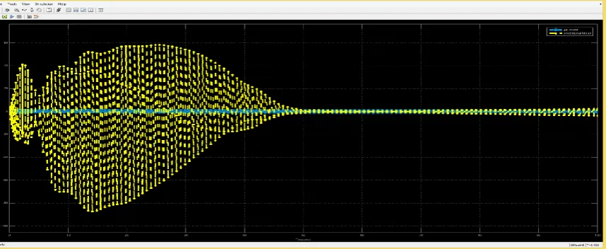
Figure 8.Induction Motor Stator Current
From Figure 6, it is apparent that even though the results are taken in the same time line, the speed increases while the speed rise time drastically reduces as the genetic algorithm based controller is introduced. While the rise time is quite slow with the conventional controller due to the observed obvious ripples to speed response, a massive improvement is observed when the Genetic Algorithm based controller is employed. The settling time just like the rise time reduces as the GA based controlleris introduced.
With regards to computational time, it is also apparent that the conventional controller takes a longer time to reach its peak as compared to the GA based controller.
More also, with GA based controller, there are negligible ripples in speed response as compared to the conventional controller.
Furthermore, as it is clear to see in Figure 7, converging to zero in GA based controller is happening intensively in less duration of time. Unlike the GA based controller where the torque oscillations are reduced and decay more rapidly, worrying oscillations occur in the torque response of the conventional controller before it finally settles down.
With regards to Figure 8, the induction motor with conventional controller requires very high startup current and once it has started, it exhibits a higher degree of stator current ripples (current imbalance). Whereas, the GA based controllerhas smoothened the ripples in the motor torque and stator currents. The GA based controllerhas exhibited very low (acceptable) startup current which took lesser time to settle as compared to its conventional counterpart.
VII. CONCLUSION
Computer based simulations have been successfully carried out for induction motor speed control using an induction motor with a conventional and Genetic Algorithm based controller.At the end of the simulation therefore, it is found thatthe genetic algorithm based controller has yielded better results. It has yielded the highest speed in the shortest time with no ripples to speed response, its torque convergence to zero is the quickest and at startup, it has exhibited very low stator current that balanced up in the shortest time.
REFERENCES
[1] K. Anitha, G. Santosh, L. Suneel, K. Spandana, and E. Raviteja, Simulation and Speed Control of 3-Phase Induction
Motor Drives. International Journal of Engineering Science and Computing, 2016, ISSN 2321 336
[2] L. M. Barazane and R. Ouiguini,ANFIS Speed Controller for Vector Control of an Induction Motor. EFEEA’10 International Symposium on Environment Friendly Energies in Electrical ApplicationsGhardaïa, Algeria, 2010. [3] E. G. Carrano, R. H. C. Takahashi, W. M. Caminhas and O. M. Neto, A Genetic Algorithm for Multiobjective
Training of ANFIS Fuzzy Networks. Congr. Evol. Comput. pp. 3259-3265, 2008.
[4] R. Divya, S. Swati, and B. Vijay, Fuzzy Speed Controller Design of Three Phase Induction Motor. International Journal of Emerging Technology and Advanced Engineering ISSN 2250-2459, 2012, Volume 2, Issue 5.
[6] K. M. Indurupalli,k. S. R. Anjaneyulu and B. V. Prashanth, Design of Robust Speed Controller by Optimization Techniques for DTC IM Drive. International Journal of Computer Networks and Communications Security, 2013, VOL. 1, NO. 1.
[7] B. Iulian, M. Virgil, P. Sorin, and R. Calin, Indirect Vector Control of an Induction Motor with Fuzzy-Logic based Speed Controller. 3rd International Symposium on Electrical Engineering and Energy Converters Suceava, 2009. [8] L. M. Madhav, and S. P. Muley. Induction Motor Speed Control using PID Controller. International Journal of
Technology and Engineering Science Vol 1(2), pp151-155
[9] M. Meenakshi and K. Vinay, Asynchronous Machine Modelling using Simulink fed by PWM Inverter. International
Journal of Advances in Engineering & Technology, 2011, ISSN: 2231-1963
[10]H. M. Mohamadand G. K. Pouria, A New Simulation of Induction Motor. Australasian Universities Power Engineering Conference, (AUPEC), pp. 1-6, 2008.
[11]A. Nabae,S. Ogasawara and H. Akagi, A novel control scheme for current-controlled PWM inverters. IEEE Trans.
on Industry Applic. , vol.22, no. 4. Pp. 697-701, 1986.
[12]D. B. Shashank and P. D. Gajanan, ANFIS Control Scheme for the Speed Control of the Induction Motor. Int. Journal of Engineering Research and Applications ISSN: 2248-9622, Vol. 4, Issue 3 (Version 1), pp.35-39 2014.
[13]D. B. Shashank and P. D. Gajanan, Design of Simulink Model with ANFIS Controller for Controlling Parameters of
3Phase Induction Motor Drives. International Journal of Advanced Research in Computer Science and Software Engineering, 2014, Volume 4, Issue 4.
[14]S. A. Sifatand M. B. Rashid, Direct Quadrate (D-Q) Modeling of 3-Phase InductionMotor Using MatLab / Simulink.
Canadian Journal on Electrical and Electronics Engineering, 2012, Vol. 3, No. 5
[15]S. Swati and B. Amol, Discrete PI and PID Controller Based Three Phase Induction Motor Drive: A Review. International Journal of Electrical, Electronics ISSN No. (Online): 2277-2626 and Computer Engineering 2(2): pp 97-100, 2013.