Dhatrak et al. World Journal of Engineering Research and Technology
IMPROVING EFFICIENCY OF APRON FEEDER BY INSTALLING
SPEED SENSING SWITCH
Dr. Rajendra K. Dhatrak*1 and Minal Salam2
1
Associate Professor and Head, Department of Electrical Engineering, Rajiv Gandhi College
of Engineering, Research and Technology, Chandrapur, Maharashtra, India.
Associate Member of Institution of Engineers, Kolkata, India.
Article Received on 13/09/2019 Article Revised on 23/10/2019 Article Accepted on 03/11/2019
ABSTRACT
Apron feeders are very important in the Coal Handling plant and it
plays vital role in coal unloading from Wagon Tippler to conveyers.
The control system used for these Apron feeders is important for
operating safe. But in some Coal Handling Plant still use of simple
on/off switches for controlling the apron feeders. And these switches
are only play roll of protection up to some limit. These Apron feeders
control system are one of the biggest problem for the plant operator
and maintenance engineers, being the cause of unsafe plant operation, which forced to plant
breakdown and interrupt coal supply to boiler result loss of generation. Hence the efficiency
of plant get reduces. This paper has been focused on required Apron feeders’ control and
indication and alarming by installing a Zero Speed Switch with a Proximity sensors, which
will fulfill requirement of smooth and safe plant operation.
KEYWORD: ZSS, Apron Feeder, coal choke up, Wagon Tippler.
I. INTRODUCTION
The efficiency of Coal Handling is depending upon availability and reliability of Apron
feeders and conveyor system. If both systems is working well then the reliability of CHP is
almost 100 %. Apron feeder is installed next to Wagon tippler and it plays vital role in coal
World Journal of Engineering Research and Technology
WJERT
www.wjert.org
SJIF Impact Factor: 5.924
*Corresponding Author
Dr. R. K. Dhatrak
Associate Professor and
Head, Department of
Electrical Engineering,
Rajiv Gandhi College of
Engineering, Research and
Technology, Chandrapur,
unloading recruitment for power generation for Thermal Power Plant. The coal is unloaded to
Wagon Tippler is transferred to Apron Feeders. The Apron Feeder is hydraulic driven and
has electrical motor for the hydraulic power back. The coal transferred from Wagon Tippler
to Hoper is approximately 65 to 75 tons. The speed of Apron feeders drive is variable which
varies with hydraulic pressure from 40 to 280 kg/sq.cm If the coal is accumulated in the Coal
Hooper and hence the fails to operate or run then Wagon Tippler does not get any indication
or alarm of failure of Apron feeder drive and if the operator does not know this condition and
allows makes Wagon Tippler to unload coal in Coal Hooper, then there is a heavy coal
chock up in Coal Hooper, which requires to clean approximately 48 to 72 hours sometime.
The Zero Speed Switch will be provide for checking speed and indication and alarm
of speed of Apron feeder drive when Apron feeders fails to run or either in running
condition. This ensures the reliability of coal handling plant.
II. EXISTING FAULT
Discontinued Coal Feeding Through Apron Feeder
Coal in the Coal Handling Plant comes through Three ways. They are 1. Road-ways. 2.
Railways. 3. Ropeways. The most prior and important incoming supply of coal is through the
Railways. The coal through the Railway is unloaded at the Coal Unloading Point with the
help of Different feeders consisting of 1.Vibrating feeder. 2. Paddle feeder. 3. Apron feeder.
Here the Unloading of coal coming through Railways is undertaken by the WAGON
TIPPLER department (The most important and huge Quantity of coal Unloading point).
Wagon Tippler section carries out this procedure of Unloading and Further feeding of coal
with the help of conveyor belts. Our fault is located at the APRON FEEDER which use to
feed the huge quantity of coal through its Biggest width "Tribal Conveyor". TRIBAL
CONVEYOR at the Apron feeder has the biggest width of 2200mm belt. Its working is
carried out by 5kw motor with rated current of 7.5 Amp. Discontinued Coal feeding through
Apron Feeder leads to face a very huge loss in overall energy generation through the plant.
This problem of discontinued coal feeding at the Apron feeder occurs due to the Trouble shooting of “Tribal Conveyor" of the Apron feeder .If the Tribal conveyor sometime fails to Carry the incoming quantity of coal from the Coal Hopper, In such cases the “Coal Chute" Of
the Apron feeder gets Choke up with the Choke up of Tribal conveyor. In such cases the
thing use to happen is that the Wagon Tippler Operator in the control room has no
information about the coal chute choke up of Apron feeder. This choke up of coal chute
amount of coals at saturated at the coal chute which priory requires 3-4 working days to clean
the Tribal conveyor and coal chute to obtain its proper operating condition. This leads to the
discontinuity in the feeding of coal to the further Unloading point or boiler maintenance
section, which directly effects on the generation of plant and has to suffer with very huge
economical loss. Hence it was very necessary to provide the alarm or notification signal to
the control room operator of wagon Tippler so that he must stop feeding the coal to the
hopper in case of problem of coal chute choke up so that this choke up must be overcome .
Due to which the continuous power generation would not be affected or suffer practically and
economically too.
III. OVERCOME THE PROBLEM OF COAL CHOKE UP
The problem of coal chock up at Apron feeder is removed by installing a Zero Speed switch
with proximity sensor.
A. What is ZSS?
The zero speed switch i.e. ZSS is used to detect the absence or presence of motion of rotating,
reciprocating or conveying equipment. Means simply it gives the indication where the
equipment is rotate or not, if the equipment is not rotating "absence of speed" it gives the
signal to the PLC panel and operator takes the necessary action. It also gives the signal if the
equipment is rotate properly means "presence of speed" to the PLC panel and operator is
considered our working operation is in safe zone. The ZSS consists of a circuit card and
magnet assembly potted in the probe body. The ZSS is powered from the line voltage and
provides a set of dry relay contacts for indication of motion. The probe must be aimed at a
ferromagnetic material or target on the equipment in order to sense motion. The system
comprises of a suitable motion detector probe and electronic circuitry for detecting zero
speed.
The circuit consists of a step down transformer, a rectifier, a filter and a DC regulated power
supply. It consists of a delay circuit that provides starting time delay and a re-triggerable
timing circuit, which compares the time between two pulses with a fixed time duration. The
sensor circuit senses the moving target and outputs pulses, whose frequency is proportional to
the speed of moving target. Adequate cable entries are provided for wiring. The speed
switches can work in a broad range of temperature with -20°C as the lowest and +60°C being
the highest temperature point. The zero speed can be set from 3 ppm (pulses per min.) to 20
well as during starting of the machine .This is taken care of in the electronics of the ZSS.
There are two types of ZSS, based on supply provision. One is interrupted power supply type,
in which the power supply is given to ZSS only for the duration for which the power is going
to the motor of that machine. In the second type, the power supply is continuously given to
ZSS.
B. Principle
When power is initially applied to the zero speed switch, the alarm relay is energized and
held by the timing circuit for desired (settable) time duration. Whenever the motion detector
sensor detects a target, a signal in the form of pulse re-triggers an internal timing circuit. This
action keeps the alarm relay energized providing a fail-safe operation of the contacts. If no
target is sensed for desired time duration (that is settable), the timing circuit will not be
re-triggered. This will cause the alarm relay to de-energies and the contacts to change state.
Thus the relay output contact can be used for signaling / controlling.
C. Specification
Power : 115V/50-60Hz, 10VA
: 230V/50-60Hz, 10VA
: +10% -10% of rated voltage.
Temperature : -40 to 60 degree Celsius.
Range : 7.8 to 36 mm.
Shifting Weight: 2kg.
Output : 1 from C dry relay contact, rated at 5 amp at 250v ac
D. Installation
The Zero Speed Switch must be mounted in an area that is non-hazardous, within the ambient
temperature range and non-corrosive to the material connection. The Zero Speed Switch is
sensitive to lateral disturbances to its magnetic field. If the Zero Speed Switch is responding
to motion from an interfering target, move the Zero Speed Switch or install a ferrous plate
(steel) as a shield between the Zero Speed Switch and the interfering target. Do not mount the
Zero Speed Switch in direct sunlight without the use of a sun shield.
Zero Speed Switch has four setting keys that are Key 1 - Program (menu)
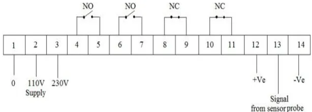
Zero Speed Switch has 14 input/output terminals for different connections as shown fig. 1.
Hardware required for installation and operation of Zero Speed Switch
1. Zero Speed Switch Unit
2. Proximity Metal sensor
3. Indicating Lamp
4. Alarm
5. Electric Terminal Board
6. Welding machine
7. Cables
Fig. 1. Input/output terminals of zero speed switch.
As shown in fig. 3. we are giving supply to 1, 2 and 3 terminals of Zero Speed switch as per
requirement i.e. 1 and 2 for 110 Volts and 1 and 3 terminal is for 230 Volts. Terminal 4, 5, 6
and 7 are taken as normally open (NO) contacts and terminal 8, 9, 10 and 11 are taken as
normally closed (NC) contacts. Terminal 12 and 14 are connected to PLC where Alarm and
Indicator are connected. Separate supply of 24 Volts is given to Alarm and Indicator mounted
on PLC. At terminal 13 signals from proximity metal sensor are taken. Proximity Metal
Sensor is mounted in front of nuts and bolts connected on coupling of Apron Feeder and Gear
Box of Hydraulic machine, and Nuts and Bolts are used as sensing element. This Proximity
sensor Welded properly on the Gear Box at particular position where it exactly face the Nut
and Bolts so that it can sense the speed of Apron feeder. The gap between the metal sensing
probe and the Nuts and bolts should be sufficient such that there is no danger of the Bolts
damaging the sensing probe. The maximum allowable gap is 38 mm, and effective gap
between Sensor and Bolts is 7.8 mm. Where possible, the sensing probe should be mounted
such that the conduit entry is pointing downward to avoid accumulation of condensate in the
casing. Connection of the sensing probe should be made via flexible conduit for easier
E. Operation
When power is initially applied to the Zero Speed Switch, the alarm relay is energized and
held artificially by the timing circuit. This will simulate the normal operation of the ZSS for a
start-up delay of 3 ± 1 seconds (or 5 seconds if a jumper is wired across terminal block 1 TB -
7/8). As a ferromagnetic object passes through the probes permanent magnet field, the
distortion of the flux is sensed by the magneto resistive sensor. The sensor modulates the
current through it to produce a pulse which resets an internal timing circuit. This action keeps
the alarm relay energized providing fail-safe operation of the contacts. If no target or change
in flux is sensed for a period of 10 seconds (or 5 seconds if a jumper is wired across terminal
block 1TB-7/8), the timing circuit will not be reset. This will cause the alarm relay to
de-energize and the contacts to change state. Thus the ZSS will not detect the motion of uniform
ferromagnetic masses that do not produce pulses within the period of the time delay on zero
speed.
In this System following Setting are available-
1. ITD
2. CUR
3. NTD
4. RPM
5. PPR
In Run mode we can set the values for different modes-
1. ITD- 10s
This is the initial time delay to start the process. Maximum value can be set as 99 second. To
see this value, press PRG Key in run Mode. Display will show last set value. To set new
value, say 20. Press Up key 2 times, now display will show value as “0002”. Now press shift
key, this will shift the digit toward, now display will shows as “0002”. Now press Enter key
to set this value.
2. CUR
Press Enter keys. It will show zero message on display press enter key. It will show
previously set value. This setting for the 4mA current.(allowed count are 530 to 550). Press enter will display “Span” massage on display press enter again. It is use for the fine tune the
reading value.(e.g. 4800 RPM).
3. NTD
This is Nuisance delay; this is activated when the current RPM goes below the set RPM level.
e.g. If the set RPM value is 10, and suddenly RPM goes below 10. If we set Nuisance delay
as 5 sec. relay will be gets off after 5 sec. To set the value when user press enter key after
setting value for initial delay. Display will show NTD message. Here set desire value by
using Up and shift key combination.
4. RPM
This is reference minimum RPM value to value to keep output relay ON. When RPM goes
below this value, then nuisance delay will get in action. Maximum settable value is 9999.
5. PPR
Pulse per Revolution. In this user can set No. of pulses in single rotation. Maximum value
can set 99.
Fig. 2. Setting keys of Zero Speed Switch.
Fig. 3. Single Line Diagram of Installation of Zero Speed Switch.
CONCLUSION
By installing Zero Speed Switch the speed of apron feeder is controlled and hence the
problem of chock up of coal at Apron Feeder is overcome. And hence we improve the
REFERENCES
1. Fenglion Song , “Analysis of optimization configuration for coal handling system in large power plant” College of Power and Mechanical Engineering Wuhan University, Wuhan,
China, IEEE, pp. 1 – 4, June 2012.
2. Lihua Zhao, “operation and Maintenance of coal handling system in thermal power plant”
School of Mechanical Engineering, Northeast Dianli University, pp. 201 – 204, March
2011.
3. Lihua Zhao. Analyzing and handling of typical belt conveyor faults. Hoisting And
Conveying Machinery, pp. 46-48, oct 2003.
4. Girja Lodhi, “Operation and Maintenance of Crusher House for Coal handling in Thermal Power plant” Madhav Institute of Technology and Science, Gwalior, India, IJMERR, Oct