Design and Implement an Automatic Safety Driving System
Mr. RODDAM SUMANTH KUMAR REDDY 1, Mr. M.VINAY KUMAR2
1
[M.Tech]/ECE, Student, EMBEDDED SYSTEMS (ES), JNTU (A), Anantapuramu, Andhra Pradesh, India
2
M.Tech, Member of Technical Staff, Seer Akademi, Hyderabad, Andhra Pradesh, India.
Abstract—Vehicle driving is very prone to accident due to drowsiness. Because most of the people are losing their lives in the road accidents by the drowsiness. Thus to overcome this problem the project is built around ARM7, LPC2148. Here we are using eye blink sensor and alcohol sensor. By default the vehicle will be in running condition .During this time if the person closes the eyes automatically the vehicle will be in halt condition and even though if the person consumes alcohol, during this moment also the vehicle will stop and the updated message will be displayed on the 16x2 LCD and the message will be transmitted to the authorized person through GSM modem. This project uses regulated 5V, 500mA power supply. 7805 three terminal voltage regulator is used for voltage regulation. Bridge type full wave rectifier is used to rectify the ac output of secondary of 230/12V step down transformer.
Index Terms—ARM 7 Board, MQ3 sensor, LM35 sensor, IR sensor, IR based Eye-blink sensor, EEPROM, GSM, GPS, Keil IDE
Keywords—Alcohol consumption, control room, drowsiness, position, Temperature
I. INTRODUCTION
In this paper, we propose an Automatic safety driving system in which sensors like alcohol sensor, accelerometer, IR sensors are used for detection of drowsiness and alcohol consumption by driver. In addition to that we have used GPS receiver and GSM modem, for communication with the remote control station. The system used in the vehicle will continuously sends the readings obtained from various sensors and current position of the vehicle which will obtain from GPS receiver to the control station. As a result we get immediate information related to the driver’s condition. Detail design criteria with respect to various sensor and system are given. The proposed system will accurately derive that the various parameters and inform control room.
Thus the entire system will be mainly based upon the GSM and also the GPS because the position of the vehicle will be tracked by the GPS and then the latitude and the longitude values will be sent to the mobile through the GSM at here through the Antenna. The GSM is used for the message alerts to the required or the authorized person and saying that the person is in drowsy state .Thus the entire system will be developed on the Keil IDE for the functioning.
Here in the SMS alerts we are also going to send the state of a person like ALCOHOL ALERT and also the DROWSY ALERT and followed by the values of latitude and also the longitude values. Thus the entire messages will be displayed on the board by the LCD Display.
II. PROPOSED SYSTEM ARCHITECTURE
International Journal of Modern Trends in Engineering and Research (IJMTER)
Volume 2, Issue 10, [October– 2015] ISSN (Online):2349–9745 ; ISSN (Print):2393-8161
Drowsy State. If the person consumed the alcohol then the system will be automatically disables its functioning and hence sending the message to the authorized person in a respective manner saying that the person is in drowsy state.
III. OVERVIEW OF THE RELATED WORK
Here is the overview of the related work step by step in the detailed format. Thus the work flow is explained in below:
i) First we are going to interface the components like MQ3, LM35, IR Sensor , Eye-blink, GSM and GPS to the ARM 7 board by the bus. The GSM and GPS are connected by the UART 0 and UART 1 to the board.
ii) Then we are going to dump the related code that is required for the each and every component. iii) Hence if we found if the one of the sensor get activated the message alert will be sent to the
authorized person through the GSM board .
iv) In the specified message we are getting the values like latitude and the longitude values through the GPS.
IV. SYSTEM DESIGN
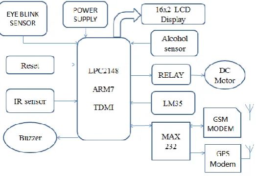
The design of the system starts with basic block diagram of the system which is shown in Fig 1. This system basically consists of accelerometer, alcohol sensor, IR sensor, temperature sensor, buzzer, relays, GPS and GSM interfaced with the microcontroller ARM7 (LPC2148). This system also has the theft control mechanism. The driver need to punch the password within 30 seconds while entering into car else buzzer will start buzzing and an SMS will be send to owner of the car.
Fig 1 :Block Diagram
Alarm Section: It is used in a system to indicate or to grab the attention regarding an emergency situation occurred. Buzzer act as a panic horn which indicates the need of instant attention as the condition goes haywire.
Alcohol Sensor: Alcohol sensor is used to detect weather the person have consumed the alcohol or not. The sensor which we have used is MQ3 sensor.
Eye Blink Sensor: Eye blink sensor is used to detect the rate of blinking of human eyes.
Microcontroller: Microcontroller is used to perform various function and operations is ARM7 i.e.LPC2148.
International Journal of Modern Trends in Engineering and Research (IJMTER)
Volume 2, Issue 10, [October– 2015] ISSN (Online):2349–9745 ; ISSN (Print):2393-8161
A. BLOCK DIAGRAM EXPLANATION
This system basically consists of accelerometer, alcohol sensor, IR sensor, temperature sensor, 4x3keypad, buzzer, relays, GPS and GSM interfaced with the microcontroller ARM7. This system will detect the alcohol consumption of the driver. As alcohol consumption is increasing within the youth so the accidents are increasing day by day. Driver consumes alcohol and then they do rash driving as they do not have control on themselves. Here we are designing a system which will detect the consumption of alcohol by the driver. Once detected, the vehicle will turn off the ignition and the buzzer will start. If driver start feeling drowsy then the accelerometer will detect and will turn off the ignition and the buzzer will start. By IR sensor interfaced the speed of the car will be kept under control. Once set the speed limit the driver will not be able to accelerate the car higher than the set speed. GPS interfaced with microcontroller will continuously transmit the location of car on GOOGLE map to the base station.
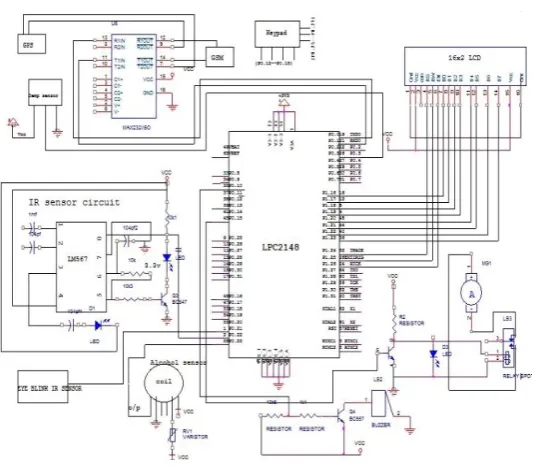
B. CIRCUIT DIAGRAM
Fig 2:Circuit diagram
C. Explanation of Circuit Diagrams
Here we are using the power supply which will be consisting of transformer of output 12 voltage and current of 750mA, which is then followed by the bridge rectifier circuitry of diodes (1N4007).At the output of this, we get pulsating DC voltage of 5.75 volts. This pulsating voltage is then applied to the filter circuitry consists of electrolytic capacitors. At this stage we get the pure DC voltage. The further part of the power supply circuit consist of the fixed voltage regulator IC 7805,which gives regulated output of 5 volts. This 5 volt supply is provided to the many components of the system such as LCD display, IR sensor, Alcohol sensor, temperature sensor, relays, MAX 232 IC, buzzer. The fixed regulator circuitry followed by variable voltage regulator which provides 3.2volt to the controller. Referring to Fig-3, which shows different components connected to the controller like LCD, buzzer, relay section, etc. There are some sensors connected like alcohol sensor, temperature sensor, accelerometer, IR sensor, etc. Also GPS & GSM are connected to controller through RS232.Crystal oscillator of 12 MHz is to connected to the pins XTAL 1 and 2.
International Journal of Modern Trends in Engineering and Research (IJMTER)
Volume 2, Issue 10, [October– 2015] ISSN (Online):2349–9745 ; ISSN (Print):2393-8161
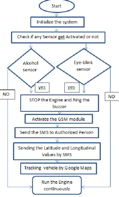
The flowchart of system is shown in Fig below which follows the different conditions, and systems reaction according to those conditions.
Fig 3 :Flow chart of process
Here we are also having the LM35 and also the IR sensor as inbuilt ,thus if any one of these gets activated then the buzzers will automatically starts ringing in the vehicle and hence trying to alert the person in the vehicle. Hence LM35 is used for the measuring of the temperature and the IR sensor is used for the detecting or finding an obstacle or an opposite vehicle.
VI. KEIL IDE & PROLOAD SOFTWARES
Keil ide is an Integrated Development Environment software that is in which is used for that we can develop our own code by using the predefined libraries which is written by using the c language and also by the open source codes which can be available as inbuilt. Thus we are going to develop the code for the each and every module by the Keil ide software that to be getting activated. Thus in this way we are going to activate the code for modules.
International Journal of Modern Trends in Engineering and Research (IJMTER)
Volume 2, Issue 10, [October– 2015] ISSN (Online):2349–9745 ; ISSN (Print):2393-8161
contains a power supply section in the board itself but in order to switch on that power supply, a source is required.
A. Software working and outputs
Here is the output for the keil ide software after the completion of the work on coding.
Fig 3.Keil output
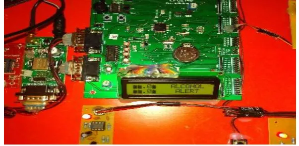
B. Results
Here is the result of the specified project i.e on the LCD display unit it is displaying that alcohol when he had consumed the alcohol.
International Journal of Modern Trends in Engineering and Research (IJMTER)
Volume 2, Issue 10, [October– 2015] ISSN (Online):2349–9745 ; ISSN (Print):2393-8161
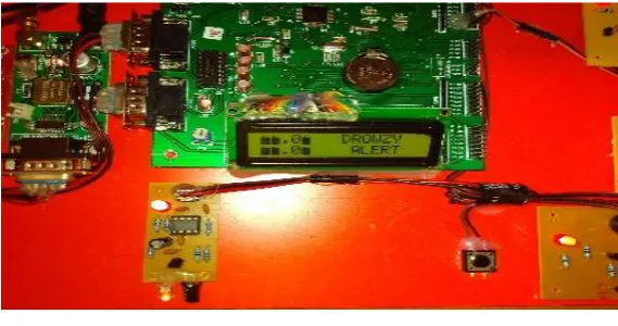
Here is the result of project i.e when the person is in Drowsy state.
Fig 5:Drowsy alert on LCD
VII. CONCLUSION
Using eye blink sensor and alcohol sensor this project is designed. By default the vehicle will be in running condition .During this time if the person closes the eyes automatically the vehicle will be in halt condition and even though if the person consumes alcohol, during this moment also the vehicle will stop and the updated message will be displayed on the 16x2 LCD and the message will be transmitted to the authorized person through GSM modem.
The system will sense and measure different parameters like alcohol concentration in human/driver body, head tilt position of driver, vehicle temperature, along with the GPS co-ordinates of the vehicle. The above measured parameter helps for security purpose of driver and to track the exact position of vehicle on the GOOGLE map.
REFERENCES
[1] www.ee.ryerson.ca/~phiscock/thesis/drowsy-detector/drowsy-detector.pdf
[2] www.ijcsit.com/docs/Volume%205/vol5issue03/ijcsit20140503346.pdf
[3] auto.howstuffworks.com/car-driving-safety/.../car-wake-you-up1.html
[4] Ueno H., Kanda, M. and Tsukino, M. “Development of Drowsiness Detection System”, IEEE Vehicle Navigation
and Information Systems Conference Proceedings,(1994), ppA1-3,15-20.
[5] Sean Enright, Electronics Engineering Student, 506-650-3611, May 26-2011, Alcohol Gas Detector “Breathalyzer”.
[6] Weirwille, W.W. (1994). “Overview of Research on Driver Drowsiness Definition and Driver Drowsiness Detection,” 14th International Technical Conference on Enhanced Safety of Vehicles, pp 23-26.
[7] Arpit Agarwal, “Driver Drowsiness Detection System”, portfolio of projects on human computer interaction,
December,2010.
[8] Paul Stephen Rau, National Highway Traffic Safety Administration, United States, Paper Number 05-0192 Drowsy Driver Detection and Warning System for Commercial Vehicle Drivers: Field Operational Test Design, Data Analyses and progress.
[9] Mallis, M.M., et al., Bio Behavioral Responses to Drowsy Driving Alarms and Alerting Stimuli, DOT HS 809 202,February 2000.
[10] Embedded system design book- Raj Kamal
[11] www.keil.com/arm/
[12] www.embedded arm.com
[13] Mikro Elektronika Easy ARM v7 user manual
[14] C Programming for Embedded Systems by Kirk Zurell