Volume-7 Issue-1
International Journal of Intellectual Advancements
and Research in Engineering Computations
Pelletizer automation using embedded system
Mr.R. Murugasami
1, S.Gowtham
2, A.K.Gowtham
2, S.G. Keerthana
2, T.Sankavi
21
Assistant
Professor, Department of Electronics and Communication Engineering
2UG Students, Department of Electronics and Communication Engineering
Nandha Engineering College (Autonomous), Erode-52, Tamil Nadu, India
ABSTRACT
An embedded system based design consists of a controller which is used to measure the current and voltage rating for the pelletizer. Based on the above parameters the load handled by the motor is calculated in a real time manner. The novelty of the proposed system is to set the predefined threshold value to the current drawn by the motor on both the ends such as, lower and upper limits. The current drawn by the motor exceeds the threshold value, the control unit in the proposed system automatically cut the power supply feed to the motor and protect the pelletizer from dangerous hazards. On the other hand, the motor current less than threshold value will automatically increase the load supplied to pelletizer by controlling the conveyor. The proposed system improve the work efficiency up to 50%, when compared with the traditional system and also the pelletizer activities are logged automatically round the clock. The proposed system is realized using PIC16F877 and CCS Compiler. The main objective of the paper is to increase the efficiency and ensure the flow of process of the industry uninterruptedly by control the load of the pelletizer using embedded system.
Keywords:
Adaptive control set, current ripple, Finite control set model predictive current control (FCS-MPCC), Permanent magnet synchronous motor (PMSM), Virtual voltage vectors.INTRODUCTION
As an important role in multiphase machines, five-phase permanent magnet synchronous motors (PMSMs) have received much attention during the past decade. Compared with three-phase PMSM, five-phase machines can achieve the advantages of lower torque ripples, better fault-tolerant capability and additional degrees of freedom regardless of slight control complexity. Therefore, five-phase PMSM is more appropriate for high performance conditions like electric vehicles (EVs) traction[1, 3, 10].SERVO control system with control loop principles plays a major role for automation development in industrial processes such as satellite tracking systems, conveyor systems, and electric vehicles etc .These servosystems generally employ speed sensors (encoders or resolvers) for
implemented, which can generate 4 × 2 × 2 × 2– and 4 × 2 × 2 × 2 × 2–scroll chaotic attractors, respectively, via switching control. Compared with the voltage operational-amplifier-based circuit, the proposed circuit has better performance in terms of circuit structure and bandwidth. Numerical simulations and experimental results are accordant [9]. This maglev system is highly influenced by the characteristics of the magnetic suspension control system, which produces a guidance force from the magnetic reluctance force between the rail and the EPMS, without any control device being required. However, this non-guidance-force control system is insufficient to prevent unintended lateral displacement caused by external forces. The characteristics of the EPMS have significant effects on the vertical levitation and lateral guidance force characteristics. The levitation height and the dynamics of the conveyor are controlled when the convey or stops. The static and dynamic characteristics of the levitated conveyor are improved by using pulse-field magnetization [8, 12]. The objective is to accurately estimate the expected work-in-process (WIP) on the conveyor, queueing delays due to congestion at intersection points, as well as assessing the conveyor system stability. A four-phase approach is used to estimate the WIP [11].
EXISTING SYSTEM
The power supply enters the MCB from the power line. Then the power is given to the contractor and then it directly enters the pelletizer.
If the load is increased the motor’s speed will be decreased and this will lead to motor jam without any alert as the existing system does not have LCD, relays and CT/PT. So this leads to decrease in the profit and needs more time and man power.
PROPOSED SYSTEM
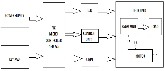
The proposed system design consists of a controller which is used to measure the current and voltage rating for the pelletizer. Based on the above parameters the load handled by the motor is calculated in a real time manner. The novelty of the proposed system is to set the predefined threshold value to the current drawn by the motor on both the ends such as, lower and upper limits. The current drawn by the motor exceeds the threshold value, the control unit in the proposed system automatically cut the power supply feed to the motor and protect the pelletizer from dangerous hazards. On the other hand, the motor current less than threshold value will automatically increase the load supplied to pelletizer by controlling the conveyor. The proposed system improve the work efficiency up to 50%, when compared with the traditional system and also the pelletizer activities are logged automatically round the clock. The proposed system is realized using PIC16F877 and CCS Compiler.The figure 3.1 shows the block diagram of the proposed system
LIQUID CRYSTAL DISPLAY (LCD)
LCD is a type of display used in digital watches and many portable computers. LCD displays utilize to sheets of polarizing material with a liquid crystal solution between them. An electric current passed through the liquid causes the crystals to align so that light cannot pass through them. The LCD has 14 pins and RB1 of the PIC microcontroller is connected to the RS pin of LCD and RB2 is connected to the RW,RB3 pin is connected to the E. RB4,RB5,RB6 and RB7 are connected to the D4,D5,D6 and D7 pins of the LCD respectively. These pins will get the data to be displayed. The LCD will display the current and voltage value according to the input range given from the keypad.
RELAY
A relay is defined as an electrically controlled device that opens and closes electrical contacts, or activates and deactivates operation of other devices in the same or another electrical circuit. Relay has five pins and the two pins are connected to the power supply. One of the pins is the common which is free. The normally open and the normally close pins of the relay will help in switching the ON/OFF conditions of the motor. The pin RC5 of the PIC is connected to the base of the transistor and the negative terminal of the relay is connected to the collector of the transistor [7].
CONTACTOR
Contactor relays are often used in control and regulating functions. They are used in large quantities for the indirect control of motors, valves, clutches and heating equipment. In addition to the simplicity which they offer in project engineering, panel building, commissioning and maintenance, the high level of safety which they afford is a major factor in their favor. Security The contactor relay contacts themselves constitute a considerable safety feature. By design and construction they ensure potential isolation between the actuating circuit and the operating circuit, in the de-energized state, between the contact input and output. All DIL contactor relays have double-break contacts. The Employers' liability insurance association demands that, for
control systems of power-driven metalwork presses, the contacts of contactors must be interlocked and opposing. Interlocking means that the contacts are mechanically connected to one another such that N/C contacts and N/O contacts can never be closed simultaneously. At the same time, it is necessary to ensure that the contact gaps are at least 0.5 mm over the lifespan, even when defective (e.g. when a contact is welded). The contactor relays DILER and DILA fulfil this requirement.
CT/PT
Current transformer is put in series with the line in which the current is to be measured. They are used to step down the current to such a level so that it can easily be measured by using an ammeter. Generally they are expressed as primary: secondary current ratio for e.g.: A 100:5 amp CT will have primary current of 100 Amp’s and secondary current of 5 Amp’s.Standard secondary rating of CT’s are either 5 or 1 Amp’sCommon application of CT available in market is “clamp meter”. If the secondary of Ct is open, it means that there will be no current flowing on secondary side and hence no mmf, whereas current will be flowing in the primary side and there will be mmf produced.To counter the mmf of primary, there will be no secondary mmf (because of no current on sec). Hence there will be large amount of mmf present in the current transformer [10].
nearby lines will trip due to earth fault which may trip the Power Generating Station.
The positive line of the three phase supply is given to the current transformer and the current consumed by the load is measured.
Potential transformers are also known as voltage transformers and they are basically step down transformers with extremely accurate turn’s ratio. Potential transformers step down the voltage of high magnitude to a lower voltage which can be measured with standard measuring instrument. These transformers have large number of primary turns and smaller number of secondary turns.A potential transformer is typically expressed in primary to secondary voltage ratio. For example, a 600:120 PT would mean the voltage across secondary is 120 volts when primary voltage is 600 volts.A VT is a "step-down transformer" that steps down voltage from a very high voltage level (200KV,) to a lower level (110V). Since, the power (P=VI) in a transformer (input and output) is same, the current rises to a very high level. Thus, a very high resistance is maintained at the secondary terminal to limit the current (which appears as open circuit)... Short circuiting the secondary would burn out the windings.Burden indicates apparent power related to potential transformer and / or of load connected to it. Burden rating of the transformer provide s maximum value of apparent power, which the the transformer can provide under specified conditions. Actual burden is the actual value of apparent power, that is being drawn by the load from the transformer output.
The voltage consumed by the load is measured using the potential transformer. According to the values of the current and the voltage the relay will be switched.
DC MOTOR
Almost every mechanical movement that we see around us is accomplished by an electric
motor. Electric machines are a means of converting energy. Motors take electrical energy and produce mechanical energy. Electric motors are used to power hundreds of devices we use in everyday life. Motors come in various sizes. Huge motors that can take loads of 1000’s of Horsepower are typically used in the industry. Some examples of large motor applications include elevators, electric trains, hoists, and heavy metal rolling mills. Examples of small motor applications include motors used in automobiles, robots, hand power tools and food blenders. Micro-machines are electric Micro-machines with parts the size of red blood cells, and find many applications in medicine. Electric motors are broadly classified into two different categories: DC (Direct Current) and AC (Alternating Current). Within these categories are numerous types, each offering unique abilities that suit them well for specific applications. In most cases, regardless of type, electric motors consist of a stator (stationary field) and a rotor (the rotating field or armature) and operate through the interaction of magnetic flux and electric current to produce rotational speed and torque. DC motors are distinguished by their ability to operate from direct current.
KEYPAD
CIRCUIT DIAGRAM AND CONNECTION
SOFTWARE SIMULATION
PROTEUS
Proteus is software for microprocessor simulation, schematic capture, and printed circuit board (PCB) design. It is developed by Lab center Electronics. PROTUES combines advanced schematic capture, mixed mode SPICE simulation, PCB layout and auto routing to make. a complete electronic design system. The PROTUES product range also includes our revolutionary VSM technology, which allows you to simulate micro-controller based design, complete with all the surrounding electronic.
CCS Compiler
CCS developed the first C Compiler for Microchip microcontrollers over 20 years ago and continues to provide software solutions to developers of embedded applications using PIC® MCU and PIC24/dsPIC® DSC devices. CCS compilers are easy to use and quick to learn. For the less experienced programmer, a detailed textbook explaining the C language and how it may be applied to PIC® microcontrollers.
Our compiler products include pro-level optimization, the largest library of built-in functions, powerful PIC® MCU specific pre-processor commands, and ready-to-run example programs to quickly jump-start any project. Our massive customer base provides us access to understanding our customer's requirements while developing advanced features with frequent releases and rare bugs.
CONCLUSION
The threshold value is got as an input and the motor is switched automatically when the current value exceeds the limit. The proposed system improves the work efficiency up to 50%, when compared with the traditional system and also the pelletizer activities are logged automatically round the clock. The proposed system is realized using PIC16F877 and CCS Compiler. The efficiency is increased and the flow of process of the industry is ensured by controlling the load of the pelletizer using PIC microcontroller.
REFERENCES
[2]. Suneel Kumar Kommuri, Me, Jagat Jyoti Rath, and Kalyana Chakravarthy Veluvolu.”Sliding Mode Based Observer-ControllerStructure for Fault-Resilient Control in DC servomotors”.CES transactions onindustrial electronics, 63(4), 2016.
[3]. F. Mendoza-Mondragón, V. M. Hernández- Guzmán, and J. Rodríguez-Reséndiz “Robust Speed Control of PermanentMagnet Synchronous Motors Using Two-Degrees-of-Freedom Control.” IEEE TRANSACTIONS ON INDUSTRIAL ELECTRONICS, 2, 2017, 2-5.
[4]. Weidong, Peixia Wang, Youyuan Ni, Jinping Wang, Lei Wang, and Yuming Liao .”Multi-mode Current Hysteresis Control for Brushless DC Motor in Motor and Generator State with Commutation Torque Ripple Reduction” 54, 2017.
[5]. Changliang Xia, Senior, Guokai Jiang, Wei Chen,Tingna Shi.“Switching-Gain Adaptation Current Control for Brushless DC Motors”. IEEE transactions on industrial electronics, 63(4), 2016.
[6]. J.W.Jung,V.Q.Leu,T.D.Do,E.K.Kim,andH.H.Choi,“AdaptivePID speed control design for permanent magnet synchronous motor drives,” IEEE Trans. Power Electron., 32(2), 2015, 900–908.
[7]. S.C. Carpiuc and C. Lazar, “Fast real-time constrained predictive current control in permanent magnet synchronous machine based automotive tractiondrives,” IEEETrans. Transport.Electrific.,1(4), 2015, 326–335.
[8]. Hyeon-Jae Shin1, Jang-Young Choi1, Kyung-Hun Jung2, Jong-Min Lee, and Chang-Hyun Kim. “Influence of Lateral-Impact Force on Electro-Permanent MagnetSuspension Conveyor with Inherent Guidance Force”. IEEE Transactions on Magnetics, 2, 2015, 1-4.
[9]. Ting Zuo, Kehui Sun, Xingxing Ai, and Huihai Wang“High-Order Grid Multiscroll Chaotic AttractorsGenerated by the Second-GenerationCurrent Conveyor Circuit”. IEEE transactions on circuits and systems, 61, 2014, 818-822.
[10]. C. Sheeba Joice, S. R. Paranjothi, and V. Jawahar Senthil Kumar. “Digital Control Strategy for Four Quadrant Operationof Three Phase BLDC Motor With Load Variations”. IEEE transactions on industrial informatics, 9(2), 2013, 974-982.
[11]. Dima Nazzal, Jesus A. Jimenez, Hector J. Carlo, Andrew L. Johnson, and Vernet Lasrado .”An Analytical Model for Conveyor-Based MaterialHandling System With Crossovers inSemiconductor Wafer Fabs”. IEEE transactions on semiconductor manufacturing, 23(3), 2010, 468-476.