Volume-5 Issue-2
International Journal of Intellectual Advancements
and Research in Engineering Computations
Design and optimization of a cutting parameters for composite
materials in drilling process
Sampath Kumar M 1, ArunKumar.J 2 , Balasubramani.D 2 , Gowtham.R 2 , Arumugam.M 2
1
Associate Professor ,2UG Students,
Department of Mechanical Engineering, Nandha Engineering College, Erode-52.
Tamil Nadu, India.
[email protected],[email protected],[email protected],
[email protected],[email protected]
Abstract - The cutting forces generated in metal cutting have a direct contact on heat generation, surface quality of work piece and accuracy of the work piece. A milling tool dynamometer that can measure static and dynamic cutting forces has been used for optimization. The orientation of octagonal rings and strain gauge locations has been determined to maximize sensitivity and to minimize cross sensitivity. The dynamometer is connected to a data acquisition system. Cutting force signals were captured and transformed into numerical form. It is processed using a data acquisition system consisting of necessary hardware and software running on a computer. The acquired results of machining tests performed at different cutting parameters represents that the dynamometer could be used to measure cutting forces. Though the dynamometer was developed primarily for drilling operations, it can be used to measure cutting forces in all machining operations such as turning, drilling, grinding, shaping etc.
Keywords: Dynamometer; Strain gauge; Data acquisition; Drilling
Introduction
Force measurement in metal cutting is essential as it is related to part design, power consumption, vibrations, part accuracy etc. It is the purpose of the measurement of cutting force to understand the cutting mechanism, machinability of the work piece and the process of chip formation and
tool wear. It is observed that the force values obtained by calculations, which contain some errors are compared to experimental measurements. Since the undeformed chip thickness and the direction of cutting speed vary at every moment, cutting process in drilling is geometrically complex. Considering such complexity, the cutting forces even in steady state conditions is affected by many parameters and the variation of cutting force with time has a peculiar characteristic .
The need for measurement of cutting forces component arises from many factors, but probably the important is the need for progress of tool wear .
If this can be obtained, it is possible to achieve tool wear monitoring in drilling based on force variation. The main reason for the cutting forces measurement is that it is a good indicator in detecting tool wear. It is known that during the cutting process, the cutting parameters such as cutting speed, Infeed , Thrust force and cross force represent a deviation from the calculated values.
The strain gauge produces a relation between the measured quantity and the strain on a certain spot on the spring element. In such cases, strain gauge type sensor which is used to obtain static force produces an output voltage proportional to elastic deformation.
The cutting force dynamometer must be manufactured at sufficient accuracy and high rigidity,and particularly suitable for dynamic loads. Indesigning dynamometer, some principles such as circular hole (8,10,16) have been used widely.
Design of the dynamometer The criterions for dynamometer design While designing a dynamometer, some criteria’s need to be given to following requirement, for its satisfactory working, accuracy of force measurements.
Sensitivity of transducing device
Simplified instrument design.
Rigidity of component of dynamometer
Accuracy of force measurement
Minimum cross sensitivity
Frequency of the dynamometer to be much higher a operating frequency
Sliding component to be minimum.
Minimum environmental effect
In addition, the structure of the dynamometer has to meet strict requirements concerning the natural frequency and wide frequency response and cross-sensitivity. The ring elements must be machined identically and symmetrically to prevent cross sensitivity and they should have required surface quality and high measurement of tolerance.
Fig 1.octogonal ring
The mechanical properties of rings must be determined experimentally. A dynamometer consists of an important ring element. The rigidity, high
natural frequency, corrosion resistance and high heat conductivity factors were considered while selecting the ring materials. Also, deformation under the load should conform to that of strain gauges. In this project, steel which meets the above requirements, was selected as the ring material. The dimensions for the ring element are width (b) = 28 mm; radius (r) = 30 mm; thickness (t) = 8 mm.
Experimental Set Up
Machine Tool- Radial Drilling Machine at Nandha Engineering college workshop.The dynamometer designed has three force components capable of measuring cutting forces during drilling operations. A computer is used for data acquisition. The schematic representation of the cutting force measurement system is capable of measuring feed force (Ff), Thrust force (Ft), and the main cutting force (Fc) that occurs during drilling
Operations is shown in the figure. The dynamometer consists of four octagonal rings on which strain gauges have been mounted and necessary connections are provided to form measuring the Wheatstone bridges.
Fig 2 Experimental setup
Experimental Orientation of the strain gauges on the ring elements We are using four types of materials like Nickel, Aluminium, agraligue and mild steel. These are the materials are named by A,B,C and D.These materials are used to calculate the Thrust force, cross force and Infeed by using milling tool dynamo meter.The strain gauges are used seperately on the same location for the torque to prevent any interference of Wheatstone bridge signals in real-time operation dedicated for force and torque. Thesignals from strain gauges are used to form the Wheatstone bridge which to be used for torque in operations like drilling, tapping, etc.
Fig 3.Agraligue
Fig 4.Aluminium
Fig 5. Mild steel
Fig 6. Nickel
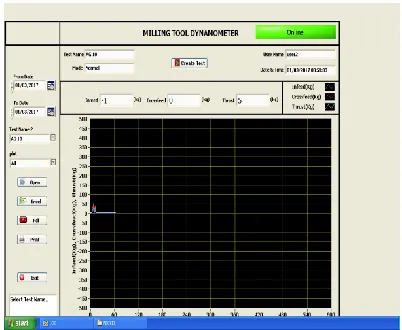
Fig 7. Testing report
Testing of the Dynamometer-
Linearity Test- While calibrating, the loads were applied in each direction equally one at a time and that the dynamometer shows linear variation in the strain developed is obtained. The calibration curve for each component shows the behavior of the dynamometer.
Cross sensitivity Test- While calibrating, it was observed that the effect of other components on the loaded component is minimum. The calibration curve for each component shows the effect of cross sensitivity on each component. It has been observed that the cross sensitivity is around 8 to 14 %.
ACKNOWLEDGEMENTS
The author takes this opportunity to thank the ask Engineers, Intellectual Engineers, workshop atNandha Engineering college, Ambav fortheir invaluable contribution in completing the project work.
REFERENCES
[1] J.D. Kim, D.S. Kim (1997), Development of a combined-type tool dynamometer with a piezoaccelerometer for an ultra-precision lathe, Journal of Materials Processing Technology (71) 360–366.
[2] S.K. Birla (1980), Sensors for adaptive control and machine diagnostics, Proceedings of the Machine Tool Task Force Conference (4) 7–12.
[3]. Ihsan Korkut, “a dynamometer design and its construction for milling operation” International journal for machine tool and design, 2003, published by science direct
[4]. Suleyman Yaldız, Faruk Unsacar ,“design development and testing of a four-component drilling dynamometer for the measurement of cutting force and torque” International journal for machine tool and design,2006, published by science direct
[6]Liu D, Tang Y, Cong W.L.; 2012. A review of mechanical drilling for composite laminates, Composite Structures, 94(4): 1265-1279.
[7]Mohan N.S, Kulkarni S.M, Ramachandra A.; 2007.
[8]Rajmohan T, Palanikumar K.; 2013. Application of the central composite design in optimization of machining parameters in drilling hybrid metal matrix composites Measurement, 46(4): 1470-1481.
[9]Sardinas R.Q, Reis P, Davim J. P.; 2006.Multi-objective optimization of cutting parameters for drilling laminatecomposite materials by using genetic algorithms, CompositesScience and Technology, 66(15): 3083-3088