3122
The Use Of Locally Sourced Materials In The
Design And Analysis Of A Portable Cassava
Peeling Machine
Okoronkwo C. A, Ezurike B.O, Adjogbe A.S, Oguoma O.NAbstract: The presented paper is on the design and fabrication of a portable cassava peeler with objectives to reduce labor input involved in cassava processing and provide affordability for commercial production of the machine using durable and locally sourced materials. The paper highlights previous literature on the research papers, describing the new design machine and its principles of operation, the design calculation deliverables made for accurate construction phases and machine performance evaluation after testing was carried out. From result obtained, performance test revealed that 9 kg of cassava tuber was peeled per minute, and the weight of cassava peels only accounted for 9.7% of the total average weight of tubers fed into the machine. The machine was able to remove about 89.42% of the peels resulting to a capacity of 9.36Kg/min and an overall efficiency of 91.72% was obtained.
Index Terms: Cassava tuber, Cassava peeler, Peeler Disc, Electric Motor, Belt-Pulley.
————————————————————
1.
INTRODUCTION
The processing of cassava involves the harvesting the cassava tubers from the farm. Thereafter, the tuber is then peeled and washed before the cassava can be processed into a variety of products like floor, chips, garri etc. The peeling of the Cassava tuber is manually done especially in the rural areas because of lack of machines that can feel the tubers without wasting the useful product. The cassava tuber is bewildered with variety of shapes and sizes making it difficult to peel [2]. Several efforts have been made to develop machines that can adequately peel the tubers in Nigeria. Most often, these machines have failed to peel the cassava effectively resulting in the abandonment of such machines. On the other hand, some that were successfully designed were encumbered with low performance [3]. However, the manual peeling of cassava tuber with knife has been very stressful with low production rate as low as 350 kg/day of 8 hour/person [8]. In view of the above, there is need for necessary technological innovation in cassava processing to improve output quality and reduce production cost. Several efforts have been made at improving cassava peeling in recent time. Some of the innovative machines developed include: knife-edged automated cassava peeling machine - type1, Abrasive-tooled cassava peeling machine and Knife edged automated cassava peeling machine-type 2, The model II cassava peeler prototype etc. The model II cassava peeler prototype, as reported by [3], possesses bolls of metals as abrasive material. The efficiency of the machine was as low as 64%. On the other hand, a Single and double gang models A and B cassava peeling machine, was developed at Federal University of Technology Akure (FUTA). This machine was found to be more effective but had a major deficiency in that it could not peel cassava tuber with small diameter [1]. The deficiency in the found in the Single and double gang models A and B cassava peeling machine, led to the development of the FUTA cassava peeling machine (self-fed), model C, this machine was an improved design with capacity of 10 tons per day [4], [7]. Its operation was tedious and the splitting of useful flesh of the cassava tuber was high. In addition, the system was manually operated. Having examined the knowledge gap in the entire previous models of cassava peeling, the present design was adopted to peel cassava
more efficiently and effectively. This project is targeted at the design and fabrication of an electrically operated cassava peeling and washing machine. Okoronkwo C.A: Department of Mechanical/ Mechatronics Engineering, Federal University of Technology, OwerriEzurike B.O: Department of Mechanical/ Mechatronics Engineering, Alex Ekwueme Federal University, Ndufu-AlikeAdjogbe S.A: Project and Program Division, Niger Delta Development Commission, Port Harcourt, NigeriaOguoma O.N: Department of Mechanical Engineering, Federal University of Technology, Owerri
2.
DESCRIPTION OF MACHINE
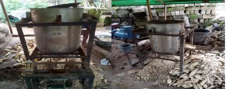
The machine as shown in figure 1 is consists of a frame made from high carbon steel (mild steel), which supports its entire components. The peeling drum is made of stainless steel metal sheet with zinc abrasive material lined around it. The fresh cassava is poured into peeling drum manually at a regulated quantity as shown in figure 1. The peeling unit was fastened unto the machine frame by screwing it firmly on to the machine frame; the peeling drum was mounted on a shaft connected to an electric motor.
Figure 1. Showing the cassava peeling machine
3123 surface and then get peeled. The peeled cassava tubers
are collected at the discharge chute. The water and the peeled epicarp will be collected in a tray located below the peeling drum but in this case due to lack of adequate water the water discharging unit was deactivated.
Fig 2a: Diagram of a Cassava Peeling Machine
Fig 2b: Exploded Diagram of the Cassava Peeling Machine
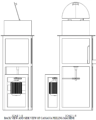
Fig 2c: Back and Side Views of Machine
Fig 2d: Dimensional Diagram of the Machine
3.
METHODOLOGY
3124 not to introduce so many cassava tubers at a time.
Excessive cassava creates a grinding effect in that the heavy weight of cassava on top presses the ones below on the abrasive spinning disc thereby eating up the cassava tubers.
Design Calculation and Analysis
Selection of electric motor
An electric motor of the following specification on the name plate was selected.
Power P 0.75kw (1hp) Rotational speed, N 1400 rev/min Phase Single
Frequency 50Hz
Pulley design calculation
The diameter of the pulley required was obtained from velocity ratio relationship
Velocity ratio (V.R) =
= (1)
Where = diameter of the driving pulley (m) = Speed of the driver (electric motor) in rpm = Diameter of the driven pulley (m) speed = Speed of the driven pulley (rpm)
The speed of the driven pulley is equal to the average rotational speed of the peeler plate disc necessary to achieve efficient operation.
Power required to drive the machine using an electric motor of 1hp.
P = 1hp = 0.746kw Therefore, P = 746Watt
Volume of peeler disc = volume of stainless solid disc + zinc abrasive perforated disc.
Vp = Vps + Vpz (2)
Vpz1 = x x 2 Vpz1 =
Vpz = x x 0.0016
Actual volume of perforated zinc peeler disc,Vpz Vpz = Vpz1 – Vpz2
Vpz = (2.513 x ) – (2.011 x )
Volume of the peeler disc = Vps + Vpz Vp = (3.77x ) + (2.51 x )
Note: Mass of peeler disc, Mp = 4.7Kg (measured) Force due to centrifugal action of peeler disc
Fc = (3)
V = = (4)
Where V = velocity of the peeler disc t
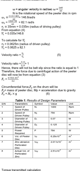
ω = angular velocity in rad/sec ω =
N is the rotational speed of the peeler disc in rpm = 146.6rad/s
= = 82.1 rad/s
35mm = 0.035m (radius of driving pulley) From equation (4)
= 0.035x146.6
To calculate for
= 0.0625m (radius of driven pulley) = 0.0625 x 82.1
Velocity ratio = (5)
Velocity ratio = = 1
Hence, there will not be belt slip since the ratio is equal to 1 Therefore, the force due to centrifugal action of the peeler disc will now be from equation (3)
=
Circumferential force, on the drum will be
= mass of peeler disc, Mp × acceleration due to gravity
= g (6)
Table 1: Results of Design Parameters
S/N Parameters Symbol Value Unit 1 Speed of
Driver Pulley
N1 1400 Rpm
2 Speed of Driven Pulley
N2 784 Rpm
3 Diameter of Driving Pulley
D1 0.07 M
4 Diameter of Driven Pulley
D2 0.125 m
5 Power
Required
P 764 W
6 Vol. of Peeler Disc
VP 6.28x10⁻⁴ m3
7 Zinc abrasive Perforated Disc
VPZ 2.011x10 -7
m3
8 Actual Vol. of Perforated Zinc
VPZ 2.51x10
-4
m3
Torque transmitted calculation
Torque exerted on the driven pulley and driving pulley can be calculated from
P = T × ω (7)
Ta = P/ =
Ta = 5.09Nm (Torque exerted on the driving pulley) Tb = p/ (Torque exerted on the driven pulley)
Total torque transmitted, T = Fc x r (8)
Where F is the force due to centrifugal action of the peeler disc
3125
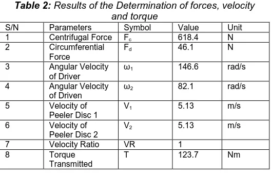
Table 2: Results of the Determination of forces, velocity and torque
S/N Parameters Symbol Value Unit
1 Centrifugal Force Fc 618.4 N
2 Circumferential Force
Fd 46.1 N
3 Angular Velocity of Driver
ω1 146.6 rad/s
4 Angular Velocity of Driven
ω2 82.1 rad/s
5 Velocity of Peeler Disc 1
V1 5.13 m/s
6 Velocity of Peeler Disc 2
V2 5.13 m/s
7 Velocity Ratio VR 1
8 Torque
Transmitted
T 123.7 Nm
Belt Design Analysis and Calculation
Fig 3: Belt design
= angle of contact or wrap
r2 and r1 = radius of the larger and smaller pulley
x = distance between the centers of the two pulleys O1 and O2
L = Total length of the belt From the above geometry
Sin = (9)
r2 = 0.0625m andr1 = 0.035m x = 407mm = 0.407m (measured)
Making the subject of formula, we have
= Sin -1
(
= sin-1 = 1.38rad
From [5], the length of a belt drive is given as L=π ( (in terms of pulley radii)
(10)
Table 3: Results of Design of Shaft
S/N Parameter Symbol Value Unit
1 Torque from Driving Pulley
Ta 5.09 Nm
2 Torque from Driven Pulley
Tb 9.09 Nm
3 Diameter of Shaft to be selected
d 9.39 mm
4 Distance from neutral axis
r 0.00517 m
5 Angle of twist θ 0.02 rad
6 Length of belt drive
L 1.12 m
Determination of Angle of contact
From [5] the expression for angle of contact is given as
= (180-2 ) (rad) (11)
Determination of Power transmitted by belt The power transmitted by the belt is given as P = (T1 – T2) V in Watts (W) (12)
Where,
T1 = Tension in the tight side of the belt T2 = Tension in the slack side of the belt V = Velocity of the belt (m/s)
(T1 – T2) is the effective turning (driving) force at the circumference of the driving pulley
T1 – T2 = P/V T1 – T2 =
Torque exerted on the driving pulley is Ta = (T1 – T2) r1
Torque exerted on the driven pulley is Tb = (T1 – T2) r2
Centrifugal Tension (Tc) (13) Tc = MV
2
Since the linear velocity of the belt V = 5.13m/s < 10mls, centrifugal tension has no effect on the power transmitted and it is neglected.
Table 4: Results of Angle of Contact, tension, Power transmitted by belt etc
S/N Parameter Symbol Value Unit
1 Angle of Contact
θ 3.09 rad
2 Power
Transmitted
P 745.9 W
3 Tension in tight belt
T1 438.3 N
4 Tension in slack belt
T2 292.9 N
5 Max. tension in belt
Tmax= T1 438.3 N
6 Max. stress on belt
σm 4.21 Mpa
7 Mass of belt M 0.119 Kg
8 Width of Pulley B 16.25 mm
Hence, from the ratio of driving tension given as 2.3 log (
) = µθ (14) It reduces to
2.3 log * + = µθ (Tc is neglected)
Where µ is the coefficient of friction between the rubber belt and the pulley
θ is the angle of contact or lap
Coefficient of friction between belt and pulley
3126 Pulley material
Cast iron, steel
Belt material Dry Wet Greasy Wood Compressed paper Leather face Rubber face 1 Leather Oak
tanned
0.25 0.2 0.15 0.3 0.33 0.38 0.40
2 Leather chrome tanned
0.35 0.32 0.22 0.4 0.45 0.48 0.50
3 Canvass – stitched
0.20 0.15 0.12 0.23 0.25 0.27 0.30
4 Cotton woven 0.22 0.15 0.12 0.25 0.28 0.27 0.30
5 Rubber 0.30 0.18 - 0.32 0.35 0.40 0.42
6 Balata 0.32 0.20 - 0.35 0.38 0.40 0.42
The coefficient of friction µ = 0.30 was selected from the table 5 above [5].
Log ( ) = T1 = T2eµθ/2.3
Substituting T1 into equation (1), we get
T2eµθ/2.3 – T2 = P/V
T2 (eµθ/2.3 – 1) = 145.4 (15)
The tension on the slack side, T2 becomes T2 =
T2 = (
)
From equation (1) T1 = 145.4+T2
From equation (12), power transmitted by belt will be P = (T1 – T2) V
Determination of Maximum tension in the belt, The maximum tension in the belt is equal to the tension in the tight side of the belt since centrifugal tension, Tc was neglected.
Therefore, Tmax= T1 = 438.3N
The maximum safe stress on the belt is expressed as = (MPa) (16)
The belt dimensions for the pulley selected and the power rating for V – belts according to IS: 2494 – 1974 is given as: Belt thickness t = 8mm = 0.008m
Belt width, b = 13mm = 0.013m =
Mass of the belt per unit length is given by the expression
M = ρ x A (17)
Where ρ= density of rubber belt (1140kg/m3 ) [5]. A = cross sectional area of the belt (m2)
Width of the pulley, B
B = 1.25b (18)
B = 1.25×13
Shaft design calculation
When the shaft of the driven pulley which is rotating the peeler disc, is subjected to twisting moment only.
For a shaft subjected to twisting moment only, the diameter of the shaft can be obtained using the torsion equation given in the below equation
T = x x d3 (19)
Where T = twisting moment acting on the shaft = torsional shear stress
d = diameter of the shaft
For steel shaft without allowance for keyway the maximum permissible shear stress,
= 56MPa = 56N/mm2
Torque exerted on the driven pulley Tb = (T1 – T2) r2 (20)
Hence, 9.09 = x 56 x106 x d3
d = √
d = 0.00939m (diameter of the shaft to be selected) from the relation for torsional equation shown below
= = (21)
Where j = polar moment of inertia of the shaft about the axis of rotation
J = (22)
G = modulus of rigidity (G = 82.5GPa) of the shaft L = length of the shaft = 220mm = 0.22m
r = distance from neutral axis to the outermost fiber = d/2 Using =
The angle of twist of the shaft can be calculated thus: =
=
3127 Analysis of when the shaft is subjected to bending moment
only
For a shaft subjected to bending moment only, the diameter of the shaft can be obtained using the bending equation given below
= (23)
Where M= bending moment
I = Moment of inertia of cross sectional area of the shaft about the axis of rotation
= bending stress
y = distance from neutral axis to the outer most fiber For a round solid shaft, moment of inertia is I = × and y
=
Substituting I and y into the above bending equation, we have that
M = × ×
The maximum permissible working stress in the tension or compression is taken as
= 112MPa for shafts without allowance for keyways [5] The load distribution across the shaft is shown below: Assuming the tension to be vertical
Maximum allowable shear stress of 56Mpa (shafts should withstand allowable stress for keyways)
Fig 4: Load distribution across the peeler disc shaft
Mass on Pulley selected is 1.4Kg
Weight of pulley = Mg (24)
Weight of pulley = 1.4 × 9.81 Weight of pulley = 13.7N
Fig 5: Force analysis of the pulley Neglecting the weight of the shaft
Total downward force acting on the pulley W2 W2 = 438.3 + 292.9 + 13.7 = 744.6N
For the peeler disc,
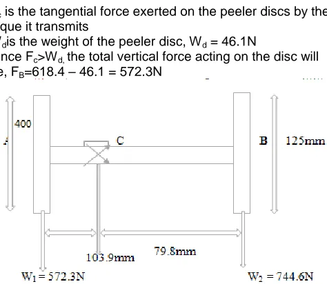
Fig 6: Force analysis of the peeler disc
Fc is the tangential force exerted on the peeler discs by the toque it transmits
Wdis the weight of the peeler disc, Wd = 46.1N
Since Fc>Wd, the total vertical force acting on the disc will be, FB=618.4 – 46.1 = 572.3N
Fig 7: Line dimension of peeler disc, bearing and pulley
3128 Therefore, Bending moment M = W2 × L
M= 744.6 × 79.9 M= 59.49 × 10³ N-m M =
× ×
= √
= √
d = 17.6mm (Diameter of the shaft to be selected) When the shaft is subjected to bending and twisting moment
When the shaft is subjected to both bending and twisting moment, the diameter of the shaft is determined using the maximum shear stress theory used for ductile material such as mild steel [5]
From maximum shear stress theory, maximum shear stress of the shaft is given as
= ×√ (25)
Substituting the values of and , we have that
× × = √ = √ =
× ×
Where = equivalent twisting moment M= bending moment
T= Twisting moment
During the design of the line shaft, combined shock and fatigue factors were taken into consideration
Assuming a shock factor and fatigue factor for both bending and twisting as =2 and = 1.5
=√
=√ = 118.98 × N-mm
Substituting = × ×
d = √
d= 22.10mm.
From the standard diameters of transmission shaft [5], a shaft diameter of 22mm was selected for the shaft in this design
Analysis of Results Performance Evaluation
Performance evaluation was carried out on newly harvested cassava tuber, in which regular sizes were selected and fed into the machine that was switched on. The operation procedure was timed from when the cassava tuber was fed-in to the collection at discharged chute of the peeled cassava tuber.
Assumptions made during evaluation
There is a need to make simplifying assumptions in order to reduce the number of parameters involved to manageable level thereby reducing the complexity of the model. The assumptions include;
Cassava tubers are fairly cylindrical (the tubers are cut into sizes in order to eliminate pronounced bends)
Tuber weight is between 0.2 kg to 0.4 kg with tuber diameter ranging between 30mm to 60mm Tuber length is presented between 70mm to
90mm long.
The machine was evaluated for peeling efficiency, machine throughput capacity, percentage weight of peels and percentage weight of peeled cassava.
Peeling efficiency (P.E)
P.E= (26)
Where
Machine throughput capacity (MTC) MTC= ×100 (27)
Percentage weight of peels (% )
% = (28)
Percentage weight of peeled cassava (% W.P) % W.P= (29)
Where
Weight of peel removed by machine (kg) Total weight of peels (kg)
Where
Weight of cassava fed into the machine (Weight of unpeeled cassava tubers) in kg
Weight of completely peeled cassava tubers (kg) Weight of peel removed by hand after machine peeling (kg)
Total time taken for peeling (min) Discussion of Results
3129
Table 6: Result of trial runs performed at constant speed of 784 rev/min of the peeling shaft
Trial runs
Speed rpm
Duration of peeling (secs)
(Kg) (Kg) (Kg) (Kg) (Kg)
MTC Kg/s
W.P %
P.E
% %
1 784 20.17 0.27 0.29 3.10 2.82 0.02 0.154 90.97 93.10 9.35 2 784 20.02 0.27 0.28 3.00 2.69 0.01 0.150 89.67 96.43 9.33 3 784 20.68 0.30 0.34 3.20 2.81 0.04 0.155 87.83 88.24 10.63 4 784 19.86 0.26 0.29 3.10 2.77 0.03 0.156 89.35 89.66 9.35 5 784 21.20 0.31 0.34 3.45 3.08 0.03 0.163 89.28 91.18 9.86
Average 0.156 89.42 91.72 9.70
From the Table 6,
Machine throughput capacity, M.T.C= 0.156 Kg/s M.T.C =
M.T.C =9.36 Kg/min
Average Percentage weight of peeled cassava (%W.P)
%W.P = %W.P= 89.42%
Average Peeling Efficiency, P.E P.E= P.E= 91.72%
Average Percentage weight of peels (% )
% = % =9.70%
From the result above, the weight of cassava peels only accounted for 9.7% of the total average weight of tubers fed into the machine. The machine was able to remove about 89.42% of the peels, with machine capacity of 9.36Kg/min. The cassava peeling machine having an average peeling efficiency of 91.72% indicates that it is very effective.
4.
CONCLUSION
The design and fabrication of a cassava peeling machine has been successfully carried out and it was found to be effective and efficient. The cassava peeling machine with a unique mode of operation of peeling was designed with a power requirement of 1.0HP. Performance evaluation carried out, showed that the throughput capacity of 9.36 kg/min at machine speed of 784 rpm was achieved. Peeling efficiency of 91.72% was also obtained, while the overall weight of peels is 9.70%. It has been designed for ease of operation and maintenance without special training to meet the increasing demand for an affordable cassava peeling machine, although one particular problem that hindered the efficiency of the machine is the irregular shapes of the tuber which was taken care of by resizing the tubers to an accepted length.
ACKNOWLEDGEMENT
We sincerely appreciate everyone who participated in this research especially from FUTO, FUNAI and NDDC.
REFERENCES
[1]. Agbetoye, ―Improving the Technology of Cassava Harvesting and Processing Mechanization for food
security in Nigeria‖. Paper presented at the International Conference on Science and Technology, Held at the Federal University of Technology, Akure, Ondo State, Nigeria, 2005,196 – 204. (2005)
[2]. G.O. Ezekwe ―A feature for achieving a constant depth of peel in the Mechanical peeling of Cassava‖. Nigeria Journal of Engineering, 1(3), 174-181. (1976)
[3]. E.U. Odigboh. Prototype Machine for Small, Medium scale Harvesting and Processing of Cassava Production. Int. Symposium on Mechanization and Harvesting and Subsequent Processing of Agricultural products in Tropical Africa and the Manufacturing of relevant implements. Yaoundé, CIGRIII.323-338. (1985)
[4]. O.J Olunkunle, Ogunlowo A.S and Sanni L. ―The search for an Effective cassava peeler‖, The West Indian journal of Engineering, Vol.32 pp 42-47. (2010) [5]. R. S. Khurmi and Gupta J. K. Machine Design, 4th
Edition, Eurasia Publishing House. New Delhi: S. Chand and Company Ltd (2005)
[6]. R.S. Khurmi and Gupta J.K. Shaft, V-belt and Rope Drives: A Textbook of Machine Design. 13thEdn., S. Chand and Company Ltd., New Delhi, pp: 681. (2004 [7]. O.J Olunkunle and Jimoh M.O. ―Comparative Analysis
and Performance Evaluation of Three Cassava Peeling Machine‖. International Research Journal of Engineering Science, Technology and Innovation, vol.1(4), pp94-102.(2012)