Heat and mass transfer in a vertical channel under heat-gravitational
convection conditions
Michail Petrichenko1, Darya Nemova1, Elisaveta Reich1,,a, Svetlana Subbotina1 and Faina Khayrutdinova1
1
St. Petersburg State Polytechnical University, 195251 St. Petersburg, Russian Federation
Abstract. Heat-gravitational motion of an air flow in a vertical channel with one-sided heating in an area with low Reynolds number is stated in Boussinesq approximation. Hydraulic variables field in a heat-gravitational motion is modeled with the application of ANSYS-FLUENT. It is converted to average velocity and temperature values in a cross section of the channel. The value of an average velocity is determined by rate of heat supply in a barotropic flow with a polytropic coefficient n<k. An average velocity versus flow resistance characteristic is ascertained. Largest extremum of channel flow coefficient is less than 0,707. Physical modelling of the flow is performed on a variable geometry unit. Calculation and experimental data established that an average velocity reaches a maximum in a ventilated vertical channel with free air access and in the absence of gaps. In a channel with closed air access inleakage of the cold air through gaps on an unheated side leads to decrease in an average speed at least twice in comparison to channel with free air access.
1 Introduction
Heat-gravitational convection occurs in different technical devices and natural phenomena (from the heat engine to meteorology and ocean dynamics). It also explains the movement of an air in a vertical heated channel.
JV Boussinesq has formulated the conditions for simplifying motion equation of a viscous incompressible fluid that is known as the Boussinesq approximation. He formulated key insight of the theory, allowing writing motion equation of heat-gravitational motion of viscous fluid in a gravitational field.
Initial interest in the natural convection evident in the work of physicists. Physical bases of natural convection was investigated by H. Lorentz, J. Boussinesq, E. Eckert, V. Zhukovsky and etc.
E. Eckert in his work in 1929 by expansion in power series integrates the equations of motion and energy. He obtained for the first time criterial formula for the transfer coefficients on a plate under natural convection in a semi-infinite space.
The issues of heat-gravitational convection in engineering structures are viewed in reports [1-29].
N. Mingotti, T. Chenvidyakarn, A. Woods in their paper described buoyancy flow in ventilated facades. They suggested model, that hydraulically describes flow mechanics. Thus, it became possible to estimate an influence of design feature of the façade on air flow in construction. [1].
Portuguese scientists F.M. Silva, G. Gomes, M. Rodrigues basing on in-situ testing of ventilated facades developed a mathematical model that made possible to predict heat-gravitational flow in these constructions [2].
C. Popa, D. Ospira, S. Fohannoa, C. Chereches made a numerical simulation of buoyancy flow in ventilated facades. They took in account Rayleigh number and influence of boundary layer in their paper [3].
The aim of this study is to determine discharge characteristics of heated vertical channels in a low-Reynoldsless than area. Accomplish this aim such challenges should be figured out:
1. To perform theoretical estimate of flow characteristics in conditions of heat-gravitational convection (average velocity, heat transfer rate, pressure loss, average temperature of the flow) and to evaluate rate of heat transfer, temperature and moisture in conditions of heat-gravitational convection.
2. To perform numerical simulation of plain flow in conditions of heat-gravitational convection in ANSYS Fluent.
3. To perform physical simulation of heat-gravitational convection in different types of vertical channels.
2 Deriving of calculation dependences
Fundamentally there is an Eckert model of heat-gravitational motion. It consists of equations that state motion, energy and continuity equations:
C
θ ν g y u y u u z u
u z z
y z z + ∂ ∂ = ∂ ∂ + ∂ ∂ 2 2
2 2 y y u z
uz y
∂ ∂ = ∂ ∂ + ∂ ∂ θ σ ν θ θ (1)
=0 ∂ ∂ + ∂ ∂ y u z
uz y
where, uz,y – longitudinal and transverse velocity
components, θ - non-dimensional temperature head,
θ:=(T-Tc)/(Th-Tc), Th, Tc – temperatures of heated surface and cold air, ν - coefficient of kinematic viscosity of an air, σ - Prandtl number. This set of equations is necessary and opportune in conditions of heat-gravitational convection due to minimum of allowances and relying on basic mechanics lows.
In Eckert model the fulfillment of conditions of hydrostatic pressure distribution in vertical direction is essential:(Boussinesq approximation). In other words, force of the flow pressure in heat-gravitational motion is counterbalanced by gravity force. The one volume force is – ascending force with mass density gθ. Set of equations is supplemented by boundary conditions, that state no-slip condition on the surface and continuity of non-dimensional temperature head on air-surface boundary. Eckert model is correct for laminar (low-Reynolds) flow. In conditions of real vertical ventilated layer thermal Grashof number:
Grh,θ,=gh3/ν2*(Th-Tc)/Th (2)
where h – width of the channel, is less than 105…107, that is in accord with laminar flow.
As usual hydraulic model, Eckert model determines velocity and temperature head distributions in flow space. In hydromechanics, local velocity and temperature head distributions are substituted with average velocities and temperature heads in cross-section. Therefore averaging across the width of boundary layer or channel allows to calculate hydraulic flow characteristics – average velocity and temperature head. In addition, with the knowledge of velocity and temperature head gradients on the side of the channel it is possible to calculate coefficient of hydraulic friction number and heat-transfer coefficient.
Boussinesq approximation is applied to heat-gravitational motion of viscous liquid. Basic allowances, composing Boussinesq model form the following set of conditions: liquid is a perfect gas, p=RʌT; motion is barotropic (polytropic index n), static pressure p is in accord with equilibrium condition. Barotropic condition replaces differential energy equation in Eckert system.
Average velocity of the flow in vertical channel is determined.
When heat supply to air flow n≤k. Therefore:
Technical works of expansion in absence of external heat-exchange is less than technical works of polytropic expansion lT,n, n≤k.
Excess of technical work is expended in mass motion of an air in the channel. Consequently:
c c RT gL : k n RT
v=ϕΛ 1−1 , = (3)
Using basic allowances it can be showed that:
gL T T T gL v h c h r 2 2 1 1 − = + − = ϕ
ζθ (4)
In formula (3), (4): ϕ - velocity coefficient, L – height of the channel.
The following functions were deduced: 1. For an average velocity:
gL T T v h c 2 1−
=
ϕ
(5)where: ζ λ ϕ + + = h L 1 1
: - velocity coefficient
λ
- coefficient of hydraulic friction,ζ
- local head loss coefficent, 2. For heat-transfer rate:4 2
3
N σ
κ
δ =
=h (6)
where: 4 2 4 g z
ν
δ
= - width of the «boundary layer of force ofthe flow pressure»
v – coefficient of hydraulic friction,
z – vertical distance from the lower bound of ventilated layer;
h – heat transfer coefficient,
κ– air thermal conductivity,
σ – Prandtl number. For an air σ=0,707. 3. For head loss:
2 2
2g
ϕ
V
hr = (7)
where: ζ λ ϕ + + = h L 1 1
: - velocity coefficient
λ
- coefficient of hydraulic friction,ζ
- local head loss coefficient;4. For an average temperature of the flow:
c c
h
m e T
T T
T = − (1− − ⋅ )+
3
43
4
ζ (8)
where:
Th - temperature of heated surface Tc- temperature of the cold surface
δ
ζ = y - nondimensional coordinate (transverse
coordinate to width of the boundary layer ratio).
3
Numerical simulation
solved. There are 3 equations and 3 unknown quantities in all(2 velocity components and temperature). Energy equation can be substitute with the condition of barotropy of the motion. It is a determined system.
In the field of varying of calculated functions there are some difficulties in calculation of distributions and their gradients. Original set of equations is written as averaging system, there are different translation models for coefficients of stress matrix.
Numerical simulation consists on two parts: - selection and testing of model constants; - problem solving for heat-gravitational motion.
3.1 Selection and testing of model constants
The model has been selected from a three models: k-ε standart, Girimadji, SST k-ω - the model of kinetic energy - vorticity of Saffman-Wilcoxon and its modification. Calculation was performed for a two-dimensional channel, Reynolds number is between 1500 and 8000, hydraulically smooth wall, motion, similar to uniform, Darcy number λ=0,016.
By way of the test for heat-gravitational motion two cases were considered: isothermal plate flotation and plate flotation in constant heat flow conditions. In case of a real ventilated layer none of these conditions are realized: hot surface is not isothermal, heat flow throughout the height of the wall is changeable. Therefore test calculations evaluate program results in the limit states, constraining real mode. Velocity and temperature head distributions, head gradient of the plate had been calculated. Velocity fields in the channel with a free vent and in absence of rustication joints are shown in figures 1 and 2.
Figure 1. Velocity vectors in an ideal ventilated channel.
Figure 2. Temperature distribution in an ideal ventilated channel.
Figure 3. Distribution of the vertical component of the flow velocity in the transverse coordinate of the channeland calculated dependence temperature of the transverse coordinate channel (ideal channel).
According to results it can be concluded:
1. Maximum of the velocity and temperature head are localized along the hot surface of the vertical channel. Result does not depend on the width of the channel;
3. Effect of width of the channel on velocity and pressure head distribution along the hot surface is significant when width of the channel is about 2δ, δ - width of the boundary layer;
4. Velocity and temperature head distribution across the width of the channel provide support for analytical estimations. Temperature distribution demonstrates quick and monotone head loss from the hot surface to flow:
(
ζ)
θ a
aexp 3
3 −
Ν
= (9)
where: a - parametr
Velocity distribution is not monotone, with the largest extremum along the hot surface:
( )
ζ ζ(
aζ)
af exp 3
9 1
2
' = − (10)
Max is attained when
a
3 1
=
ζ .
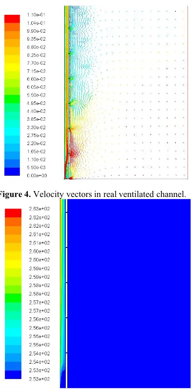
Numerical experiment had also been performed for real constructions with an absence of air access for providing their nonoptimality in hydraulic point of view. The results of an experiment are shown in figures 4-7.
Figure 4. Velocity vectors in real ventilated channel.
Figure 5. The temperature distribution in the ventilated real channel.
Simulation had been performed for evaluation of effect of design features on air flow in the vertical channel. Such constructions have a rustication joints and densely adjoin to pedestal, impeding airing from below to the channel. Therefore, these constructions do not provide optimal conditions for heat-gravitational convection. It means an absence of the optimal heat-to-humidity conditions in the building.
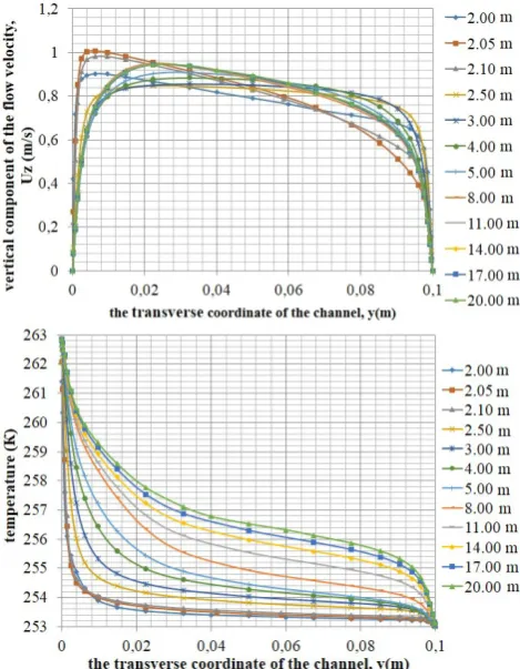
Figure 6. Distribution of the vertical component of the flow velocity in the transverse coordinate of the channel (simulation of real of the channel).
It can be seen that real velocities are far less than in perfect structure and at top point velocity is equal to zero. In perfect structures velocity distribution across the width of an air layer is uniform. In a real structure velocity attain a maximum only in the midpoint of the layer. Boundary layer distribute almost across the width of the layer, heat transfer coefficient is small, moisture removal is ineffective.
Figure 7. Estimated dependence of the temperature on the transverse coordinate of the channel (simulation of real of the channel).
Figure shows that temperature distribution in a real structures is almost linear. This is evidenced by absence of convection.
4 Physical model
Installations of the first group are for verification of convection mathematical model. They represent lengthful vertical and inclined plates, that work in conditions of constant temperature of the surface or in case of constant heat flow on surface of the plate. Boundary layer of ascending force on this surface expanding along the plate with no limits. An absence of cold adiabatic surface distorts the results and restrict their using for real structures.
Isothermal surface and surface in case of constant heat flow are not realized in a real ventilated channels. Usually dissipation from hot surface to flow is known. These installations overlook design features, that are used for hinged ventilated façade: entry and exit conditions of the flow, existence of rustication joints and others.
Installations of the second group are applied for boiler construction, engine technology and others. For these technical fields studying of convection for capillary liquid and molten metal is of current concern Studying of heat-gravitational convection of an air in channels of HVF demands development of a special ohysical model. It should take into account real design features of the ventilated layer. It is necessary to vary with L/h, entry conditions of the flow to channel from free and impactless to its absence, presence of rustication joints, their values and frequency distribution along the hot. There must be heat source, that provides density of heat flow, according to operation of real structures. Cold surface, that imitates façade, should be adiabatic.
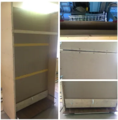
Physical model of the vertical ventilated layer features installation 2050 mm high and 600 mm wide, it has two edges, bounding an air gap and imitating lining layer and wall of the building. One of the edge of the installation is heated and fixed, the second one imitates cladding layer, it is unheated and moveable. It can be created different width h of an air gap in the range of 20-300 mm. Unheated edge consists on sheets of 300 mm, separated by gaps simulating rustication joints by 5 mm. It is possible to control air access from the bottom of the channel in the installation. Regulation of an air access is realized by dint of the seal, capable of restricting of an air access either in part or in whole.
Figure 8. Installation for physical experiment.
Thus, installation allows to carry out experiments by adjusting the conditions of air inlet, geometrical parameters of an air gap and the quantity of heat radiated by the heated edge.
To confirm theoretical calculations, numerical experiment and for studying the effects of rustication joints and air access series of experiments had been performed in the following sizes and configurations of the installation:
1st case: air access to the bottom of the installation is fully open, rustication joints are hermetically sealed (imitation of the perfect channel).
2nd case: air access to the bottom of the installation is fully open, rustication joints are presented (imitation of the channel, closer to real conditions).
3rd case: air access to the bottom of the installation is partially-obscured, rustication joints are presented (imitation of the channel, closer to the real conditions of design changes).
4th case: air access to the bottom of the installation is fully closed, rustication joints are presented (imitation of the real channel).
On each occasion the width of an air gap was variable and changed within the range 20 to 300 mm, the height of the air layer was constant and was equal to 2050 mm. Before starting of series of experiments, the temperature in the laboratory was equal to 293 K. During the experiment, on each occasion an average velocity and temperature of an air flow in the channel at each width of an air gap was measured by dint of hot-wire anemometer.
Air velocity varied between 0 m/s and 0.4 m/s, the temperature varied between 298.6 K and 301.2 C. Data reduction process was performed for each of the four series of experiments. As the variables there were used L/h and v/ gL. The results are shown in figure 11-12. One of experiments is considered as a probe (first case). The purpose of the test experiment - to estimate the value of the coefficient of hydraulic friction. Basic functional connection used in the processing of the experiment is as follows:
(
Th Tc)
ThgL
v/ =
ϕ
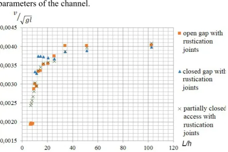
2 − / (11)Figure 9. Dependence of froude number on geometric parameters of the channel.
Figure 10. Dependence of froude number on geometric parameters of the channel.
From all results it follows: in the "perfect channel" (air access to the bottom of the installation is fully open, rustication joints are hermetically sealed) air velocity is maximal. This is evidenced by the results of numerical simulations. Existence of rustication joints even in the open channel reduces the maximum value of Froude number at least twice. Therefore rustication joints are an additional local hydraulic resistance, reducing velocity coefficient ϕ. Closed channel in presence or absence of rustication joints operates at significantly lower values Froude number. Probably, there is no directional heat-gravitational motion, determining lower value of an average velocity for all values of L/h.
5 Conclusions
1. Hydraulic model of heat-gravitational flow in a vertical ventilated layer was developed.
2. Limit values of an average velocity, heat transfer rate, head loss, average temperature of the flow ensuring removal of the dew point in the air gap were evaluated. Basic functional connection was obtained.
3. Numerical simulation of plane flow in conditions of heat-gravitational convection had been performed. 4. Calculation data and experiments showed that the
maximum value of an average velocity attained in the vertical channel with fully open air access in the absence of rustication joints. In a channel with closed air access air infiltration through rustication joints provides reducing of an average velocity at least twice in comparing with an open access channel.
5. Design of the gap is offered - installation of accelerating cascade with blockage degree less than 1/2 of the input section of the channel.
References
1. N. Mingotti, T. Chenvidyakarn, A. Woods, Build. Environ.46, 807-823 (2011)
2. F.M. Silva, G. Gomes, M. Rodrigues, Build. Environ.87, 292-301(2015)
3. C. Popaa, D. Ospir, S. Fohannoa, C. Chereches, Energ. Buildings 50, 229–233 (2012)
4. M. Mourshed, S. Shikder, A. Price, Adv. Eng. Inform.25, 676–687 (2011)
5. R. Fuliotto, F. Cambuli, N. Mandas, N. Bacchin, G. Manara, Q. Chen, Energ. Build. 42, 23–28 (2010)
6. N. Hashemi, R. Fayaz, M. Sarsha, Energ. Buildings 42, 1823–1832 (2010)
7. S. Lee, S. Kim, Y. Na (2015) Energ. Buildings 99, 67–74 (2015)
8. A. Chabauda, J. Eynarda, S. Grieu, Energ. Buildings 99, 9–31 (2015)
9. F. Favoinoa, Q. Jinb, M. Overend, Energ. Proc.
62, 289–298 (2014)
10. W. Tizani, M. Mawdesley, Adv. Eng. Inform.25, 569–572 (2011)
11. J. Ploennigs, A. Ahmed, B. Hensel, P. Stack, K. Menzel, Adv. Eng. Inform.25, 688–698 (2011) 12. L. Gracia, Navarro, A. Castell, L. Cabeza, Appl.
Therm. Eng.61, 372-380 (2013)
13. W. Pasut, M. Carli, Appl. Therm. Eng. 37, 267-274 (2012)
14. C-S. Park, G. Augenbroe, Automat. Constr. 30, 50–56 (2013)
15. A. Hunter, N. Williams, J. Rayner, L. Aye, D. Hes, S. Livesleya, Ecol. Eng.63, 102-113 (2014) 16. A.L.S. Chan, T.T. Chow, Energ. Buildings 69
(2014)
17. N. Mingottia, T. Chenvidyakarn, A.W. Woods, Energ. Buildings 58, 237–249 (2013)
18. H. Radhi, S. Sharples, F. Fikiry, Energ. Buildings
56, 179–188 (2013)
19. W. Loua, M. Huanga, M. Zhang, N. Lin, Energ. Buildings 54, 179–191 (2012)
20. T. Ayinde, S. A. M. Said, M. Habib, Int. J. Heat. Mass Trans. 44, 1207-1216 (2008)
21. T. Yilmaz, . Gilchrist, Int. J. Heat. Mass Trans.
43, 707-719 (2007)
22. D. Vuksanovic, V Murgul, N. Vatin, V. Pukhkal, Appl. Mech. Mater. 725-726 (2014)
23. M. Peni, N. Vatin, V. Murgul, Appl. Mech. Mater. 680, 534-538 (2014)
24. V. Pukhkal, N. Vatin, V. Murgul, Appl. Mech. Mater. 680, 529-533 (2014)
25. A. de Gracia, L. Navarro, A. Castell, L. F. Cabeza, Appl. Therm. Eng. 61, 372-380 (2013)
26. E. Abu-Nada, Int. J. Heat Fluid Fl. 29(1), 242-249 (2008)
27. E. Abu-Nada, Numer. Heat Tr. Part A 58, 660-679 (2010)
28. H. Oztop, E. Abu-Nada, Int. J. Heat Fluid Fl. 29, 1326-1336 (2008)