118 | P a g e
EXOSKELETON ARM USING ARDUINO
Kemala.M
1, Lalitha.B
2, Vinitha.S
3, Megala.D
4AP(ECE)
1,2,3,4
Department of ECE, SEC- Tiruchengode (India)
ABSTRACT
The purpose of this thesis was to find an optimal way to construct and control a product that could help those who suffer from muscle weakness or a muscle sickness. The device was made out of major part (upper arm) which were connected through a motorized joint. The focus was on finding a satisfying construction that could handle the forces and with the help of sensors measure movement of the users arm relative to the construction and then control it using that information. The device needed to be fast and reliable and react to small movements to be as comfortable for the user as possible. The result was a construction controlled by measuring the forces from the user’s movement with the use of force sensors placed at the wrist. The construction managed to follow the users’ arm, fast and in a satisfactory way.
Introduction
A lot of people are suffering from different types of muscle sicknesses and muscle weaknesses. To neither be able to lift everyday things nor move your body as you please is a struggle for many. The most common reason is muscle detritions due to aging, which in some degree affects all of us. Another reason is Fibromyalgia, which is a fairly common type of disease. Most people suffering from fibromyalgia feel exhausted, moving limbs and lifting things can be very painful [1]. Another common reason why a person may suffer from muscle weakness is if the muscle has been crushed, for example, in an accident. Whatever the reason is for suffering from muscle weakness those people would gain a lot from support with lifting objects.
One existing project today with the purpose of assisting lift in one arm and focuses on rehabilitation is the Titan arm [2]. The Titan arm is constructed with cables connected from a motor on the user’s back to a wheel placed on the elbow of the weakened arm. A joystick in the other hand is used to control the movement of the arm. This construction is large and mechanically advanced, while the controlling part is simple and reduces the number of free hands for the user. By using a joystick, you strengthen one of the arms and make the other unable to lift or carry other items. This method is not the best as a solution were the user could control the construction with the same arm as it is mounted on would be preferable. The most optimal solution would be controlling the construction directly from the brain via the nerves, though this technology is not easily available and invasive, therefore it is not an option for this project.
119 | P a g e
activities instead of the nerves, without being invasive. So research is needed to find the best way to construct an exoskeleton arm.
Method
Full size prototypes were constructed in an iterative process to find the optimal structural solution. Low cost materials were used to be able to easily change and enhance the design until a good solution was found. Then the quality of the materials was improved. CAD models were also to be constructed to test performance of materials and different design structures to ensure that the structure could withstand expected loads without having to buy expensive materials or expensive test rigs.
To be able to verify if the construction was responsive to movement it was physically tested with human movement. A servo was also used to simulate human arm movement and then the signals from the sensors and controller were monitored and compared to the signals used to control the servo. If signals from the sensors corresponded with the signals to the servo, independent of the amplitude, the system was constructed in a satisfactory way. Different constructions and controllers could be compared with each other using the simulated arm.
A computer model could have been used to calculate the correct parameters for the controller. The problem would then be to build a correct model, as many parameters were unknown and the construction was modified along the way which meant new models would have been needed. Not using this method from the beginning gave more flexibility and allowed fast changes of the construction. The arm needs to be light enough to not hurt the user more than the lift itself but still be able to withstand the forces and loads that will be applied to it. That can be achieved by using the right material and the right design.
Microcontroller
The project used an Arduino UNO, which is a microcontroller. It was used as the main computer that did all the calculations needed to control the motor from the signals from the sensors and then sent the calculated control signals to the motor controller. It is based on the ATmega328P chip and it has a 16 MHz crystal [8]. In the demonstrator it was powered via USB but it could be powered with a 5 V battery. How it was connected in the system relative to the other parts can be seen in figure 3.3.
Sensor
The force-sensing resistors that were used were the FSR 0.5” (12.7 mm) from Interlink Electronics. They were compact and gave a noise-free signal when force was applied directly to them.
Motor
The magnet field sensors that were used were the KMZ10A from Philips. This sensor was of an analog type so it gave a gradient of values depending on the magnetic fields strength. The sensitivity was rather low though so a range of 14 steps was what was obtained from the sensors.
120 | P a g e Motor driver
The motor driver that was used in the demonstrator was the VNH3SP30 from Pullout. It was capable of controlling a current of up to 9 A and voltage of 16 V [9]. It could handle higher currents without overheating but only during shorter periods. It has a max PWM frequency of 10 kHz. With a control-frequency within the audible spectrum a high frequency noise was heard from the motor when running.
Structural design of the arm
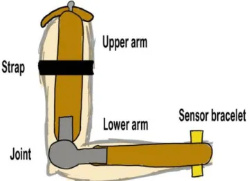
The exoskeleton arm was placed along with the user’s arm. To ensure that the joint of the arm and the user’s arm were in the same axis the upper arm needs to be extendible. To mount the arm on the user the structure was to have some sort of straps but only to the upper arm. The user’s lower arm needs to be able to move freely from the structure so that movement can be monitored. Because of the weight, the arm needed to be fastened with a strap on the upper arm and also be supported by a shoulder part, see figure 2.2.
Figure 2.2 The important parts of the structure seen on a user’s arm
Software
The Arduino were programmed using Arduinos IDE. The flowchart of the project with the software. When the user moved their arm, it affected the sensors. One sensor got an increased signal and one got a decreased signal because force was applied upwards or downwards to move the arm. The signals were then processed to get rid of disturbances and then the difference between the signals was the error. This signal was sent to the controller that calculated in which direction and how much the motor should rotate to compensate for the error. The controller took the error and fed it into the PID-controller.
To make sure that the I-part of the controller did not increase too much anti-windup was implemented. By putting an upper and lower limit on allowed values of the I-part the maximum signal due to constant error was limited.
121 | P a g e Conclusion
The importance of a good sensor arrangement and sensor mounting was found to be greater than expected as it greatly affects the end result. It also proved to be more difficult to fulfill than expected. The bracelet construction proved successful and gave good results independent of the amplitude of the movement.
Future work
The sensing technology in the system is applicable on other joints, such as the knee, shoulder or wrist. Modification on the driving mechanism would be needed in case of the shoulder and wrist as they have more degrees of freedom. Including the hand and wrist in the structure would be a great improvement as this would allow the user to use their own hands to grab objects and thereby be able to get support when lifting a greater range of objects.
Research into construction of light and effective power source, like battery packs would be a good idea as the construction now is bounded by wires. A battery pack would make the construction wireless and allow the user a greater range of movement when wearing the structure.
122 | P a g e
REFERENCES
[1] Fibromyalgi förbundet, http://www.fibromyalgi.se/1.0.1.0/571/1/ searched 2016-03-02 [2] Titan arm, http://titanarm.com/about searched 2016-03-07
[3] Isacsson, M. Muscle to motor communication (Bachelor’s thesis, KTH), 2015 [4] Ultrasonic blind spot,
http://www.ab.com/en/epub/catalogs/12772/6543185/12041221/12041229/print.h tml, searched 2016-03-10
[5] Magnetic field sensor,
http://www51.honeywell.com/aero/common/documents/myaerospacecatalog- documents/Defense_Brochures-documents/Magnetic__Literature_Technical_Article-documents/A_New_Perspective_on_Magnetic_Field_Sensing.pdf searched 2016-03-10
[6] Force sensitive resistors. http://www.interlinkelectronics.com/datasheets/Datasheet_FSR.pdf searched 2016-03-10
[7] Glad T. and Ljung L., ”Reglerteknik”, Edition 4:12, 2006, pp 20-21.