Abstract— Transforms are widely used for image and video compression. It is used to convert spatial domain values of the frames to frequency domain values. In this paper a new Multistandard Transform core (MST) is designed to support MPEG-1/2/4 (8x8), H.264 (8x8, 4x4), VC-1(8x8, 4x4, 8x4, 4x8) compression standards. Common Sharing Distributed Arithmetic method (CSDA) is used to share the hardware resources in this transform core design. The buffer registers are used as pipeline registers instead of using D flip-flops for reducing area and power consumption. The language which is used to build this architecture is Verilog HDL
Index Terms— Common Sharing Distributed Arithmetic, Discrete Cosine Transform, Integer Transform, Hadamard Transform,
1. INTRODUCTION
1.1 VIDEO CODECA video CODEC encodes a source image or video sequence into a compressed form and decodes this to produce a copy or approximation of the source sequence. If the decoded video sequence is identical to the original, then the coding process is lossless. If the decoded sequence differs from the original, the process is lossy.
A video encoder consists of three main functional units: prediction, transform, entropy encoding. The prediction block which is used to predict the frames from video source which include intra frame prediction, inter frame prediction and motion compensation. The predicted frames are sending to transform which is used to convert spatial domain to frequency domain. The frequency domain values are subjected to quantization which is used to remove high frequency values. After quantization, most of the high frequency coefficients are zero.
To exploit the number of zeros, a zigzag scan of the matrix is used. Zigzag scan allows all the DC coefficients and lower frequency AC coefficients to be scanned first, DC coefficients are encoded using differential encoding and AC coefficients are encoded using run-length encoding. Huffman
coding is used to encode the coefficient after both the coding. The video decoder reconstructs a video frame from the compressed bit stream. The coefficients and motion vectors are decoded by an entropy decoder after which the spatial model is decoded to reconstruct a version of the residual frame. The decoder uses the motion vector parameters, together with one or more previously decoded frames, to create a prediction of the current frame and the frame itself is reconstructed by adding the residual frame to this prediction.
1.2 TRANSFORM DESIGNS
In this project we have concentrate on transform part, which is the conversion of spatial domain to frequency domain. Transform design is different for each compression standard. In existing design Factor sharing, Matrix decomposition method, New Distributed Arithmetic (NEDA), Adder sharing methods are designed to reduce the hardware cost. Hwangbo and Kyung [10] introduced a fully supported transform core for the H.264 standard, including 8x8 and 4x4 transforms. C.P.Fan and G.A.Su [7] introduced a transform core design for VC-1 standard. K.H.Chen, J.I.Guo, J.S.Wang, C.W.Yeh and T.F.Chen [16] introduced DCT/IDCT targeting at MPEG4 shape-adaptive transforms. Some of the existing transform design consumes more gate counts and high power consumption. Some of the transform design supports only one compression standard.
This paper introduces Mutistandard Transform core design that supports MPEG1/2/4 (8x8), VC-1 (8x8, 4x4), H.264 (8x8, 4x4, 8x4, 4x8) standards. The Discrete Cosine Transform is used for MPEG (8x8) compression standard. The Integer transform and Hadamard transform are used for H.264 (8x8, 4x4) compression standard. The Integer transform is used for VC-1 (8x8, 4x4, 8x4, 4x8) standard. Common Sharing Distributed Arithmetic (CSDA) method is the combination of Factor Sharing (FS) and Distributed Arithmetic (DA), which is used to reduce the hardware resources. This method aims to reduce the non-zero elements and also reduce the usage of adders. The chosen Canonic Signed Digital Coefficients are used to achieve excellent sharing capability. The rest of this paper is organized as
Area and Power efficient MST core supported
video codec using CSDA
B.Sutha Sivakumari*, B.Mohan**
*M.E. VLSI Design Email: [email protected] ** Assistant Professor of ECE Department
Email: [email protected]
follows. The section 2 discussed the Mathematical Derivation of proposed 2-D CSDA MST core design. The section 3 discussed about proposed 2-D CSDA MST core and the modules which are used to build this architecture is discussed in the section 4. Example for CSDA algorithm applying to 8-point Integer transform and 4-point Hadamard transform supporting H.264 standard is described in section 5.Example for CSDA algorithm applying to 8-point and 4-point transform supporting VC-1 standard is described in section 6. The comparison table for the 2-D CSDA MST core using buffer registers with 2-D CSDA MST core using D flip-flops and the conclusion which are given in the section 7 and 8.
2.
MATHEMATICAL
DERIVATION
OF
PROPOSED 2-D CSDA-MST CORE DESIGN
2.1 MATHEMATICAL DERIVATION OF
EIGHT-POINT AND FOUR-POINT TRANSFORMS This section explains the proposed 2-D CSDA-MST core implementation. Neglecting the scaling factor, the one dimensional (1-D) eight-point transform can be defined as follows: 0 0 1 1 2 2 3 3 4 4 5 5 6 6 7 7 Z x Z x Z x Z x C Z x Z x Z x Z x (1) Where x0-x7 are the input of the spatial domain values of the
frame, C is the coefficients matrix. By multiplying the input values with coefficient matrix convert the spatial domain values are converted into frequency domain values.
4 4 4 4 4 4 4 4 1 3 5 7 7 5 3 1 2 6 6 2 2 6 6 2 3 7 1 5 5 1 7 3 4 4 4 4 4 4 4 4 5 1 7 3 3 7 1 5 6 2 2 6 6 2 2 6 7 5 3 1 1 3 5 7 c c c c c c c c c c c c c c c c c c c c c c c c c c c c c c c c C c c c c c c c c c c c c c c c c c c c c c c c c c c c c c c c c (2)
Because the eight-point coefficient structures in MPEG-1/2/4, H.264 and VC-1 standards are the same, the eight-point transform for these standards can use the same mathematic derivation. According to the symmetry property, the 1-D eight-point transform in (2) can be divided into even and odd two four point transforms. Ze and Zo, as listed in (3) and (4) respectively. The coefficient values in the C matrix are different for each standard.
0 4 4 4 4 0 2 2 6 6 2 1 4 4 4 4 4 2 6 6 2 2 6 3 Z c c c c a Z c c c c a Ze Z c c c c a Z c c c c a (3) = Ce.a 1 1 3 5 7 0 3 3 7 1 5 1 5 5 1 7 3 2 7 7 5 3 1 3 Z c c c c b Z c c c c b Zo Z c c c c b Z c c c c b (4) = Co.b Where 0 7 1 6 2 5 3 4 x x x x a x x x x , 0 7 1 6 2 5 3 4 x x x x b x x x x (5)
where a0=x0+x7, a1=x0+x6, a2=x2+x5, a3=x3+x4 and b0=x0-x7, b1=x1-x6, b2=x2-x5, b3=x3-x4. The values of a and b are computed in selected butterfly (SBF) module by choosing the selection signal of mux. For 4-point transform the values of x0-x7 is directly passes through the even part and odd part CSDA without the computation of SBF module.
The even part and odd part of the operation in (3) and (4) are the same as that of the four-point H.264 and VC-1 transformations. Moreover, the even part Ze can be further decomposed into even and odd parts: Zee and Zeo.
0 4 4 0 4 4 4 1 Z c c A Zee Z c c A (6) = Cee.A 2 2 6 0 0 6 6 2 1 Z c c B Ze Z c c B (7) = Ceo.B Where A= 0 3 1 2 a a a a , B= 0 3 1 2 a a a a (8)
Where A0=a0+a3, A1=a1+a2, B0 = a0-a3, B1= a1-a3. The values A and B are computed in the first stage of selected butterfly in the even part CSDA circuit.
2.1.1 DCT coefficient matrix:
The formula which is used to find the DCT (N=8) eight point coefficient structure (MPEG 1/2/4) is,
Ci,j = 1 / N,where i=0, 0≤ j≤ N-1 2 / NCOS 2
2
ij i N
, where 1≤ i ≤ N-1 ,0≤ j≤N-1 (9)
The solved above equation is used in the matrix format of equation (2).
2.1.2 Hadamard coefficient matrix:
The hadamard coefficient matrix for H.264 (4x4) is given by,
1 1 1 1 1 1 1 1 1 1 1 1 1 1 1 1 H (10)
For the representation of 3-bit Canonic Signed Digit, H matrix will be divided by 4 and the values are used in the equation (3).
2.1.3 Integer coefficient matrix:
From [5] the integer coefficient matrix for H.264 (8x8) is given by, 8 8 8 8 8 8 8 8 12 10 6 3 3 6 10 12 8 4 4 8 8 4 4 8 10 3 12 6 6 12 3 10 1 8 8 8 8 8 8 8 8 6 12 3 10 10 3 12 6 4 8 8 4 4 8 8 4 3 6 10 12 12 10 6 3 I (11)
For the representation of 5-bit Canonic Signed Digit, I1 matrix will be divided by 16 and the values are used in the equation (2).
From [5] the integer coefficient matrix for H.264 (4x4) is
1 1 1 1 2 1 1 2 2 1 1 1 1 1 2 2 1 I (12)
For the representation of 3-bit Canonic Signed Digit, I2 matrix will be divided by 4 and the values are used in the equation (3).
From [14] the integer coefficient matrix for VC-1 (8x8) is,
12 12 12 12 12 12 12 12 16 15 9 4 4 9 15 16 16 6 6 16 16 6 6 16 15 4 16 9 9 16 4 15 3 12 12 12 12 12 12 12 12 9 16 4 15 15 4 16 9 6 16 16 6 6 16 16 6 4 9 15 16 16 15 9 4 I (13)
For the representation of 6-bit Canonic Signed Digit, I3 matrix will be divided by 32 and the values are used in the equation (2).
From [14] the integer coefficient matrix for VC-1 (4x4) is
17 17 17 17 22 10 10 22 4 17 17 17 17 10 22 22 10 I (14)
For the representation of 6-bit CSD, I4 matrix will be divided by 32 and the values are used in the equation (3).
2.2
COMMON
SHARING
DISTRIBUTED
ARITHMETIC (CSDA) COEFFICIENTS OF THE
PROPOSED MULTISTANDARD TRANSFORM
This section provides the list of the coefficients of the Canonic Signed Digit (CSD) expression, where indicates -1. These values are obtained by solving the corresponding transform equations.
The chosen coefficients of CSD expression listed in table I and II can achieve high sharing capability for arithmetic resources by using proposed CSDA algorithm. Canonic Signed Digit Expressions for the Proposed CSDA-MST Coefficients for 8-point transform is given in the Table I. Canonic Signed Digit Expressions for the Proposed CSDA-MST Coefficients for 4-point transform is given in the Table II.
Table I
Canonic Signed Digit Expressions for the Proposed CSDA-MST Coefficients for 8-point transform
Dimension Eight-point
Standards MPEG 1/2/4 H.264
Integer Transform
VC-1 Integer Transform
Coefficients value 12-bit
CSD value 5-bit CSD Value
6 bit CSD c1 0.4904 001111101100 0.75 01100 0.5 010000 c2 0.4619 001110110010 0.5 01000 0.5 010000 c3 0.4157 001101010011 0.625 0.46875 c4 0.3536 001011010100 0.5 01000 0.375 001100 c5 0.2778 0.375 00110 0.28125 001001 c6 0.1913 000110001000 0.25 00100 0.1875 000110 c7 0.0975 000011001000 0.1875 00011 0.125 000100
Example:
The value c1for MPEG1/2/4 will be expressed as c1=
2
2+2
3+2
4+2
5+2
6+2
8+2
9~=0.4904
The value c1 for H.264 will be expressed as c1=
2
1+2
2=0.75
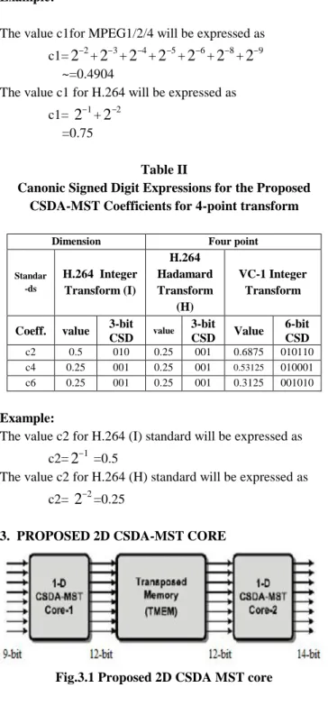
Table II
Canonic Signed Digit Expressions for the Proposed CSDA-MST Coefficients for 4-point transform
Dimension Four point
Standar -ds H.264 Integer Transform (I) H.264 Hadamard Transform (H) VC-1 Integer Transform
Coeff. value 3-bit CSD value 3-bit CSD Value 6-bit CSD c2 0.5 010 0.25 001 0.6875 010110 c4 0.25 001 0.25 001 0.53125 010001 c6 0.25 001 0.25 001 0.3125 001010 Example:
The value c2 for H.264 (I) standard will be expressed as c2=
2
1 =0.5The value c2 for H.264 (H) standard will be expressed as c2=
2
2=0.253. PROPOSED 2D CSDA-MST CORE
Fig.3.1 Proposed 2D CSDA MST core
The proposed 2-D CSDA-MST core (Core-1 and Core-2) with a transposed memory (TMEM). The output data from Core-1 can be transposed and fed into Core-2. Each core has four pipeline stages: two in the even and odd part CSDA circuit, and two in Error Compensated Adder Trees. This architecture uses pipeline registers with buffer registers rather than D-flip flops for even part and odd part to store the results of previous stage. Both flip-flops and buffers are used for the same purpose i.e. for holding the circuit data for the specific clock period. But in the case of area reduction these buffers can be used in the place of flip-flops because of the minimum number of gate counts The buffer register takes only two nand gates to store the data, where the register with D-flip-flops takes six nand gates. The advantages of proposed system are low power consumption and less area. It supports
MPEG-1/2/4,H.264,VC-1 transforms with a reduced hardware cost
4. MODULES
The modules which are used to build 2-D CSDA MST core are explained below.
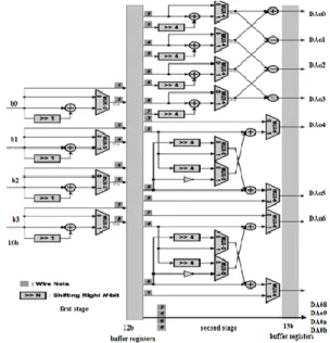
4.1 1-D Common Sharing Distributed arithmetic-MST The architecture of the 1-D CSDA MST core is shown in Fig 4.1, which consists of a Selected Butterfly (SBF) module, an Even part CSDA (CSDA_E), an Odd part CSDA (CSDA_O), Eight Error Compensated Trees (ECATs) and a permutation module. Based on the proposed CSDA algorithm, the coefficients for MPEG-1/2/4, H.264, and VC-1 transforms are chosen to achieve high sharing capability for arithmetic resources. For MPEG-1/2/4 standard, the multiplexer selection signals are chosen to perform Discrete Cosine Transform (8-point) with 12-bit Canonic Signed Digit (CSD) values.
Fig. 4.1 Architecture of the proposed 1-D CSDA-MST The Integer transform with 5-bit CSD values (8-point) is used for H.264 standard. The Integer transform with 3-bit CSD values (4-point) /Hadamard transform with 3-bit CSD values are used for H.264 standard. The Integer transform with 6-bit CSD values (8-point/4-point) is used for VC-1 standard. The SBF module executes for the eight-point transform and by passes the input data for two four-point transforms. After the SBF module, the CSDA_E and CSDA_O execute by feeding input data a and b, respectively. 4.2 Even part Common Sharing Distributed Arithmetic Circuit
The CSDA_E calculates the even part of the eight-point transform, similar to the four-point transform for H.264 and VC-1 standards. Within the architecture of CSDA_E, two pipeline stages exist (12-bit and 13-bit). The first stage executes as a four-input butterfly matrix circuit, and the second stage of CSDA_E then executes by using the proposed CSDA algorithm to share hardware resources in variable
standards.
Fig. 4.2 Architecture of even part CSDA
4.3 Odd part Common Sharing Distributed Arithmetic circuit
Similar to the CSDA_E, the CSDA_O also has two pipeline stages. Based on the proposed CSDA algorithm, then CSDA_O efficiently shares the hardware resources among the odd part of the eight-point transform and four-point transform for variable standards. It contains selection signals of Multiplexers (MUXs) for different standards. Eight adder trees with error compensation are followed by the CSDA_E and CSDA_O, which add the nonzero CSDA coefficients with corresponding weight as the tree-like architectures. The Error Compensated Adder Tree (ECATs) circuits can alleviate truncation error efficiently in small area design when summing the nonzero data all together.
Fig. 4.3 Architecture of odd part CSDA
This 1-D Common Sharing Distributed Arithmetic (CSDA) MST Core is designed with seven multiplexers in order to choose the appropriate standard transforms. The selection signals of multiplexers for appropriate standards are shown in the table III, where M represents MUX.
Table III
Selection Signals of Multiplexers for the CSDA-MST standards point M M-1 M-2 M-3 M-4 M-5 M-6 MPEG 8 1 1 1 1 1 0 1 H.264 8 1 0 0 1 0 0 0 4(H) 0 0 0 0 0 1 1 4(I) 0 0 0 0 0 1 1 VC-1 8 1 0 1 0 0 1 1 4 0 0 1 0 1 1 1
4.4 Error Compensation Adder Trees (ECAT)
Eight adder trees with error compensation (ECATs) are followed by the CSDA_E and CSDA_O, which add the nonzero CSDA coefficients with corresponding weight as the tree-like architectures. The ECATs circuits can alleviate truncation error efficiently in small area design when summing the nonzero data all together. The eight output from ECAT directly given to permutation.
Permutation relates to the act of rearranging, or permuting, all the members of a set into some sequence. It is used for encode output matrix. The Error-Compensated Circuit diminishes the truncation error for high accuracy design. Therefore, the hardware size and cost is reduced, and the speed is improved by using the ECAT architecture. 4.5 Transpose Memory (TMEM) Architecture
The 2-D CSDA MST requires the first stage computed transform values to be transposed before second transform is applied. The role of transpose memory for the 2-D CSDA MST core is important.
Fig. 4.4 Folded transpose memory
Each cell consists of a 12 bit register, 12 bit 2:1 multiplexer at the input and a 12 bit 2:1 de-multiplexer at the output. The multiplexer and demultiplexer allow the register file to accept data from either direction as well as to transmit data in either horizontal or vertical direction. All the switching circuits i.e. at the input as well as at the output are controlled through a common control signal. The signal generated by the control unit switches the select lines of the multiplexer and de-multiplexer to switch the direction of data flow after every eight cycles. This implies that the array can now accept an 8x8 data block in the horizontal direction, and start transmitting the transpose through the vertical direction. It should be noted that at the same time as the memory outputs
the transpose in the vertical direction, it can continue accepting new data through the vertical input. This new arrangement described here saves 8 clock cycles per transform block to be processed. This architecture is much better in processing speed than previous architectures.
5. Example for CSDA algorithm applying to 8 point transform and 4 point transform supporting H.264 standard
The term H values are referred as factor shared values and DA is referred as Distributed Arithmetic value. The equations which are performed in each module according to selection of multiplexers for different standard are discussed below. The values a and b are computed in selected butterfly. The values A and B are computed in even part CSDA. The Distributed Arithmetic values (DAe and Dao) are computed in even part and odd part CSDA. For the multiplication of Factor Shared values with a and b, only the shifting operations are used in order to reduce the hardware resources.
The Error Compensated Adder Tree (ECAT) module is used to add the DA values with appropriate weights to compute frequency domain values. The permutation module is used to arrange the computed values from Z to T.
5.1 8-Point Integer Transform
i) Selection Signals Of Multiplexers for H.264 standard
Stand. Point Mux Mux -1 Mux -2 Mux -3 Mux -4 Mux -5 Mux -6 H.264 8 1 0 0 1 0 0 0
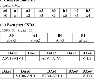
(ii) Selected Butterfly Inputs: x0-x7 a0 a1 a2 a3 b0 b1 b2 b3 x0+ x7 x1+ x6 x2+x5 x3+x4 x0-x7 x1-x6 x2-x5 x3-x4
(iii) Even part CSDA Inputs: a0, a1, a2, a3
A0 A1 B0 B1
a0+a3 a1+a2 a0-a3 a1-a2
DAe0 DAe1 DAe2 DAe3 DAe4
A0H1+A1H1 A0H1-A1H1 H1B1
DAe5 DAe6 DAe7 DAe8 DAe9
H1B0 FS SHARED: H1= [1] =1
Where denotes the un-used DA coefficient in the standard
(iv) Odd part CSDA Inputs: b0, b1, b2, b3
DAo0 DAo1 DAo2 Dao3
H2b0+H2b1 H2b0-H2b2 H2b3-H2b1 H2b2-b3H2
DAo4 DAo5 DAo6 DAo7
H3b1 H3b2 H3b3 H3b0
DAo8 DAo9 DAoa DAob
H2b0 H2b1 H2b2 H2b3
FS SHARED: H2= [11] =1.5, H3= [1] =1
Where denotes the un-used DA coefficient in the standard
(v) Error Compensated Adder Trees Z0=DAe0
2
1Z4= DAe2
2
1Z2=DAe9
2
1+ DAe42
2Z6=-DAe9
2
2 - DAe42
1Z1=DAo0
2
1 + DAo82
2 + DAob2
3 - DAo42
3Z3= DAo1
2
1 - DAob – DAo92
3 - DAo72
3 Z5= DAo22
1 +DAo82
2 +DAo82
3 - DAo62
3 Z7= DAo32
1 –DAo92
2 +DAo82
3 + DAo52
3 (vi) Permutation Module[T0 T1………T7] = [Z0 Z1………..Z7]
5.2 4-Point Hadamard Transform
i) Selection Signals Of Multiplexers for H.264 standard
Stan-dard point Mux Mux -1 Mux -2 Mux -3 Mux -4 Mux -5 Mux -6 H.264 4(H) 0 0 0 0 0 1 1
(ii) Selected Butterfly Inputs: x0-x7
a0 a1 a2 a3 b0 b1 b2 b3
x0 x1 x2 x3 x7 x6 x5 x4
(iii) Even part CSDA Inputs: a0, a1, a2, a3
A0 A1 B0 B1
a0+a3 a1+a2 a0-a3 a1-a2
DAe0 DAe1 DAe2 DAe3 DAe4
A0H1+A1H1 A0H1-A1H1
DAe5 DAe6 DAe7 DAe8 DAe9
FS SHARED: H1= [1] =1
Where denotes the un-used DA coefficient in the standard
(iv) Odd part CSDA Inputs: b0, b1, b2, b3
DAo0 DAo1 DAo2 Dao3
H2b0+H2b1 H2b0-H2b2 H2b3-H2b1 H2b2-b3H2
DAo4 DAo5 DAo6 DAo7
b0H2-H2b3 H2b1-H2b2
DAo8 DAo9 DAoa DAob
FS SHARED: H2= [1] =1.
Where denotes the un-used DA coefficient in the standard
(v) Error Compensated Adder Trees Z0=DAe0
2
2 Z4= DAe22
2 Z2=DAe72
2 Z6=-DAe62
2 Z1=DAo02
2 + Dao32
2 Z3= Dao42
2 + Dao62
2 Z5= DAo22
2 + Dao12
2 Z7= Dao42
2– Dao6 22
(vi) Permutation Module
[T0 T1 T2 T3] = [Z0 Z2 Z4 Z6] [T4 T5 T6 T7] = [Z1 Z3 Z5 Z7]
6. Example for CSDA algorithm applying to 8 point transform and 4 point transform supporting VC-1 standard
The term V is referred as factor shared value and DA is referred as Distributed Arithmetic value.
6.1 8 Point Integer Transform
i) Selection Signals Of Multiplexers for VC-1 standard
Stand -ards Poi -nt mux Mux -1 Mux -2 Mux -3 Mux -4 Mux -5 Mux -6 VC-1 8 1 0 1 0 0 1 1
(ii) Selected Butterfly Inputs: x0-x7 a0 a1 a2 a3 b0 b1 b2 b3 x0+ x7 x1+ x6 x2+x5 x3+x4 x0-x7 x1-x6 x2-x5 x3-x4
(iii) Even part CSDA Inputs: a0, a1, a2, a3
A0 A1 B0 B1
a0+a3 a1+a2 a0-a3 a1-a2
DAe0 DAe1 DAe2 DAe3 DAe4
A0V2+A1V2 A0V2-A1V2 V1B1
DAe5 DAe6 DAe7 DAe8 DAe9
B1V2 V2B0 V1B0
FS SHARED: V1= [1] =1, V2=[11]=1.5,
Where denotes the un-used DA coefficient in the standard
(iv) Odd part CSDA Inputs: b0, b1, b2, b3
DAo0 DAo1 DAo2 Dao3
V3b0+V3b1 V3b0-V3b2 V3b1-V3b3 V2b3-b3V3
DAo4 DAo5 DAo6 DAo7
b0V3-V3b3 V3b0+V3b3 V3b1-V3b2 V3b1+ V3b2
DAo8 DAo9 DAoa DAob
V3b0 V3b1 V3b3
FS SHARED: V3= [1] =1,
Where denotes the un-used DA coefficient in the standard
(v) Error Compensated Adder Trees Z0=DAe0
2
2Z4= DAe3
2
2Z2=DAe9
2
1+ DAe52
3Z6=-DAe8
2
2- DAe42
1Z1=DAo0
2
2 + DAoa2
2+DAob2
3-DAo12
5Z3= DAo2
2
1 + DAo32
2+DAo82
3-DAo42
5Z5= DAo1
2
1 - DAob2
2-DAo92
3-DAob2
5Z7= Dao3
2
1 - DAo92
2-DAo82
3-DAo72
5(vi) Permutation Module
[T0 T1………T7] = [Z0 Z1………..Z7] 6.2 4 Point Integer Transform
i) Selection Signals Of Multiplexers for VC-1 standard
Stand -ards Poi -nt mux Mux -1 Mux -2 Mux -3 Mux -4 Mux -5 Mux -6 VC-1 4 0 0 1 0 1 1 1
(ii) Selected Butterfly Inputs: x0-x7
a0 a1 a2 a3 b0 b1 b2 b3
x0 x1 x2 x3 x7 x6 x5 x4
(iii) Even part CSDA Inputs: a0, a1, a2, a3
A0 A1 B0 B1
a0+a3 a1+a2 a0-a3 a1-a2
DAe0 DAe1 DAe2 DAe3 DAe4
A0V1+A1V1 A0V1-A1V1 V1B1
DAe5 DAe6 DAe7 DAe8 DAe9
V1B0-V2B1 V2B0+V2B1 V1B0
FS SHARED: V1= [1] =1, V2= [11] =1.5,
Where denotes the un-used DA coefficient in the standard
(iv) Odd part CSDA Inputs: b0, b1, b2, b3
DAo0 DAo1 DAo2 Dao3
V3b0+V3b1 V3b0-V3b2 V3b3-V3b1 V3b2+b3V3
DAo4 DAo5 DAo6 DAo7
b0V4-V4b3 V4b1-V4b2
DAo8 DAo9 DAoa DAob
V4b0 V4b3
FS SHARED: V3= [10001] =1.0625, V4= [1]=1, Where denotes the un-used DA coefficient in the standard
(v) Error Compensated Adder Trees
Z0=DAe0
2
1+DAe02
5Z4= DAe2
2
1 + DAe22
5Z2=DAe9
2
1 +DAe72
3+DAe42
3Z6=-DAe4
2
1-DAe62
3+DAe92
3Z1=DAo0
2
1 + Dao32
1Z3= DAo8
2
2 + DAo62
2+ DAo42
3 + DAo62
4-DAob2
1Z5= DAo2
2
1 + DAo12
1Z7= DAo
2
4– DAo6 12
-DAo62
3-DAo62
4+ DAo42
4(vi) Permutation Module
[T0 T1 T2 T3] = [Z0 Z2 Z4 Z6] [T4 T5 T6 T7] = [Z1 Z3 Z5 Z7]
7. COMPARISION TABLE
Verilog HDL is used to build this MST core design. This 2-D MST core design is synthesized by using Xilinx software and the comparison results are shown in the Table IV.
Table IV
Comparison table between 2-D CSDA MST architecture using D flip-flops and buffer registers
2-D Common sharing Distributed Arithmetic Multistandard transform architecture
Registers D Flip-flops Buffers
Supporting standards MPEG 1/2/4 H.264 VC-1 MPEG 1/2/4 H.264 VC-1 Gate counts 28.6 k. 23.7 k. Power consumption 0.362W 0.254W
The comparison results shows that 2-D CSDA MST architecture using buffer registers supports three standards as well as the power consumption and gate counts are considerably reduced.
8. CONCLUSION
The 2-D CSDA MST core can achieve high performance, with low - cost VLSI design supporting MPEG-1/2/4, H.264, and VC-1 standards. This MST core can support MPEG-1/2/4, H.264 and VC-1 standards by using the selection signals of multiplexers. By using the proposed CSDA method with buffer registers instead of D flip-flops, the gate counts and power consumption can be reduced efficiently.
REFERENCES
[1] Chen Y.H., Chen J.N., Chang T.Y., Lu C.W., (2014) ‘High throughput Multistandard transform core supported mpeg 1/2/4, H.264, VC-1 using Common Sharing Distributed Arithmetic’, Very Large Scale
Integration (VLSI) Systems, IEEE Transactions on (Volume:22
, Issue: 3 )
[2] August N.J., and Ha D.S.,(2004) ‘Low power design of DCT and IDCT for low bit rate video codecs’, IEEE Trans. Multimedia, vol. 6, no. 3, pp. 414–422.
[3] Butts M., (2007) ‘Synchronization through communication in a massively parallel processor array’, IEEE Micro, vol. 27, no. 5, pp. 32–41.
[4] Chen J.W., Chen K.H., Wang J.S., and Guo J.I.,(2006) ‘A performance aware IP core design for multi-mode transform coding using scalable-DA algorithm’ in Proc. IEEE Int. Symp. Circuits Syst.,pp. 1904–1907.
[5] Chen K.H., Guo J.I, and Wang J.S.,(2006) ‘A high-performance direct 2D transform coding IP design for MPEG-4AVC/H.264’, IEEE
Trans.Circuits Syst. Video Technol., vol. 16, no. 4, pp. 472–483.
[6] Chen W., Smith C., and Pralick S.,(1977), ‘A fast computational algorithm for the discrete cosine transform’ , IEEE Trans. Commun., vol. 25, no. 9,pp. 1004–1009.
[7] Chen Y.H., Chang T.Y. and Li C.Y.,(2011) ‘High throughput DA-based DCT with high accuracy error-compensated adder tree’,
IEEE Trans. Very Large Scale Integr. (VLSI) Syst., vol. 19, no. 4, pp.
709–714.
[8] Fan C.P. and Su G.A.,(2009) ‘Efficient fast 1-D 8×8 inverse integer transform for VC-1 application’, IEEE Trans. Circuits Syst. Video
Technol.,vol. 19, no. 4, pp. 584–590.
[9] Fan C.P. and Su G.A.,(2009) ‘Fast algorithm and low-cost hardware- sharing design of multiple integer transforms for VC-1’, IEEE Trans.
Circuits Syst., vol. 56, no. 10, pp. 788–792.
[10] Huang C.Y., L. F. Chen L.F., and Y. K. Lai Y.K., (2008) ‘A high-speed 2D transform architecture with unique kernel for multi-standard video applications’, in Proc. IEEE Int. Symp. Circuits Syst., pp. 21–24. [11] Hwangbo W. and Kyung C.M., (2010) ‘A multitransform architecture
for H.264/AVC high-profile coders’, IEEE Trans. Multimedia, vol. 12, no.3,pp. 157–167.
[12] Li.W.,(2001),‘Overview of fine granularity scalability in MPEG-4 video Standard’, IEEE Trans. Circuits Syst. Video Technol., vol. 11, no. 3,pp. 301–317.
[13] Schwarz H., Marpe D., and Wiegand T.,(2007) ‘Overview of the scalable video coding extension of the H.264/AVC standard’, IEEE
Trans. Circuits Syst.Video Technol., vol. 17, no. 9, pp. 1103–1120.
[14] Shams A.M., Chidanandan A., Pan W. and M. A. Bayoumi M.A., (2006) ‘NEDA: A low-power high-performance DCT architecture’,
IEEE Trans. Signal Process., vol. 54, no. 3, pp. 955–964.
[15] Srinivasan.S et al., (2004) ‘Windows media video 9: Overview and applications’, Signal Processing: Image Communication, vol. 19, no. 9, pp. 851–875.
[16] Yu S. and Swartzlander E.E., (2001) ‘DCT implementation with distributed Arithmetic’, IEEE Trans. Comput., vol. 50, no. 9, pp. 985–991.