Design and Implementation of 11:2 Compressors
for Fast Addition
T.Rajyalakshmi
Dept. of E. C.E (VLSI System Design). Sreenivasa Institute of Technology and Management
Studies Chittoor, A.P, India.
Y.Ravikiran Varma,(Assistant proffessor) Dept. of E.C.E (VLSI System Design). Sreenivasa Institute of Technology and Management
Studies,chittoor,A.P,India
Abstract— In this paper Although redundant addition is widely used to design parallel multi operand adders for ASIC implementations, the use of redundant adders on Field Programmable Gate Arrays (FPGAs) has generally been avoided. The main reasons are the efficient implementation of carry propagate adders (CPAs) on these devices (due to their specialized carry-chain resources) as well as the area overhead of the redundant adders when they are implemented on FPGAs.
This paper presents different approaches to the efficient implementation of generic carry-save compressor trees on FPGAs. we present a fast critical path, independent of bit width, with practically no area overhead compared to CPA trees. Along with the classic carry-save compressor tree, we present a novel linear array structure, which efficiently uses the fast carry-chain resources. This approach is defined in a parameterizable HDL code based on CPAs, which makes it compatible with any FPGA family or vendor. A detailed study is provided for a wide range of bit widths and large number of operands. Compared to binary and ternary CPA trees, speedups of up to 2.29 and 2.14 are achieved for 16-bit width and up to 3.81 and 3.11 for 64-bit width.
Keywords— Computer arithmetic, reconfigurable hardware, multioperand addition, redundant representation, carry-save adders and Verilog.
I. INTRODUCTION
The use of Field Programmable Gate Arrays (FPGAs) to implement digital circuits has been growing in recent years. In addition to their reconfiguration capabilities, modern FPGAs allow high parallel computing. FPGAs achieve speedups of two orders of magnitude over a general-purpose processor for arithmetic intensive algorithms. Thus, these kinds of devices are increasingly selected as the target technology for many applications, especially in digital signal processing, hardware accelerators cryptography and much more. Therefore, the efficient implementation of generalized operators on FPGAs is of great relevance.
The typical structure of an FPGA device is a matrix of configurable logic elements (LEs), each one surrounded by interconnection resources. In general, each configurable element is basically composed of one or several n-input lookup tables (N- LUT) and flip-flops. However, in modern FPGA architectures, the array of LEs has been augmented by including specialized circuitry, such as dedicated multipliers, block RAM, and so on. In the authors demonstrate that the
intensive use of these new elements reduces the performance GAP between FPGA and ASIC implementations.
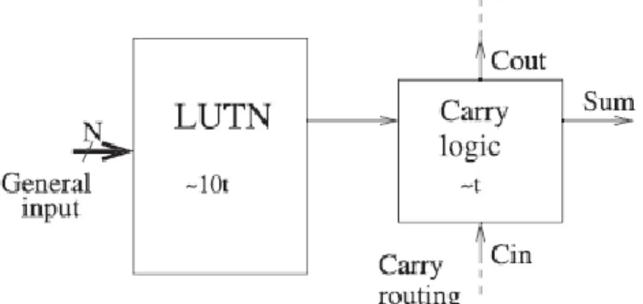
One of these resources is the carry-chain system, which is used to improve the implementation of carry propagate adders (CPAs). It mainly consists of additional specialized logic to deal with the carry signals, and specific fast routing lines between consecutive LEs, as shown in Fig. 1. This resource is presented in most current FPGA devices from low-cost ones to high-end families, and it accelerates the carry propagation by more than one order of magnitude compared to its implementation using general resources. Apart from the CPA implementation, many studies have demonstrated the importance of using this resource to achieve designs with better performance and/or less area requirements, and even for implementing non arithmetic circuits. Multi operand addition appears in many algorithms, such as multiplication, filters ,SAD and others. To achieve efficient implementations of this operation, redundant adders are extensively used. Redundant representation reduces the addition time by limiting the length of the carry-propagation chains.
The most usual representations are carry-save (CS) and signed-digit (SD). A CS adder (CSA) adds three numbers using an array of Full-Adders (FAs), but without propagating the carries. In this case, the FA is usually known as a 3:2 counter. The result is a CS number, which is composed of a sum-word and a carry-word. Therefore, the CS result is obtained without any carry propagation in the time taken by only one FA. The addition of two CS numbers requires an array of 4:2 compressors, which can be implemented by two 3:2 counters. The conversion to non-redundant representation is achieved by adding the sum and carry word in a conventional CPA.
However, due to the efficient implementation of CPAs, the use of redundant adders has usually been rejected when targeting FPGA technology. A direct implementation of a 3:2counter usually doubles the area requirements of its equivalent CPA and improved speed is only noticeable for long bit widths. Nevertheless, several recent studies have demonstrated that redundant adders can be efficiently mapped on FPGA structures, reducing area overhead and improving speed, as described in Section 2. Despite the important advances represented by these previous studies, the solutions proposed require either (or sometimes both) the use of a sophisticated heuristic to generate each compressor tree or a
low-level design. The latter impedes portability, because it is highly dependent on the inner structure.
Figure 1.General scheme of dedicated carry-chain resources included in modern FPGA devices.
In addition, their area and speed could be improved, because the use of a specialized fast carry-chain is very limited. In this paper, we study the efficient implementation of Multi operand redundant compressor trees in modern FPGAs by using their fast carry resources. Our approaches strongly reduce delay and they generally present no area overhead compared to a CPA tree. Moreover, they could be defined at a high level based on an array of standard CPAs. As a consequence, they are compatible with any FPGA family or brand, and any improvement in the CPA system of future FPGA families would also benefit from them. Furthermore, due to its simple structure, it is easy to design a parametric HDL core, which allows synthesizing a compressor tree for any number of operands of any bit width. Compared to previous approaches, our design presents better performance, is easier to implement, and offers direct portability. The rest of the paper focuses on CS representation, because the extension to SD representation could be simply achieved by inverting certain input and output signals from and to the compressor tree, as was demonstrated in Since it is unnecessary to make any internal changes to the array structure, these small modifications do not significantly modify compressor tree performance. The remainder of this paper is organized as follows:
Section II reviews previous work on redundant addition on FPGAs. In Section III, we present our proposals for implementing multi operand redundant compressor trees on FPGAs and a theoretical analysis of their performance. In Section IV, we compare the results of implementation using different approaches. Finally, the conclusions are presented in Section V.
II.EXISTING WORKS.
The optimization of redundant addition on FPGAs has been addressed using different approaches:
1. The efficient mapping of isolated redundant adders on an inner structure of FPGAs.
2. Utilizing different heuristics to design compressor trees based on bit counters.
3. Proposing hardware modifications to existing FPGA architectures and
4. Specific applications [39], [14]. Next, we summarize the project more closely related to our work.
In the use of high-radix CS representation is proposed, i.e., converting long CPAs into the additions of
short digits. However, this unconventional representation has important limitations; for example, bit shifting is not allowed. In the implementation of a radix-4 SD adder on 6-LUT-based FPGAs is addressed, but carry resources are not used and the area overhead is still very high (88 percent more logic resources). Low-level designs, i.e., using and directly configuring FPGA primitives, are used in and to map classic binary redundant compressors on 4-LUT-based FPGAs using carry resources. Both studies conclude that a 4:2compressor obtains the best performance and produces no area overhead on Xilinx FPGAs.
All of these studies only focus on the optimization of isolated adders, but they do not address the issue of compressor tree design. Nevertheless, they could be used as basic building blocks to construct classic compressor trees, as shown in Chapter 3.1. Parallel multi operand addition is addressed for 6-LUTbased FPGAs by Parandeh-Afshar et al. in and by Matsunaga of these studies present compressor tree designs based on Generalized Parallel
Counters (GPCs). First, several GPC sizes are suitably selected and characterized to efficiently use the inner resources of the target FPGA. Second, each study proposes a different algorithm to build the specific compressor tree based on a network of GPCs in such a way that an attempt is made to minimize the critical path and/or the area of the tree. Their main drawbacks are that they are not valid for 4-LUT-based FPGAs, they yield unpredictable results, and they require the use of software to design each specific compressor tree.
III. CS COMPRESSOR TREES ON FPGAs
In this Section, we present different approaches to efficiently map CS compressor trees on FPGA devices. In addition, approximate area and delay analysis are conducted for the general case. A more accurate analysis for specific examples is provided in Chapter 4. Let us consider a generic compressor tree of Nop input operands with N bit width each. I also assume the same bit width for input and output operands. Thus, input operands should have previously been zero or sign extended to guarantee that no overflow occurs. A detailed analysis of the number of leading guard bits required for multi operand CS addition is provided in.
A. Regular CS Compressor Tree Design
The classic design of a multi operand CS compressor tree attempts to reduce the number of levels in its structure. The 3:2counter or the 4:2compressor are the most widely known building blocks to implement it [43]. We select a 4:2compressor as the basic building block, because it could be efficiently implemented on Xilinx FPGAs [28]. The implementation of a generic CS compressor tree requires dNop=2e _ 1 4:2 compressors (because each one eliminates two signals), whereas a carry-propagate tree uses Nop -1 CPAs (since each one eliminates one signal) [24]. If we bear in mind that a 4:2compressor uses practically double the amount of resources as CPAs [28], both trees basically require the same area. On the other hand, the speed of a compressor tree is determined by the number of levels required. In this case, because each level halves the number of input signals, the critical path delay (D) is approximately
Figure 2.N-bit width CS 9:2 compressor tree based on a linear array of CSAs.
L4:2 = [log2(Nop)˥ - 1 (1)
D=L4:2 *d4:2, (2)
where L4:2 is the number of levels of the compressor tree and d4:2 is the delay of a 4:2 compressor level (including routing). This structure is constructed assuming a similar delay for all paths inside each 4:2 compressor. Nevertheless, in FPGA devices with dedicated carry resources, the delay from the carry input to the carry output and the routing to the next carry input is usually more than one order of magnitude faster than the rest of the paths involved in connecting two FAs (see Fig. 1). Thus, the connection of FAs through the carry-chain should be preserved as much as possible to obtain fast circuits. In fact, this is the idea behind the structure of the 4:2 compressor presented in [28] and [29] for Xilinx FPGA. Iam now generalize this idea to compressors of any size by proposing a different approach based on linear arrays. This reduces the critical path of the compressor tree when it is implemented on FPGAs with specialized carry-chains.
B. Linear Array Structure
In the previous approach, specialized carry resources are only used in the design of a single 4:2 compressor, but these resources have not been considered in the design of the whole compressor tree structure.
Figure 3.Time model of the proposed CS 9:2 compressor
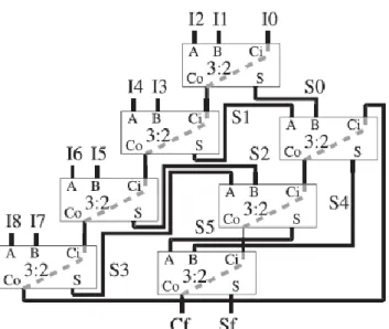
To optimize the use of the carry resources, we propose a compressor tree structure similar to the classic linear array of CSAs [24]. However, in our case, given the two output words of each adder (sum-word and carry-word), only the carry-word is connected from each CSA to the next, whereas the sum words are connected to lower levels of the array. Fig. 2 shows an example for a 9:2 compressor tree designed using the proposed linear structure, where all lines are N bit width buses, and carry signal are correctly shifted. For the CSA, we have to distinguish between the regular inputs (A and B) and the carry input (Ci in the figure), whereas the dashed line between the carry input and output represents the fast carry resources. With the exception of the first CSA, where Ci is used to introduce an input operand, on each CSA Ci is connected to the carry output (Co) of the previous CSA, as shown in Fig. 2. Thus, the whole carry-chain is preserved from the input to the output of the compressor tree (from I0 to Cf). First, the two regular inputs on each CSA are used to add all the input operands (Ii).
When all the input operands have been introduced in the array, the partial sum-words (Si) previously generated are then added in order (i.e., the first generated partial sums are added first) as shown in Fig. 2. In this way, we maximize the overlap between propagation through regular signals and carry-chains. Regarding the area, the implementation of a generic compressor tree based on N bit width CSAs requires Nop _ 2 of these elements (because each CSA eliminates one input signal). Therefore, considering that a CSA could be implemented using the same number of resources as a binary CPA (as shown below), the proposed linear array, the 4:2 compressor tree, and the binary CPA tree have approximately the same hardware cost.
In relation to the delay analysis, from a classic point of view our compressor tree has Nop _ 2 levels. This is much more than a classic Wallace tree structure and, thus, a longer critical path. Nevertheless, because we are targeting an FPGA implementation, we temporarily assume that there is no delay for the carry-chain path. Under this assumption, the carry signal connections could be eliminated from the critical path analysis and our linear array could be represented as a hypothetical tree, as shown in Fig. 3 (where the carry-chain is represented in gray). To compute the number of effective time levels (ETL) of this hypothetical tree, each CSA is considered a 2:1 adder, except for the first, which is considered a 3:1 adder. Thus, the first level of adders is formed by the first bðNop _ 1Þ=2c CSAs (which correspond to partial addition of the input operands). This first ETL produces b└Nop _ 1˥=2c partial sum-words that are added to a second level of CSAs (together with the last input operand if Nop is even) and so on, in such a way that each ETL of CSAs halves the number of inputs to the next level. Therefore, the total ETLs in this hypothetical tree are
L= ¼ log2(Nop _ 1)e, (3)
and the delay of this tree is approximately L times the delay of a single ETL.
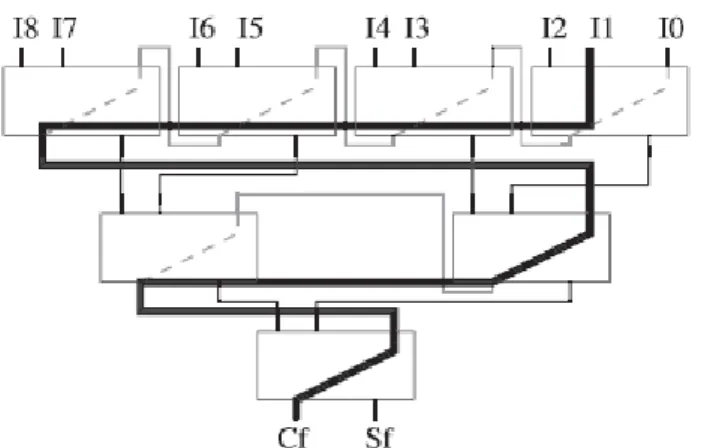
Figure 4.Critical path of the proposed 9:2 compressor tree for linear array behavior.
However, the delay of the carry-chain is comparatively low, but not null. Let us consider just two global values for the delay: dcarry, which is the delay for the path between the carry inputs (Ci) of two consecutive CSAs (see Fig. 3); and dsum, which is the delay from one general input of a CSA (A or B) to a general input of a directly connected CSA, i.e., the time taken by the data to go from an ETL to the next one (see Fig. 3). Even under this simplified scenario, it is unfeasible to obtain a general analytical expression for the delay of our compressor tree structure. On each ETL, the propagation through carry-chains and the general paths are overlapped and this overlap depends on multiple factors.
First, it depends on the relative relationship between the values of dcarry and dsum (which is associated with the FPGA family used). Second, it depends on the number of operands that affect both the delay of the carry-chain of each ETL and the internal structure of the hypothetical tree.
Even though the former could be expressed as an analytical formula, the latter cannot be expressed in this way (especially when Nop _ 1 is not a power of two). However, it is possible to bound the critical path delay by considering two extreme options. One extreme situation occurs when the delay of the whole carry-chain corresponding to each ETL (dcarry _ the number of CSAs of the ETL) is always greater than the delay from an ETL to the next one (dsum). In this case, the timing behavior corresponds to a linear array and the critical path is represented in Fig. 4. Initially, the first carry out signal is generated from I1, I2, I3 in the first CSA and then the carry signal is propagated through the whole carry-chain until the output. Thus, the delay of the critical path has two components corresponding to the generation of the first carry signal and the propagation through the carry-chain. If we characterize the delay from a general input to the carry output in the first CSA (including later routing) as dsum, then the estimated lower bound for the delay of the compressor tree is
Dlow = dsum + (Nop _ 3) * dcarry. (4) As mentioned, dsum is usually one order of magnitude greater than dcarry. Thus, the initial condition could be partially fulfilled for compressor trees with high Nop, but only in the first ETLs, because the number of CSAs on each ETL is nearly halved compared to the previous one. In fact, because the last ETL has only one CSA (ETL0 in Fig. 2), this
condition (i.e., in all ETLs) can only be completely fulfilled if dsum < dcarry, which is not possible on FPGAs.
Figure 5.Critical path of the proposed 9:2 compressor tree for tree behavior.
Therefore, although (4) is an underestimated lower bound, it reflects the behavior of the first ETLs for high Nop, as described below. The other extreme situation occurs when the delay of the carry-chain on each ETL (dcarry_ the number of CSAs of the ETL) is always less than the delay from an ETL to the next one (dsum). In this case, we obtain the hypothetical tree presented in Fig. 3. The critical path is shown in Fig. 5. It begins as in the previous case: A first carry generation from the general inputs and carry propagation through the carry-chain of the first ETL, because all internal general paths of the CSAs corresponding to the first ETL are updated in parallel and they need the carry input to generate the output signals.
However, due to the initial premise, and because sum signals arrive at the first CSAs of each ETL earlier than at the last ones, after the first ETL the critical path goes from one ETL to the next one through the general routing. Therefore, the delay of the critical path has three components corresponding to the generation of the first carry signal, propagation through the carry-chain of the first ETL, and propagation across the remaining of the ETLs. In this case, taking into account that the delay between the carry input and the
sum output (including later routing) is approximately dcarry, the estimated upper bound for the delay of the compressor tree is dsum_ the number of ETLs þ dcarry_ the number of CSAs of the first ETL, that is
Dup =[log2(Nop _ 1)e * dsum +{(Nop _ 1)/2}* dcarry. (5) This scenario is very frequent because if the delay through the carry-chain of the first ETL is less than dsum, then the next ETLs hold this condition. Thus, only the following condition
dsum >{(Nop _ 1)/2}*dcarry (6) needs to be fulfilled. Therefore, for values of Nop up to 2dsum=dcarry, the delay of the linear array compressor tree is very close to Dup. However, for greater values of Nop, the delay of the compressor tree is between Dlow and Dup, because the hypothetical structure of the compressor tree is a mix of both situations: The first CSAs form a linear array until the delay of the carry-chain in an ETL is lower than dsum, and then the remaining ones form a hypothetical tree.
In any case, the behavior of the delay related to the number of operands has two additive components:
1) A discontinuous logarithmic variation due to the number of ETLs of the hypothetical tree; and
2) A linear variation related to the propagation through either the carry-chain of the first ETL (for low Nop) or the linear array part (for high Nop).
C. High-Level Implementation
A high-level description of an FPGA design using HDL presents some significant advantages, such as portability among different families (even from different brands), easier generalization, lower error production during the design process, and so on. A disadvantage is that control over the final implementation is lost, which could produce unexpected results. Thus, the HDL code needs to be carefully selected, especially when specific inner resources of the FPGA are used. In fact, a low-level design of the basic building block, which is instantiated from the higher level circuit, is sometimes the only way to achieve efficient implementations.
Thus, the design is anchored to a specific FPGA inner structure. This is the case of the classic 4:2 compressor tree proposed in Section 3.1 for 4-LUT-based FPGA families. The linear array proposed in Section 3.2 requires the use of 3:2 counters as a basic building block. However, the commercial software tools do not support high-level CSA implementation and in any case they do not use the carry logic for the implementation of this element. In addition, no efficient low-level implementation of a 3:2counter has been reported in the literature. Thus, a different approach awaits discovery. As an example, a more detailed description of the linear array structure for an N-bit width 5:2 compressor tree .
This circuit could be implemented by connecting the FAs (which have to be designed at a low level) as shown in Fig. 6b, while carefully choosing the routing nets to guarantee the preservation of the carry chains. However, at a high level, the only way to guarantee the utilization of the specialized carry logic and the preservation of the carry-chains is by using standard CPAs as basic building blocks. In addition, this allows portability between different FPGA families. A careful examination of Fig. 6b shows that the linear array of three CSAs (see Fig. 6a) can be interpreted as an array of 3-bit width CPAs diagonally deployed (see Fig. 6c1), as highlighted in Fig. 6b for one of them. Hence,
the proposed linear compressor tree of Nop inputs could be implemented by using an array of Nop _ 2-bit width CPAs.
Although both circuits are exactly the same, we have simply provided a new interpretation at the semantic level. However, this new interpretation allows the implementation of the proposed circuit by means of standard CPAs instantiation. In this way, the most significant sum-bit of each CPA comprises the final sum-word of the compressor tree, whereas the last carry-out of each CPA comprises the final carry-word. With the exception of the CPAs at ending positions, each CPA processes 1 bit of each input operand and partial sum, varying the bit weight depending on its relative position. Let us number each CPA according to the position of its final sum bit; for example, CPA 0 is the adder, which produces the least significant bit of the final sum-word, and CPA (N-1) is the most significant one. We also number the operands added in
the linear array following their order of use, including the partial sum words.
Thus, the ith bit of each input of the CPA j adds the bits at position (j + i - Nop + 3) of the operands (2i + 1) and (2i + 2) (note that the operand 0 is connected to the carry input of each CPA). For extreme adders, these previous equations could produce negative bit positions, which should be set to zero as shown next. The use of the “generate” statement in HDL code (VHDL or Verilog) to implement these connections makes it easy to design a
parameterizable compressor tree. The CPAs from 0 to (Nop – 4) should be shorter than the regular ones, specifically from one to (Nop -3)-bit width, respectively, because the least significant part of these adders is out of range (see Fig. 6). Nevertheless, to deal with these CPAs, we keep the size of the (Nop – 2)-bit width constant by using zero padding, as the software implementation tool eliminates the superfluous hardware.
Similarly, in the most significant part, we have to use CPAs whose final sum and carry bits are out of range (from N to (N + Nop - 4), although they are required to generate intermediate results. Thus, although the implementation of an N-bit width linear array of (Nop _ 2) CSAs requires the instantiation of (N + Nop -3) CPAs of (Nop - 2) bit width, the occupied area, after eliminating superfluous hardware, is really the same in both approaches. For instance, to implement a CSA compressor tree of 16-bit width for 10 input operands (Nop = 10), 23 CPAs of 8-bit width are instantiated, but after eliminating the superfluous hardware, they occupy an area equivalent to 16 CPAs of 8-bit width or eight CSAs of 16-bit width. We should also mention that if N <Nop _ 2 is fulfilled, then all CPAs comprising the compressor tree are at ending positions (i.e., any of them will have one or more FA out of range). In practice, this fact limits the maximum delay produced due to carry propagation up to N - dcarry.
This could have a marked effect on the delay for Nop – N because it limits the linear dependence of the delay in relation to Nop, as shown in Section 4. By using this scheme based on standard CPAs, we have created a generic VHDL entity that allows us to implement a compressor tree unit with any number of inputs and any bit width. This entity could be implemented by using any typical synthesis tool and targeting any FPGA. In addition, it will take advantage of all the resources available to accelerate carry propagate addition, including those which will be developed in the future for new FPGA devices.
D. Improvement for Ternary Adders
To improve the performance of multi operand addition, the newest FPGA families, such as Virtex-5/7 or Stratix-II/V, can efficiently implement ternary addition (A + B + C = D) [44], [45], [46]. On these FPGAs, a ternary adder requires the same amount of resources as a simple 2-input adder while showing a similar speed. Since each ternary adder eliminates two operands, the number of adders required for a compressor tree is [(Nop – 1)/2, which is almost half the amount needed in the binary case. On the other hand, the number of levels is
L3:1 = [log3(Nop)], (7)
which is considerably faster than the one based on binary adders. Therefore, the ternary adder is preferred to implement
multi operand parallel addition when targeting these devices. We now present how our linear array compressor tree design is adapted to take advantage of this new resource. The ternary adder structure is based on the integration of
an initial 3:2 CSA together with a binary CPA in the same LEs [44], [45], [46]. Thus, a 1-bit element of the ternary adder has three operand input signals, one sum output signal and
two carry signals having two inputs and two outputs. One carry signal (cA), which is related to the CSA, has limited delay, i.e., the generation of this carry signal does not depend on the previous value of that carry. The other (cB), which is related to the CPA, forms a standard carry-chain.
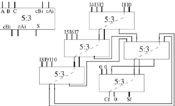
Figure 6. CS 11:2 compressor tree based on a linear array of 5:3 compressors.
Similar to how a carry-ripple adder is converted into a CSA, the ternary adder becomes a 5:3 compressor array (CA) if the carry signals are disconnected. Hence, as shown in Fig. 7, an efficient compressor tree could be created by constructing a linear array of 5:3 CAs. Similar to the previous approach (see Section 3.2), and with the exception of the first CA, where two additional operands are introduced, the two carry input signals are connected to the corresponding carry outputs of the previous adder (preserving the carry-chain constituted by cB signal), whereas the partial sum-words generated are added in the same order as they were produced after adding all the input operands.
The number of operands Nop should be an odd number and one input zero-word must be used when necessary. In addition, the last partial sum requires a final addition with
two zero-words to guarantee a zero output in the last cA signals (see Fig. 6), because only the last cB signals make up the final carry-word. Taking all these considerations into account, along with the fact that the first 5:3 CA adds five operands, the number of 5:3 CAs required to implement a compressor tree is
NAdd ={Nop – 1}/2, (8)
because two operands are eliminated by each CA. Given that a classic carry-propagate compressor tree requires the same number of ternary adders, and each N-bit width 5:3 CA uses the same FPGA resources as a ternary adder, the proposed CS compressor tree has the same area cost as its equivalent carry-propagate compressor tree. Regarding delays, a study parallel to the one performed for the 3:2 CSA array in Section 3.2 leads to a similar conclusion, i.e., the proposed array has, in
general, a linear structure followed by a hypothetical tree structure. The approximate bounds of the delay for the extreme cases (i.e., a whole linear array or a tree) are
Dlow = d5:3 +[(Nop/2)-1]* dcB (9) Dup = ( log3(Nop – 2)+ 1)* d5:3 +{[Nop –
1]/2}*dcB, (10)
where dcB is the delay corresponding to the path between the cB inputs of two consecutive 5:3 CAs and d5:3 is the delay from one ETL to the next (including the delay of signals cA), i.e., from a general input of a CA to the general input of the CA, which is connected to the sum-word of the previous CA. Once again, the delay corresponds to the addition of a logarithmic component and a linear one.
The logarithmic behavior is dominant for low values of Nop, whereas the linear behavior dominates for high values of Nop. The curve of the delay in relation to Nop is also smooth, instead of an increment by steps. These conclusions are borne out in Chapter4. This new compressor tree design (see example in Fig. 7) could also be implemented at a high-level description using ternary CPAs as a basic building block (see Fig. 6). n ternary adders of NAdd-bit width diagonally arranged are required to implement it (simplifying the extreme cases). Once again, the most significant sum-bit of each ternary adder comprises the sum-word of the compressor tree, whereas the last cB out is the final carry-word. Except for the ending adders, each ternary adder sums one bit of each operand
and partial sum, varying the bit weight depending on its relative position. If adders and bits are numbered as for the binary case (see Section 3.3), the ith bit of the ternary adder j adds the bit j +i - NAdd + 1 of the operands 3i +2, 3i + 3, and 3i + 4. Note that the operands 0 and 1 are connected to the two carry inputs of each ternary adder and negative bit
positions are set to zero.
This linear structure is efficiently mapped on any FPGA device suitable to implement ternary adders. These devices are the newer FPGAs based on 6-LUT or 8-LUT, such as Stratix-II/V for Altera or Virtex-5/7 for Xilinx. The high level description of this compressor tree could be used by any software tool capable of targeting ternary adders as
possible basic elements. In other cases, a generic ternary adder should be previously defined.
E.Pipelining
One of the main advantages of CS compressor trees is that they are very suitable for pipelining. An M-stage pipeline compressor tree of L levels of compressors is implemented simply by introducing one level of registers for each L=M levels of compressors. However, the proposed designs are defined using an array of CPAs, which complicates the introduction of registers in the linear array compressor tree. However, the proposed approach is still easy to apply in pipeline designs. The pipeline compressor tree is designed by utilizing smaller linear array compressor trees as basic building blocks, which are registered in the input or output. For instance, a two-stage 18:2 compressor tree is built by using three 6:2 linear array compressor trees.
The best size for the linear array blocks depends on the number of operands (Nop) and the number of stages (S) required for our design, but the best size could be found using
In the case, that the time requirements are known instead of the number of stages, the graphs shown in Chapter 4 could be used to find the size that best meets these requirements.
IV Implementation Results and Comparison
To measure the effectiveness of the designs presented in this project, we have developed two generic VHDL modules implementing the proposed compressor tree structures: First, the linear array implemented by using CPAs (binary and ternary) and, second, the 4:2 compressor tree using the design of the compressor presented in [28]. Both modules provide the output result in CS format and allow the selection of different parameters such as:
The number of operands (Nop), the number of bits per operand (N), and the basic building blocks (i.e., binary or ternary adder) for the linear array. For the purposes of comparison, similar modules, which implement classic adder tree structures based on binary CPAs and ternary CPAs, have also been developed. All these modules were simulated using Modelsim SE 6.3f and they were synthesized using Xilinx ISE 9.2, targeting Spartan-3A, Virtex-4, and Virtex-5 devices. A generic ternary adder module was designed following the recommendations of Xilinx [46], because this adder is not automatically supported by ISE 9.2. Furthermore, to investigate their portability, compressor trees based on ternary CPAs were also synthesized to target the Altera Stratix-II family. In this case, the ternary adders are directly instantiated at a high level. We now summarize the main results obtained in this study. 9:2 Compressor compressor11:2 (5:3) 11:2 Compressor (5:2) No.of Slices 7 10 9 No.of 4 Inputs 12 17 15 No.of IO’s 11 14 13 Power (W) 0.052 0.052 0.039 Delay (ns) 11.27 14.47 12.81
Table1. comparison results of existing and proposed design
A. Results on FPGA Families with Support for Binary CPAs
For the sake of simplicity, of the two FPGA families tested (Spartan-3A and Virtex-4), only the results corresponding to the Virtex-4 family are presented, because the results are very similar for both families. On these FPGAs, the compressor trees based on ternary adders are not efficiently implemented, and thus, we have only tested the ones based on binary adders. For purposes of clarity, let us denote as CPA tree the classic tree structure based on CPAs,
OUR array the proposed linear array structure based on 3:2 CSAs, and 4:2 tree the classic tree structure based on a 4:2 compressors. Regarding the area,the number of LUTs required by the different compressor tree structures when varying Nop from 4 to 128 operands, for 16- and 64-bit widths. With the exception of 4- and 5-operand compressor trees, which we consider separately, the area used for the three compressor trees is very similar and varies linearly with the number of operands and the bit width, as expected. Specifically, the area of CPA tree and OUR array is practically identical, whereas the 4:2 tree requires a little more area (up to 6 percent for a 16-bit width and up to 2 percent for a 64-bit width), due to the implementation of boundary bits on the 4:2 CA.
V. SIMULATION RESULTS
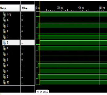
The proposed compressor gives us the better area utilization compared to the proposed one and the Xilinx Software gives us an easy way to analyze our results to get the best out of them. The simulation results of the Adder shown below.
Figure 7.Simulation results of 11:2 compressor tree.
F igure 8. Test bench simulation results of 11:2 compressor
The addition which is written in Verilog HDL is done in Xilinx Software.
V. CONCLUSION
Efficiently implementing CS compressor trees on FPGA, in terms of area and speed, is made possible by using the specialized carry-chains of these devices in a novel way. Similar to what happens when using ASIC technology, the proposed CS linear array compressor trees lead to marked improvements in speed compared to CPA approaches and, in general, with no additional hardware cost.
Furthermore, the proposed high-level definition of CSA arrays based on CPAs facilitates ease-of-use and portability, even in relation to future FPGA architectures, because CPAs will probably remain a key element in the next generations of FPGA. We have compared our architectures, implemented on different FPGA families, to several designs and have provided a qualitative and quantitative study of the benefits of our proposals.
REFERENCES
[1] B. Cope, P. Cheung, W. Luk, and L. Howes, “Performance Comparison of Graphics Processors to Reconfigurable Logic: A Case Study,” IEEE Trans. Computers, vol. 59, no. 4, pp. 433-448, Apr. 2010.
[2] J. Hill, “The Soft-Core Discrete-Time Signal Processor Peripheral [Applications Corner],” IEEE Signal Processing Magazine, vol. 26, no. 2, pp. 112-115, Mar. 2009.
AUTHORS
T.RAJYALAKSHMI has received her
B.TECH degree from JNTU Anantapur. Currently pursuing M.TECH degree from JNTU Anantapur in Sreenivasa Institute of Technology and Management Studies with VLSI system design stream and completes post-graduation by 2014.
Y.RAVIKIRAN VARMA, MTECH. Currently working as
Assistant professor in Sreenivasa Institute of Technology And Management Studies of JNTU Anantapur University in AndraPradesh.