Microstructure Evolution of Laser Repair Welded
Rene´ 77 Nickel-Based Superalloy Cast
Huei-Sen Wang
1;*, Chih-Ying Huang
1, Kuen-Sen Ho
2and Sian-Jhih Deng
11Department of Materials Science and Engineering, I-Shou University, Kaohsiung, 84001, Taiwan, R. O. China 2Department of Mold and Die Engineering, National Kaohsiung University of Applied Sciences,
Kaohsiung, 80711, Taiwan, R. O. China
This study performed repair-welding tests on Rene´ 77 Nickel-based superalloy by adopting a Nd:YAG pulsed laser technique, coupled with Rene´ 41 filler wire and various welding parameters. After welding, the microstructure evolution, crack behavior and mechanical properties of the welds were determined by a combination of scanning electron microscopy (SEM), energy dispersive X-ray spectroscopy (EDS), transmission electron microscopy (TEM), and micro-hardness test. The experimental results showed that, due to suffering from different thermal histories during the conduction of the multi-pass welding process, the microstructures within the welds had split into six zones. In terms of cracking behavior, no cracks formed in the weld fusion zone (WFZ) or the heat-affected zone (HAZ) under appropriate welding parameters; however, setting the laser energy too high resulted in weld centerline cracking or intergranular cracking in the weld fusion zone. Moreover, various types of liquation cracks may occur at the interface between the WFZ and the HAZ. [doi:10.2320/matertrans.M2011264]
(Received August 29, 2011; Accepted September 27, 2011; Published November 16, 2011)
Keywords: super alloy, welding, microstructure, crack
1. Introduction
Rene´ 77 is a precipitation hardening (0 strengthening phase-Ni3(Al, Ti)) and solid solution strengthening (Cr, Mo,
Fe, Co elements) Ni-based superalloy,1) with a designed
service temperature of between730C900C, often applied to hot gas turbine engine parts, such as vanes and blades, due to its remarkable hot corrosion resistance and excellent high temperature strength. Similar to every Ni-based superalloy cast component, some non-critical defects such as surface cracks may occur during the investment casting or after service. These cracks may substantially result in a capital loss or reduction in service life. For economic considerations, these non-critical defects may be scraped and repaired by the welding techniques.
Among the welding techniques, the Gas Tungsten Arc Welding (GTAW or TIG) welding process is widely used for surface crack repairs of the precipitation hardening super-alloy cast, due to its lower facility cost. Earlier attempts were conducted2,3)to investigate the heat-affected zone (HAZ) or interface liquidation crack after the GTAW or TIG welding process. For a superalloy containing high Al and Ti concentrations (0 formers), due to the presence of the strengthening phase, ordered Ll2 Ni3(Al, Ti) 0 phase, the
repaired cast tends to be susceptible to hot cracking in the weld metal and liquation cracking in the HAZ during the traditional GTAW or TIG repair welding process. Suscepti-bility to cracking was attributed mostly to large shrinkage stresses caused by the higher energy input of the TIG welding techniques, as a result of large amounts of rapid 0 precipitation during the cooling process. Recently, a few studies,4–6) indicated that a laser welding process, a lower energy input, high energy density, and a partial heating process, might eliminate the abovementioned problems and create a porosity-free and crack-free weldment, described
with good metallurgical bonding, low dilution, and a narrow HAZ.
However, most of those studies focused on the cracking characterization at the interface of the weld fusion zone (WFZ) and the HAZ. Very few papers have systematically discussed the microstructure evolution in the WFZ and HAZ of the laser welds. For instance, as a multi-pass laser welding process is conducted, due to the different portions of the WFZ or HAZ experiencing different thermal histories during the laser repair welding, they may display specific differences in their microstructures. The WFZ and HAZ may be further sub-divided into multiple regions. Therefore, the repaired Rene´ 77 cast under pre-selected Nd:YAG (Neodymium-doped Yttrium Aluminum Garnet) laser welding parameters was conducted in this study. After welding, the micro-structure development, crack behavior, and mechanical properties of the various regions in WFZ and HAZ were investigated.
2. Experimental Method
This experiment used a set of nickel-based superalloy Rene´ 77 turbine vanes (Table 1 shows the composition). The outer shroud was cut off, and then machined into30mm
15mm2mm test specimens for laser repair welding. The specimen surface was cleaned with alcohol prior to repair welding.
For the filler wire selection, matching the chemical composition of the base metal is generally desirable. However, for a highly strengthened nickel alloy cast (e.g., Rene´ 77), creating a small diameter laser wire with the same chemical composition as the base metal is difficult to achieve, and is not cost effective. The use of a substitute filler material for the nickel-based gas turbine vane repair has become acceptable. A general overview of substitute filler materials for the nickel-based alloy repair process can be found in Gandyet al.7)In this study, based on the suggestion from GE *Corresponding author, E-mail: [email protected]
aviation internal special print report-(No. 1536M51), Rene´ 41 (composition shown in Table 2) 0:5mm wire was selected as the filler material due to its similar composition to Rene´ 77, and because of better formability in creating a smaller diameter wire for the laser welding.
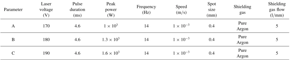
To optimize the laser pulse shape, various welding parameters was empirically investigated. Welding Condition A, B and C shown in Table 3 were pre-selected parameters in this study. Conditions A and B were selected due to those parameters produce crack-free welds. If the energy input is slightly higher than Condition B (e.g. Condition C), the crack more likely form in the weld. Furthermore, to obtain a constant welding speed, the welding process was assisted by a semi-automatic trolley. Five welding beads were deposited to conduct the repair welding process. Each welding bead was overlapped by the successive melt bead. The overlapping ratio of the track is approximately 30%. The ratio was chosen by considering the processing efficiency and surface homo-geneity. After the repair welding, the sectioned pieces were prepared by grinding, polishing, and etching with a 70% phosphoric acid electrolyte solution. The microstructures in the HAZ and WFZ were then studied by optical microscope (OM), Hitachi scanning electron microscopy (SEM) equip-ped with an energy dispersive X-ray spectroscopy (EDS) and Philip Tecnai G2 transmission electron microscopy (TEM). Vicker’s micro-hardness in the HAZ and WFZ was measured using a micro-hardness tester under a load of 100 g.
3. Results and Discussions
3.1 Microstructure of the ‘‘as-received’’ cast Rene´ 77
As shown in Fig. 1(a), in addition to thematrix, Rene´ 77 consists of typical diced cube shape0 intermetallic phases (average grain size is 0.3mm), evenly distributed within the dendrite or interdendrite area. Smaller volume fractions of carbides (see Fig. 1(b)) and -0 eutectic phases (see Fig. 1(c)) are also present. The energy dispersive X-ray spectroscopy (EDS) compositional analysis shows that carbides are predominantly the MC-type, enriched in Ti
Table 2 Composition of Rene´ 41 wire.
Element Ni Cr Mo Al Ti Co
Mass% 54.42 18.54 9.33 1.58 3.21 10.56
Element Fe B Si S C Mn
[image:2.595.43.578.83.142.2]Mass% 1.63 0.005 0.05 <0:0005 0.07 0.03 Table 1 Composition of the ‘‘as received’’ Rene´ 77 cast.
Element Ni Cr Mo Al Ti Co
Mass% 58.4 14.63 4.2 4.3 3.4 14.5
Element Fe Zr Si S C Mn
[image:2.595.46.550.184.289.2]Mass% 0.5 0.06 0.2 0.015 0.07 0.15
Table 3 Repair welding parameters adopted in this experiment.
Parameter
Laser voltage
(V)
Pulse duration
(ms)
Peak power
(W)
Frequency (Hz)
Speed (m/s)
Spot size (mm)
Shielding gas
Shielding gas flow (l/mm)
A 170 4.6 1103 14 1103 0.4 Pure
Argon 5
B 180 4.6 1:3103 14 1103 0.4 Pure
Argon 5
C 190 4.6 1:6103 14 1103 0.4 Pure
Argon 5
Fig. 1 Cast Rene´ 77 microstructure of (a)and0phases; (b) TiC carbide;
[image:2.595.332.514.330.758.2]elements. The -0 eutectic phase, typically formed from micro-segregation during the final solidification of the casting process, is observed along the interdendritic area.8)
3.2 Microstructure changes after laser repair welding
[image:3.595.63.276.264.404.2]This study conducted the repair welding process by depositing five welding beads. A new incoming melt bead overlapped a solidified weld bead in succession. After the second-pass welding, the experiment repeated the solid-ification mode of the successive weld bead. Figure 2 illustrates the microstructure change after a two-pass weld which simplifies and describes the multi-pass welding. Figure 2 also shows that due to the different portions of the welds undergoing a different thermal history during Nd:YAG
laser repair welding, they display specific differences in their microstructures, and thus, are metallurgically divided into six major regions. The first three regions, along with Region Five, are within the WFZ. Region Four is the HAZ, and Region Six is the unaffected parent metal (PM). The microstructures in relation to each of these regions are described as follows:
3.2.1 Region one
The region marked as Region One is the fusion area that is not reheated, and has a primary microstructure of the WFZ. Due to the low power of Nd:YAG laser welding, the selected welding conditions did not produce the significant difference in the morphology of solidification microstructure within Region One. Many studies9,10) have indicated that the
morphology of solidification microstructure in this area is affected by the temperature gradients (G) and grain growth rate (R) differences. The ratio of temperature gradient over grain growth rate (G/R) is called the solidification parameter. If G/R rises, the final solidified pattern tends to be planar/ columnar/cellular grains; alternately, lower G/R leads to dendrites or equiaxed dendrites. Due to the low power and high density of laser welding, higher temperature gradients (G) are present after repair welding, resulting in a higher G/R. Therefore, columnar and cellular grains dominate the solidified structures within the region. Figure 3 shows the microstructure solidification morphology within Region One as long and narrow, and the parallel line where the columnar grains are primarily growing along the heat flow direction (see Fig. 3(a)). Earlier study indicated,11) as the HAZ
liquation initiated, that a crack may propagate along the parallel line-shaped grain boundaries into the WFZ. The long columnar grain in Region One may be susceptible to
Fig. 2 Microstructure illustration of Rene´ 77 after Nd:YAG repair welding. The first three regions, along with Region Five, are within the weld fusion zone (WFZ). Region Four is the heat affected zone (HAZ), and Region Six is the unaffected parent metal (PM).
[image:3.595.124.474.481.759.2]liquation cracking or intergranular cracking, and is highly sensitive to heat input via the laser parameters; this phenomenon was observed when welding Condition C was used, as described in Section 3.3.1. In addition to columnar grains, cellular grains are present in the center or at the bottom of Region One (see Fig. 3(b)).
The product of the temperature gradient (G) and grain growth rate (R) is shown asGR,10)and is the cooling rate that governs the size of the final solidified grain. In Region One, a rapid cooling rate causes the spacing of the grains to constitute approximately 2–5mm, less than that of the original superalloy substrate (approximately 300–400mm)11)
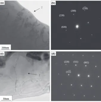
or the conventional TIG welding process (approximately 30– 50mm). Further examination of the Region One surface shows that the surface grains are even finer (about 2mm) due to the fast cooling rate (see Fig. 3(c)). Figure 3(d) shows a higher magnification of Fig. 3(b). The0phase is not clearly apparent within the grain area, even at20;000. Region One might mainly consist of the phase, supersaturated with0 phase elements (e.g., Al and Ti). To confirm this inference, this study conducted more precise transmission electron microscopy (TEM) examinations. Figures 4(a) to 4(d) show the TEM bright field images (BFIs), and the selected area diffraction patterns (SADs) of Region One when welding Condition A (the lower energy input) and welding Condition
C (the higher energy input) were employed. TEM results confirm the inference of the SEM that the region consists of the majority of theaustenite phase. Thus, from the Vicker’s micro-hardness test results (see Fig. 5), hardness in this region is softer in comparison to the HAZ and PM, which is attributed to the disappearance of the0phase in Region One. In addition to thephase matrix, several white and nano-size particles (see Fig. 3(d)) are mainly distributed along
Fig. 4 The TEM observation in Region One: (a) bright field image (BFI) and (b) the corresponding selected area diffraction (SAD) pattern ofphase in the [0011] zone axis obtained from welding Condition A; (c) bright field image (BFI) and (d) the corresponding selected area diffraction (SAD) pattern ofphase in the [11110] zone axis obtained from welding Condition C.
[image:4.595.128.468.72.418.2] [image:4.595.309.543.494.642.2]the grain boundaries, suggested by earlier study11) that the particles are MC-type carbides. This type of carbide typically forms at the end of solidification by eutectic-type reactions with thematrix, and is typically distributed along the grain boundary region.12,13)
3.2.2 Region two and region three
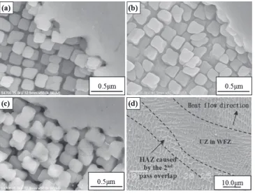
The region marked as Region Two is the unmixed zone (UZ) located in the outer extremities of Region One. Figures 6(a)–6(c) show the UZs of three welding conditions. As shown in the figures, the higher energy inputs were used, the wider UZs were obtained.
The UZ in Region Two is a boundary layer12)which shares
a similar composition with PM. Figure 6(d) shows EDS line scans (Mo composition profiles) across the fusion boundary of a Rene´ 77 welded with Rene´ 41 filler wire, suggesting stagnant melted Rene´ 77 based metal unmixed with Rene´ 41 filler wire.
The formation of the UZ can be attributed to the lower energy power of the Nd:YAG laser welding process. During the Nd:YAG welding process, the filler wire may preferen-tially absorb the majority of input energy. The remainder of the energy is sufficient to melt parts of the PM, but too weak for thorough mixing with the melted filler wire.12)
In the UZ, the phase-to-cellular grains transition, with barely visible side arms, occurs near the weld fusion line. The grains grow epitaxially from the fusion line, along the easy-growth direction to the next fusion line.
In cases of multi-pass welding, the second pass weld bead would remelt the ratio of the first pass weld bead, and repeat the first pass solidification mode. As shown in Fig. 6(d), the UZ solidification mode occurs in the second pass (Region Three in Fig. 2) remelt area. Like Region Two, the selected welding conditions did not exhibit significant difference in the morphology of solidification microstructure in Region Three; however, if the higher energy inputs were used, the wider Region Three resulted.
3.2.3 Region four and region five
The area marked as ‘‘Region Four’’ is the heat-affected zone (HAZ). For a conventional TIG welding process, which has high power, a slow cooling rate, and a wide heat exposure area, a wide HAZ can form. The HAZ in the TIG weld is further divided into several zones, such as the grain coarsen of0, the partial reversion of0, and the full reversion of0.10)
An Nd:YAG laser welding process creates a high temperature gradient, and therefore, the HAZ is not as evident under common OM; however,0grain changes in the HAZ can be observed under the higher magnification of the SEM. As demonstrated in Figs. 7(a)–7(c), the 0 grains around the WFZ produced by the selected welding conditions, are only slightly coarsened; this slightly affects the hardness in this area (see Fig. 5).
When joined by a multi-pass welding, the successive pass overlap results in a HAZ in the previous weld pass, which is marked, ‘‘Region Five’’. Similar to Region Four, Region Five from the selected Nd:YAG laser welding conditions is not clear, with only slightly coarsened grains. Figure 7(d) shows an example of Region Four obtained from welding Condition C.
3.3 Weld-cracking examination after laser repair
welding
The repair welding results show that no defects occur after repair welding in welding Conditions of A and B; however, in Welding Condition C, the use of higher power causes cracking in both the WFZ and the HAZ of Welding Condition C. Observations of cracks in the WFZ and the HAZ are detailed below:
3.3.1 Cracks at interface of the HAZ and the WFZ
In this study, the HAZ cracks involve various liquation cracks derived from the intergranular 0 phase, MC-type carbide, and -0 eutectic phases, and usually occur at the interface of the WFZ and HAZ.
[image:5.595.76.521.71.294.2]High-power density characteristics of the Nd:YAG laser welding heat or cool the alloy more rapidly compared to other traditional welding processes (e.g., the TIG welding process); non-equilibrium is obtained. It is well known11) that rapid
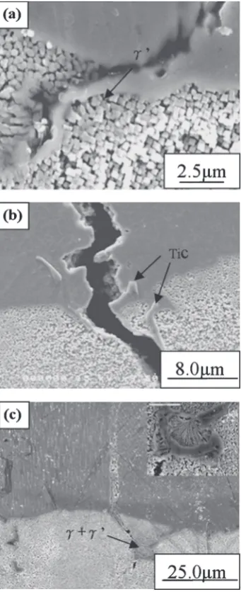
heating may increase the liquidus of an alloy to several tens or even hundreds of degrees. Especially if a higher energy input is used, this promotes even more severe localized melting of the intergranular0phase and low temperature 0 eutectics or dissolution of carbides in the HAZ. During subsequent rapid cooling, the higher heat input further induces the greater thermal strain and higher shrinkage stress by rapid solidification. As a result of these factors, the cracks originating from the intergranular 0 phase (see Fig. 8(a)), -0eutectics (see Fig. 8(b)), or carbides (see Fig. 8(c))2,3,14) located on the weld fusion line and propagating along the parallel line-shaped grain boundaries into the WFZ.
3.3.2 Examination of WFZ cracking defects
This study examined two types of WFZ solidification cracking: (1) intergranular cracking at the interface of the overlapping joint in multi-pass welding (see Fig. 9(a)); and (2) weld centerline cracking at the weld bead (see Fig. 9(b)). Research failed to discover evident liquation in either cracking patterns, and both cracks occurred at a slight higher welding power (Parameter C).
As stated in 3.2, when a new incoming welding pass overlaps a solidified weld bead, an UZ and a HAZ appear at the interface of the overlapping joint. Once solidification stress and welding thermal stress in these zones exceed the material strength, intergranular cracking occurs easily at the overlapping joint.
Weld centerline cracking at the weld bead is primarily located where the weld metal finally solidifies, as the melting point and strength decrease easily,12,13)due to lower melting
point solute buildup in this zone, as well as greater thermal stress derived from the higher welding power, which initiates cracking at the weld centerline area.
In summation, the WFZ and HAZ cracking formations are mainly the compounded results of material strength and crack driving force in the zone (including stress or strain). Therefore, less liquation, less stress buildup, or less strain during welding should reduce occurrences of cracking. Cautious choices of laser welding parameters become a significant factor. In this study, the use of Conditions A and B obtained crack-free WFZs and HAZs (see Fig. 10), though the intergranular 0 phase, or carbides, were present on the weld fusion lines of both laser welded samples.
4. Conclusions
This study performed repair welding on the Rene´ 77 by Nd:YAG laser welding under various parameters, coupled with a Rene´ 41 filler wire, and upon completion, examined the microstructure and cracking behavior. The conclusions are as follows:
(1) As the multi-pass welding process is conducted, differ-ent portions of Rene´ 77 welds undergo diverse thermal exposures during Nd:YAG laser repair welding. The welds have specific dissimilarities in their microstruc-tures, and thus, are divided into six zones.
(2) As Nd:YAG laser welding causes higher temperature gradients, the primary microstructure morphologies within Region One (the area in a solidified weld that is not reheated by the successive melt bead) are columnar or cellular. Furthermore, a faster cooling rate leads to the finer microstructures in this region after Nd:YAG laser welding.
Fig. 7 The heat-affected coarsened 0 phase in Region Four obtained from the welding (a) Condition A, (b) Condition B, and
[image:6.595.117.483.72.348.2](3) The SEM and TEM observations indicate that Region One consists of the majority of the austenite phase, and 0 precipitate appears almost absent in this zone. Thus, hardness in this zone is softer in comparison to the HAZ and PM areas.
(4) Due to the low power of the Nd:YAG laser, the HAZ is narrow, and has only a slight coarsening of the0phase or grains in this zone.
(5) When Nd:YAG laser welding power is improperly controlled, the intergranular 0 phase, carbide, or (þ0) eutectic phase, as derived from liquation cracking, can easily occur at the interface of the WFZ and HAZ.
(6) Two major WFZ cracks are in this study: the first is an intergranular cracking at the interface of the over-lapping joint in the multi-pass welding. The second is a weld centerline cracking at the weld bead. The formation of the cracks in this zone and welding power, cracking region composition, and welding stress or strain are primarily closely related.
Fig. 9 WFZ solidification cracking (a) intergranular cracking at the interface of the overlapping joint in multi-pass welding; and (b) weld centerline cracking at the weld bead.
Fig. 8 Various HAZ liquation cracking derived from (a)0phase; (b) TiC
[image:7.595.314.543.71.357.2]carbide; (c)þ0eutectic phase.
Fig. 10 The use of the welding (a) Conditions A and (b) Condition B obtained crack-free WFZs and HAZs, though the intergranular0phase,
[image:7.595.84.255.73.492.2] [image:7.595.323.530.422.739.2]REFERENCES
1) K. S. Ho and W. S. Hwang: J. Cast. Metal. Res.15(2002) 331–336. 2) O. A. Ojo and M. C. Chaturvedi: Mater. Sci. Eng. A403(2005) 77–87. 3) O. A. Ojo, N. L. Richards and M. C. Chaturvedi: Scr. Mater.50(2004)
641–646.
4) R. G. Ding, O. A. Ojo and M. C. Chaturvedi: Intermetallics15(2007) 1504–1510.
5) M. Pang, G. Yu, H. H. Wang and C. Y. Zheng: J. Mater. Process. Technol.207(2008) 271–275.
6) M. F. Chiang and C. Chen: Mater. Chem. Phys.114(2008) 415–419. 7) D. W. Gandy, G. Frederick, J. T. Stover and R. Viswanathan:ASM Materials Solutions Conference & Exposition, Energy & Utilities Program, (ASM International, St. Louis, 2000).
8) D. C. Madeleine: The Microstructure of Superalloys, (Gordon and Breach Science Phblishers, Amsterdam, 1997) pp. 33–37.
9) J. F. Lancaster:Metallurgy of welding, 6th ed., (Abington Publishing Ltd., Cambridge, 1999) pp. 193–195.
10) S. Kou:Welding Metallurgy, 2nd ed., (John Wiley & Sons, Inc., New Jersey, 2003) pp. 76–387.
11) M. Zhong, H. Sun, W. Liu, X. Zhu and J. He: Scr. Mater.53(2005) 159–164.
12) C. T. Sims and W. C. Hagel:The Superalloys, (Wiley-Interscience, New York, 1972) pp. 513–514.
13) O. A. Idowu, O. A. Ojo and M. C. Chaturvedi: Mater. Sci. Eng. A454– 455(2007) 389–397.