Multi-Subcenters Solution Search Algorithm for CFD Optimization Problems
and Its Application to Die Casting
Yoshifumi Kuriyama
1and Ken
’
ichi Yano
21Department of Electronic Control Engineering, Gifu National College of Technology, Motosu 501-0495, Japan
2Department of Mechanical Engineering, Faculty of Engineering, Mie University, Tsu 514-8507, Japan
For die-casting, various approaches tofinding the optimal control settings and optimal mold by using a computationalfluid dynamics (CFD) simulator have recently been studied and applied. However, the optimal value obtained by using a conventional CFD simulator does not consistently agree with experiment, owing to computational error. Accordingly, we analyze the problem of optimization with a CFD simulator in order to develop an optimization method that can consistently produce suitable results. To assess the effectiveness of the proposed method, it was applied to the optimization of plunger speed in die-casting. [doi:10.2320/matertrans.F-M2011831]
(Received November 29, 2010; Accepted September 7, 2011; Published January 18, 2012)
Keywords: aluminum alloy, die-casting, optimization, computationalfluid dynamics simulation, distributed control, cluster analysis
1. Introduction
Die-casting is used to manufacture a wide range of products. However, one problem with die casting for high-speed injection molding is the formation of shrinkage cavities. To avoid this, velocity control of the plunger has proved highly effective; however, analyzing the behavior of molten metal remains extremely difficult, and skilled operators of die-casting equipment typically must decide the velocity control input based on their experience and instinct. Setting of the plunger speed is also complicated by the fact that the behavior of molten metal cannot be seen as it is injected at the sleeve and into the mold.
In recent years, numerical simulators for fluid analysis based on computational fluid dynamics (CFD1)) have been used to study the behavior of afluid around an object and its thermal hydraulics. CFD is a technique based on the Navier Stokes equations, as well as on energy and mass conservation laws. Recently, for die casting, various approaches tofinding the optimal control settings or optimal mold shape by using a CFD simulator have been studied and applied.2)To obtain the optimal velocity for injection molding to avoid the formation of shrinkage cavities, optimization with CFD simulator is effective.
However, in cases where the problem has many local solutions, the most widely used general genetic algorithm (GA3,4)) is highly likely to find a local solution, whereas finding the global optimal solution is difficult. Specifically, the solution space is unstable due to the effect of the loss of significant digits or underflow error, leading to discrep-ancies between simulation and experiment. Consequently, a simulation with low computational cost does not always correspond to actual production of a high-quality product.
The aim of this study is to design a solution search algorithm that requires a smaller population tofind a solution that can be applied to the production of high-quality products. Thus, we propose a multi-subcenters solution search algorithm to compute the optimal plunger velocity for die-casting. The effectiveness of the proposed system is shown through simulation and experimental results.
2. Multi-Subcenters Solution Search Algorithm
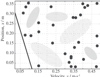
In the case of optimization with fewer search points, the location of the search point is important to derive the global optimal solution. Conventionally, search points are selected at random. However, the distribution of such search point is uneven as shown in Fig. 1, and the shaded areas in thefigure contain no search points. These areas without search points make it difficult tofind the global optimal solution with GA, leading to greater computational cost.
Thus, the search point should be located uniformly. On the other hand, to improve the convergence performance, the search points should be densely located in the area expected to contain the global optimal solution. To satisfy these criteria, we developed the multi-subcenters solution search algorithm, which has distribution control,5) convergence control and cluster analysis capabilities, where the distributed control handles the distribution of search points and the convergence control controls the density of search points. In addition, to ensure that the solution accurately corresponds to the actual production of a high-quality product, the globally stable space searching algorithm (GSSA) is applied. The
flowchart of this proposed method is shown in Fig. 2. First step, the search points are located by random, and the located
0.05 0.15 0.25 0.35 0.45
0.05 0.10 0.15 0.20 0.25 0.30 0.35
Velocity, v / m·s-1
Position,
x
/ m
Fig. 1 Setting location of search points by using random generation. Special Issue on Development of Science and Technology for Solidification and Casting Process
[image:1.595.330.522.312.459.2]points are distributed by distributed control. Second step, if there is some evaluated points around the located points, the located points are shifted by convergence control. Third step, these located or shifted points are evaluated, and changed the evaluated points. These steps are repeated until the convergence. Finally, the concentrating space of searching points and the cost function is analyzed by using the GSSA to search the globally stable space.
[image:2.595.107.225.71.337.2]2.1 Distribution algorithm
Figure 3 shows the basic concept of the distribution algorithm. The search points are moved by repulsive forces, which are represented as extending circles in thefigure.
In this distribution algorithm, each search point is first placed in a unique circle, which expands as the calculation progresses, as described by eq. (1), where R() is the radius of the circle,Raddis the value to be added to the radius, and
is the number of cycles. mq is the movement vector of the search point.
Rð þ1Þ ¼ 8RðÞ þRadd; if 8mq¼0
8RðÞ; otherwise
ð1Þ
When a circle touches another circle or the boundary, repulsive forces arise to spread the circles apart. The search points are moved by the repulsive forces in accordance with eqs. (2)(4), whereFrep is the repulsive force, q is a search point, p is another search point, Flim is the repulsive forces from the boundary, Bmin and Bmax are the upper and lower boundaries, respectively,qkis thek-th column in vectorqand n is the number of variables.
mq¼
ðqpÞ
F2
rep
; if kqpk 2R
0; otherwise
8 <
: ð2Þ
Frep ¼
1
kqpk; ðq6¼pÞ ð3Þ
mq¼
Flim; if qkRBmin;k
Flim; if qkþRBmax;k
0; otherwise
8 > < >
: ð1knÞ ð4Þ
The circles continue to expand until the movement of the search points stops. When this occurs, the search points should be distributed uniformly. Equation (5) is applied as an additional constraint on the movement of search points.
qð þ1Þ ¼ qðÞ; 8f qðÞ þ
X
mq
=
2L
qðÞ þXmq; otherwise
8 <
: ð5Þ
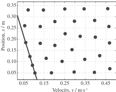
Here, fis a constraint function defined by the user, and Lis the constraint. The distribution of search points which results form using the distribution algorithm is shown in Fig. 4, where the edges of the figure indicate the upper and lower boundaries, and the inner diagonal solid line indicates the additional constraint condition. In contrast to Fig. 1, the search points are located uniformly. Thus, the distribution
Initialize points
CFD simulation
Convergence check
Yes No
GSSA
Distribution algorithm
Convergence algorithm
Finish Start
Parameter
Fig. 2 Flowchart of the proposed method.
mq
Flim
Limitation 1
Limitation 2
q
Frep
R
Fig. 3 Basic concept of distribution algorithm.
0.05 0.15 0.25 0.35 0.45
0.05 0.10 0.15 0.20 0.25 0.30 0.35
Velocity, v / m·s-1
Position,
x
/ m
[image:2.595.329.522.71.303.2] [image:2.595.330.523.342.495.2] [image:2.595.313.549.538.605.2]algorithm can ensure sufficient separation between the search points.
2.2 Convergence algorithm
[image:3.595.72.264.75.221.2]After the distribution algorithm, the convergence algorithm is executed. In the convergence algorithm, the search points converge on the basis of neighboring evaluated points. Figure 5 shows the basic concept of the convergence algorithm, where the crosses in thefigure indicate evaluated points. If evaluated points are in the vicinity of a search point, it is moved as shown in thefigure. Here,Rmaxis the effective
range of a neighboring evaluated point, and is given by the maximumRthat is used in the distribution algorithm.
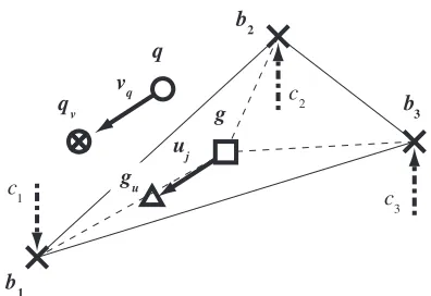
Figure 6 presents the basic concept of the convergence algorithm.
The movement of search points is governed by eqs. (6) (11). The search points of q search for nearby evaluated points that are in the circle. The center of gravity coordinateg of the selected evaluated points is calculated using eq. (7), Furthermore, the center of gravity coordinate gu that is
considered the evaluated value ofJias the load are calculated using eq. (8). Then, the movement vectoruj, which is given
by eq. (9) is calculated from the eqs. (7) and (8), wherebiis
the position vector of the evaluated point.
g¼
Xnþ1
i¼1
bi
nþ1 ð6Þ
gu¼
Xnþ1
i¼1
bi1
Ji
Xnþ1
i¼1
1
Ji
ð7Þ
uj¼gug ð8Þ
The movement of a search point is decided by the movement vectoruj, as described by eqs. (9)(11).
vq¼
0 if d¼0 or8fðqþvqÞ2= L
Xd
j¼1
uj
d otherwize
8 > > > < > > > :
ð9Þ
qv¼qþvq ð10Þ
d¼ rCnþ1 ðrnþ1Þ
0 ðr < nþ1Þ
ð11Þ
Here, qv is the moved search point, vq is the movement
vector of the search point andd is the number of combined evaluated point as given by eq. (6). If the number of evaluated points,r, is less thann+1, thend=0 is applied as shown in eq. (6).
These calculations are continued until the movement stops. The shifted points become the analyzed points of the next generation.
2.3 Globally stable space searching algorithm
The solution space formed by using a CFD simulator is unstable, and there are discrepancies between simulation and experiment; consequently, a simulation that incurs a low computational cost does not necessarily correspond to the actual production of a high-quality product. Accordingly, for the optimization, we apply the underlying notion of the Taguchi method6) to account for the error between simulation and experiment. In this way, we develop a globally stable space searching algorithm (GSSA). In this study, cluster analysis, which is a multiple classification analysis, is applied to search the globally stable space. In particular, the center of gravity of the poles and its average of cost are calculated from the evaluated search points. Specifically, the evaluated search points converge at several poles through the distribution control and convergence algorithm. The center of gravity of globally stable space is defined by eq. (12),
gc¼min E X
kgcphk2Rg
CeðphÞ
0 @
1
A;8ph2S 8
< :
9 = ; ð12Þ
Here, gcis the center of gravity of globally stable space, Eis the average of costs,phis the evaluated search point,Ce
is the cost of theph,Rgis the error criterion andSis the class
of evaluated points.
3. Application to Die-Casting Process
The effectiveness of the proposed method is tested through application to die casting. Then, the proposed method is compared with GA. As the optimization method of the die casting with CFD simulator, reference7,8) is applied.
Rmax
q
Limitation 2
Limitation 1
: Already-evaluated point
qv
Fig. 5 Basic concept of convergence algorithm.
qv vq g
uj q
gu
b1
b2
b3
c3 c2
c1
[image:3.595.317.551.80.286.2] [image:3.595.70.268.269.405.2] [image:3.595.334.549.616.652.2]At actual casting plants, the multistep velocity can be controlled and the velocity pattern, which has five phases, is derived from past studies.7,8) The plunger velocity is
expressed as shown in Fig. 7. In this study, the velocity is set to va (a=13), and the acceleration distance is set to xa (a=13), wherex3isfilling position, which takes a constant value of 0.367 m, because of the constraint of the plant.
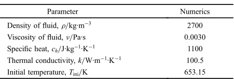
In this study, the plunger tip isflat, and hot-work die steel (SKD61) is used for the die, sleeve and plunger. An aluminum alloy (ADC12) is assumed to be the molten metal. Table 1 shows thefluid properties of ADC12. We set the die temperature during pouring to the range between 110 and 150°C (steady state) and the molten metal temperature in the melting furnace is set to between 660 and 680°C. We used Yushiro AZ7150W as a parting agent.
Our fluid analysis software is a 3D fluid calculation program that uses calculus offinite differences for handling a wide range offlows ranging fromflow of an incompressible
fluid andflow accompanied by an adjustable surface toflow of a compressible fluid flow accompanied by solidification. The free surface is calculated by using the Volume Of Fluid (VOF) method.9)The geometry of complex objects is handled by using the Fractional Area Volume Obstacle
Representation (FAVOR) method.10) Figure 8 shows an
overview of the mesh setting, and Table 2 lists the parameters for the mesh setting.
As seen in Fig. 8, the sleeve is symmetrical about the X axis. Thus, the analysis area is set as only a one-sided model to reduce the analysis time to only about ten minutes. Table 2 shows the minimum settings to perform calculations quickly and accurately, and the mesh parameter is set so that a rough
mesh is used around the start point of the sleeve because the velocity is low and the fluid is stable in the section. On the other hand, a fine mesh is used around the end point of the sleeve because the turbulence at the early stage of filling caused by collision with the sprue core in the section.
The optimization problem was defined with a cost function equivalent to the sum of the weighted quantity of air entrainment and the weighted filling time, as shown in eq. (13). The validity of eq. (13) and the parameters were verified by reference.7)
minimize:J¼wairAðva; xaÞ þwtt3þKp ð13Þ
subject to: 0:02va0:60
0:02xa0:36
0ta2:0
Ashut 3:0 ð14Þ
Here, Ais the function of air entrainment, t3is thefilling
time, xa is the acceleration distance, and wair=1.5 and wt=1.0 are weighting factors.Kp is a penalty applied each
time the conditions shown in eq. (14) are satisfied; the penaltyKp=108, which is large enough to avoid the penalty
conditions, will be added to satisfy the criteria. Also,Ashutis the volume of shutting air, not including the air surrounding the sleeve wall, plunger and molten metal, when the plunger injection is switched from low speed to high speed. Ashut is defined as shown in Fig. 9.
Three parameters are introduced to calculate the amount of shutting air.
(1) D1: Volume/opening colume of fluid in the Y cross
section.
(2) D2: Threshold of the shutting air amount.
(3) D3: Calculation time step.
V
elocity
,
v
/ m·s
-1
Time, t / s
0 t1 t2 t3
v1 v
2
v3 x1 x2 x3
[image:4.595.67.270.68.243.2]Fig. 7 Die-casting simulation model.
Table 1 Fluid properties of ADC12.
Parameter Numerics
Density offluid,μ/kg·m¹3 2700
Viscosity offluid,¯/Pa·s 0.0030
Specific heat,ch/J·kg¹1·K¹1 1100 Thermal conductivity,k/W·m¹1·K¹1 100.5
Initial temperature,Tini/K 653.15
Mesh block
Plunger
Sleeve Sprue core
Mold
Z
X
Y
[image:4.595.319.533.68.230.2]Fig. 8 Mesh settings for CFD simulation.
Table 2 Mesh parameter.
Cell size Number of cell
X-direction 0.004 20
Y-direction 0.0020.006 132
Z-direction 0.00220.0035 29
[image:4.595.307.549.284.353.2] [image:4.595.52.292.300.381.2]We usedfluid analysis software to perform calculations at each time interval specified byD3to output the cell column
fraction and the fraction of fluid in order to determine the
filling per sleeve cross section. We calculated the space volume at the back where the fraction of fluid is less than
D1©100% for the cross section, and we defined the
maximum space volume as the amount of shutting air
Ashutm3. If plunger velocity input is designed to minimize
the shutting air by using this simulator, good results can be expected for actual production experiments.
4. Validation of the Proposed Optimization
4.1 Relationship between cost function and two variables
The performance of the proposed optimization is validated for the case of plunger velocity controlled by two variables. The velocity is set as shown in Fig. 10.
Figure 11 shows the relationship of the cost function calculated using the CFD simulator for velocity and
switch-ing position. In thisfigure, brown indicates the penalty area and a lower value of the cost function signifies better quality. In this case, the global optimal solution is 0.58 m·s¹1, 0.22 m,
However, there are many local solutions around the global solution as shown in the solid circle in thefigure.
The proposed optimization algorithm is validated by conducting an experiment by using this solution space, and GA is used as a target for comparison. We seek to determine which algorithm converges more rapidly to the optimal global solution at 0.58 m·s¹1, 0.22 m, where the maximum
number of generations is 1000 and the number of trials is 10, the population size for one generation is 30. Table 3 lists the parameters for the proposed algorithm, and Table 4 lists the parameters for GA.
4.2 Results of optimization performance comparison
Figure 12 shows the results of the convergence perform-ance, where the horizontal axis is the number of trials and the vertical axis is the generation when convergence occurred. The left side bar shows the result obtained by using GA, and the right side bar is the result obtained by using the proposed Sleeve volume Fluid volume Air shut cell volume
Simulation result
Shut air volume is analyzed every time step Ashut is determined by maximum air volume
Air enclosure is distinguished by Fraction of fluid at sleeve section
Time, t / s
Shutting Air
,
Ashut
Y cross section
Fig. 9 Distinction of the shutting the air in the sleeve.
V
elocity
,
v
/ m·s
Time, t / s
0 t
v v
x xfill
tfill
[image:5.595.315.535.71.244.2]–1
Fig. 10 Die-casting simulation model.
0 0.2 0.4
0.6 0
0.1 0.2
0.3 0.4 1.5
2.5 3.5 4.5
Velocity, v / m·s-1 Position, x / m
Cost function,
J
Multimodal solution space Local solution
Fig. 11 Relationship of air entrainment with plunger velocity and switch-ing position, calculated by usswitch-ing the CFD simulator.
Table 3 Parameters for proposed method.
Parameter Numerics
Number of generation 60
Number of population 30
Additional radius,Radd 0.05
[image:5.595.303.551.315.380.2]Force from limitation.Flim 0.1
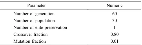
Table 4 Parameters for GA.
Parameter Numeric
Number of generation 60
Number of population 30
Number of elite preservation 1
Crossover fraction 0.80
[image:5.595.77.260.353.512.2] [image:5.595.306.551.426.504.2]algorithm. In addition, the initial locations of the search
points are same. We can see from the figure that in
comparison with GA, the proposed algorithm performs better, because the generation of convergence was lower. Furthermore, the generation of convergence of the 2nd and 6th trials by using the GA is 1000, this means that GA became trapped in a local solution.
5. Optimization of the Plunger Velocity for 5 Variables
The parameters for the proposed method are listed in Table 3, and the parameters for GA, which we compare with the proposed method, are listed in Table 4. The initial population is the same for each algorithm, allowing us to perform the calculations under the same conditions, where the calculation time per generation of the distribution and convergence is about 2 min by using the PC which has Intel Core2 Quad 2.83 GHz.
The results of calculations using the proposed method and GA are shown in Table 5.
6. Experimental Results
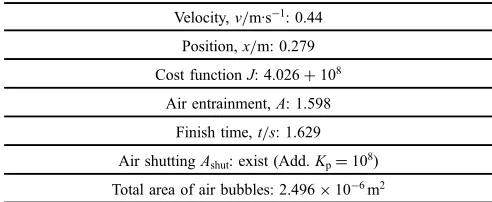
We next performed experiments at an actual die-casting plant, using the optimal velocity input calculated by the proposed method and GA. Here, from the reference,7) the experimental result by using conventional input is shown in Fig. 13. The parameter is shown in Table 6, where this plunger velocity is expressed as shown in Fig. 10.
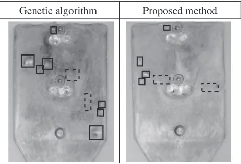
The optimized parameters calculated by using the proposed method and GA are listed in Table 7. A blister test was carried out to investigate the quantity of entrapped air. This was done by heating the specimen in a furnace, which increased the pressure of the entrapped air and formed
blisters on the surface. In a blister test, we heated specimens in a furnace to expand inside air and examine the cavity using 0.005 m plotting paper to count the number of grids with bubbles 0.001 m or more in diameter and to calculate bubble area on the casting after the blister test.
Figure 14 shows the total area on the test piece surface where air bubbles formed as a result of the blister test. Here, a solid line indicates an air bubble area over 1©10¹6m2, and a
broken line indicates air bubble area less than 1©10¹6m2. 1 2 3 4 5 6 7 8 9 10
0 5 10 15 20 25 30 35 40 45 50
Number of trials
Con
v
er
gence generation
1000
543 550
[image:6.595.99.241.68.222.2]1000
[image:6.595.318.534.70.252.2]Fig. 12 Generation of convergence for GA and proposed method.
Table 5 Performance comparison of optimization results.
Parameter Proposed method GA
Cost function,J 1.851 1.794
Air entrainment,A 0.227 0.203
Finish time,t/s 1.510 1.489
Convergence
generation 8 39
Surface (1)
Surface (2)
[image:6.595.48.291.275.350.2]Fig. 13 Experimental result by using conventional input.
Table 6 The result of the conventional input (two variables).
Velocity,v/m·s¹1: 0.44
Position,x/m: 0.279
Cost functionJ: 4.026+108
Air entrainment,A: 1.598
Finish time,t/s: 1.629
Air shuttingAshut: exist (Add.Kp=108)
[image:6.595.303.549.309.410.2]Total area of air bubbles: 2.496©10¹6m2
Table 7 Experimental results of optimization.
Proposed
method Velocity,va/m·s¹
1 Position,x
a/m
a=1 0.41 0.242
a=2 0.34 0.340
a=3 0.59 0.367
Cost function 1.851
Total area of air bubbles: 0.779©10¹6m2
GA Velocity,va/m·s¹1 Position,xa/m
a=1 0.44 0.279
a=2 0.22 0.290
a=3 0.60 0.367
Cost function: 1.794
[image:6.595.304.549.436.638.2]From Table 7, we can see that the optimal velocity calculated by proposed method resulted in less air bubble formation as well as that calculated using GA. The experimental results demonstrate that optimization with the proposed method corresponded accurately to good results in experiment.
7. Conclusion
The purpose of this study was to design a solution search algorithm that requires smaller populations to find the optimal solution corresponding to the production of a high-quality product. We proposed the multi-subcenters solution search algorithm for computing the optimal plunger velocity for die-casting. Experimental results showed that in compar-ison with GA, the proposed method could better optimize the plunger velocity in die-casting resulting in less air
entrainment. The experimental results demonstrated that optimization with the proposed method corresponded accurately to superior production by die-casting.
However, this proposed optimization algorithm take about 2 min to derive nest generation of the distribution and convergence. Thus the proposed method isn’t adequate to the optimization problem which has short time analysis.
Furthermore, in this paper, the injection speed is low until
the sleeve is filled by the molten metal, however, as
demonstrated in Ref. 11) switching the high speed injection when the molten metalfills 1/3 in the whole volume of the cavity, it can be expected the high-quality and high-cycle casting.
REFERENCES
1) P. Stefano, P. Carlo and M. Martin:JSME Int. J. Ser. B Fluids Therm. Eng.48(2005) 224228.
2) Z. Sun, H. Hu and Z. Shen:J. Mater. Process. Technol.199(2008) 256264.
3) P. Moscato:Gentle Introduction to Memetic Algorithm, (Handbook of Metaheuristics, 2003) pp. 105144.
4) T. Back and H. P. Schwefel:Evol. Comput.1(1993) 123.
5) S. Martinez, J. Cortes and F. Bullo:IEEE Contr. Syst. Mag.27(2007) 7587.
6) G. Taguchi and S. Konishi: Am. Supplier Inst.7(American Supplier Institute,1987) 835.
7) K. Yano, K. Hiramitsu, Y. Kuriyama and S. Nishido: IJAT2(2008) 259265.
8) Y. Kuriyama, S. Hayashi, K. Yano and M. Watanabe: Proc. IEEE CDC, (Shanghai, China, 2009) pp. 55565561.
9) C. W. Hirt and B. D. Nichols:J. Comput. Phys.39(1981) 201.
10) C. W. Hirt and J. M. Sicilian: Proc. 4th Int. Conf. on Ship Hydrodynamics, (1985).
11) K. Terashima, H. Nomura,et al.: IFAC Triennial World Congress, (Beijing, China, 1999) pp. 3136.
[image:7.595.52.288.71.232.2]Proposed method Genetic algorithm