Comparative Analysis of Plastic Flow and Grain Re
fi
nement in Pure Aluminium
Subjected to Simple Shear-Based Severe Plastic Deformation Processing
Dmitry Orlov
1, Yoshikazu Todaka
2, Minoru Umemoto
2, Yan Beygelzimer
3and Nobuhiro Tsuji
41Materials Engineering Department, Monash University, Clayton, Victoria, 3800, Australia
2Department of Production Systems Engineering, Toyohashi University of Technology, Toyohashi 441-8580, Japan 3Donetsk Institute for Physics & Engineering of the National Academy of Sciences of Ukraine,
72 R. Luxembourg St., Donetsk, 83114, Ukraine
4Department of Materials Science and Engineering, Graduate School of Engineering, Kyoto University, Kyoto 606-8501, Japan
In the present work, effects of loading scheme and strain reversal on structure and hardness evolution have been studied by using high pressure torsion (HPT) and twist extrusion (TE) techniques. High purity aluminium (99.99%) was processed at room temperature up to a maximum total equivalent strain of¾maxμ8 by TE, and HPT in monotonic and reversal deformation modes with strain increment¦¾max=1. Minimum subgrain sizes reached in this study were 1.6 µm for TE and 1.1 µm for HPT. It was revealed that microstructural change with straining was a common consequence of severe plastic deformation (SPD) processing and was not affected significantly by the loading scheme. Among the SPD methods used in this study, HPT in monotonic regime produced the smallest grain size, while the most homogeneous microstructure was obtained by TE due to specific vortex-likeflowfield imposed by the tool geometry. [doi:10.2320/matertrans.MD201113]
(Received July 25, 2011; Accepted September 26, 2011; Published December 25, 2011)
Keywords: high pressure torsion, twist extrusion, aluminium, microstructure, hardness
1. Introduction
One of the most efficient approaches to the production of bulk nano- and ultra-fine grained (UFG) materials is severe plastic deformation (SPD).13) As reported in the previous papers, a broad variety of metallic materials, composites and polymers has been processed, which mostly revealed mechanisms of microstructure evolution and materials behavior during and after SPD. However, knowledge of the SPD method itself still remains limited. Not all the process variables affecting microstructure development have been taken into account and clarified. Therefore, commercial applications of the SPD techniques remain very limited and their further improvement is of great interest.4) Detailed comparative studies of the effects of processing by different SPD techniques under comparable loading schemes on structure and property evolution in miscellaneous materials are of particular interest. These studies will help to optimize the existing SPD techniques and develop new.
In the present work, two SPD techniques with comparable loading schemes were selected to study the effects of processing conditions on structure and property evolution in fcc metals. The used SPD techniques are high pressure torsion (HPT) and twist extrusion (TE) that are shown schematically in Figs. 1 and 2, respectively. HPT is a technique developed from Bridgeman’s anvil apparatus.5)It was applied first to attain large plastic deformation by Smirnova et al.6) After that, many researches on different materials using this technique have been done, and HPT has been proved as the best SPD method for fundamental studies on microstructure evolution during plastic deformation to quite large strain values. Recent reviews on HPT can be found in Refs. 7, 8). Twist extrusion, on the other hand, is a relatively new SPD technique that was introduced by Beygelzimer and his research group in 1999.9,10) This technique is still considered promising, but moderately studied. HPT easily allows the variation of total accumulated
strain value as well as strain path,8,11)while other processing variables are kept the same. Therefore, it is possible to make a strain path in HPT similar to the one in TE, and carry out a direct comparison of the effects of processing on micro-structure and property evolution in aluminium between these two techniques.
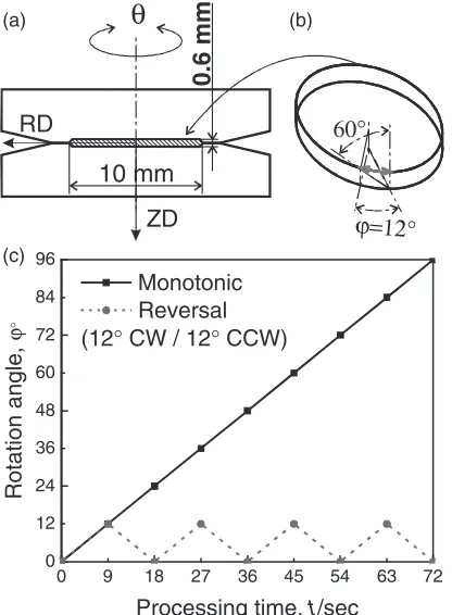
In high pressure torsion, a coin-shaped billet (typically 10 mm in diameter and up to 1 mm thickness) is placed between two anvils and compressed. After that, one of the anvils is being rotated under the pressure around the vertical axis to a specified angle as shown in Fig. 1(a). Usually it is rotated in one, e.g. clockwise, direction. In this study we used to do rotations in both clockwise/counterclockwise (CW/CCW) directions as described in details below. The equivalent strain values under HPT can be estimated from the following equation:
¾ 1ffiffiffi
3
p r
h¤ ð1Þ
whererandh are the HPT specimen’s radius and thickness, respectively; ¤is the angle of rotation in radians.
In TE processing, a prismatic billet is extruded through a “twist die”. The “twist die”has a channel with non-circular cross-section. The channel consists of straight, helical, and again straight parts along the extrusion axis as shown in Fig. 2. Repeated extrusions through this die allow the accumulation of plastic strain in the billet without any net shape change. Plastic flow during twist extrusion has been studied thoroughly in Refs. 1215) and a corresponding theoretical model to define strain distribution has been developed using upper-bound approach. For a constant angle of the cross-section rotation, 90° [Fig. 2(a)], deformation per TE pass can be controlled by the angle of the twist line slope
¢ and corresponding change in the helical part length. For this case, simplified equations to estimate equivalent strain values after TE processing have also been developed in Ref. 12) as follows:
Special Issue on Advanced Materials Science in Bulk Nanostructured Metals
¾min0:4þ0:1 tan¢; ð2Þ
¾maxp2ffiffiffi3tan¢; ð3Þ
where¢is the angle of twist line slope at the corner edge on the channel cross-section as defined in Fig. 2(b). In twist
extrusion processing, deformation is principally reversal. As it has been shown in Refs. 10, 12, 13), the deformation takes place predominantly by simple shear around extrusion axis in one direction (e.g. clockwise) upon entering the helical part of the channel, and in opposite direction (e.g. counter-clockwise) upon exiting this part. Areas of the most intensive deformation during TE processing are shown in Fig. 2(b) with red arrows.
The present work will facilitate a general understanding of SPD method, and help to optimize the existing SPD techniques and to develop new. Recent studies have shown that TE is slightly less effective in producing ultra-fine grained microstructures if compared with other SPD techniques.1518)However, results of these studies contradict to the expectations of mathematical simulations.10,12,13) Therefore, the additional aim of this work is to clarify the reasons for this discrepancy. As a representative fcc metal, 99.99%purity aluminium is selected for examination.
2. Experimental
The as-received material was 99.99%purity aluminium in the form of chill-cast and extruded bars for TE, and hot-rolled sheet for HPT experiments. Billets for TE processing 18©28 mm2 in cross-section, which is equal to the die channel shown in Fig. 2(a), and 100 mm in length were mechanically cut from the as-received bars. Coin-shaped billets for HPT processing 10 mm in diameter and 0.6 mm in thickness, as illustrated in Fig. 1, were cut by an electric-discharge machine. All the billets were annealed at 773 K and cooled in a furnace to remove deformed microstructure inherited from the preliminary processing. The microstructure of the initial billets in the as-annealed condition consisted of well defined equiaxed grains. Some structural heterogeneity in grain sizes inherited from preliminary processing was observed in the bars for TE. Average grain size of these microstructures was 280 µm. Average Vickers hardness of the annealed specimens was 18 HV.
Twist extrusion processing was done at ambient temper-ature up to 4 passes. The extrusion speed was 3 mm·s¹1. Counter-pressure of 200 MPa was applied to the billets during the processing. In this study,¢=60° [Fig. 2(b)] was used. Based on the mathematical model obtained in Ref. 12), with the specified die geometry, equivalent strain distribution in the specimen cross-section after 1 TE pass is shown in Fig. 3(a). The strain values estimated from eqs. (2) and (3) for this study are summarized in Table 1. Directions defined in Fig. 2(b) will be referred to as extrusion direction (ED), normal direction (ND) and transverse direction (TD) throughout the paper.
In HPT processing, compression force of 40 tons giving the pressure of³5 GPa was applied. The torsion was done at ambient temperature at the speed of 0.22 rotations per minute in two deformation modes: reversal and monotonic. To achieve loading scheme similar to TE, in the HPT experi-ments the deformation was imparted by simple shear around the vertical axis parallel to the extrusion direction in TE. The reversal deformation with amplitude of 12° (¦¾max=1) per step was employed to give a slope line angle of 60° at the specimen’s periphery, the same as that used for TE
(a) (b)
18 mm
20 mm
28 mm
90°
β=60°
TD
ED ND
Fig. 2 Scheme of a die for twist extrusion (TE) with the most principal dimensions (a); and scheme of the die channel (b) showing main parameter that defines net strain when other dimensions shown in (a) are fixed.
(b)
(c) (a)
ZD
θ
10 mm
RD
ϕ=12°
60°
0 9 18 27 36 45 54 63 72
0 12 24 36 48 60 72 84 96
Rotation angle,
ϕ
°
Processing time, t/sec Monotonic
Reversal (12° CW / 12° CCW)
0.6 mm
[image:2.595.67.275.74.357.2] [image:2.595.60.279.434.644.2]processing [as illustrated in Figs. 1(b) and 2(b)]. One cycle of the reversal deformation in HPT (comparable to one TE pass) was considered to be finished after 12° rotation in CW direction followed by 12° rotation in CCW direction. The processing was done up to four deformation cycles. According to eq. (1), HPT processing with the specified geometrical conditions allowed the accumulation of equiv-alent strain comparable to the strain values after TE processing. The data are summarized in Table 1.
To study directly the effect of the reversal deformation mode on structure evolution, monotonic rotations up to 96° giving the same maximum strain values as the four-cycle rotations (see Table 1) were also employed. The deformation routes used for HPT processing are shown schematically in Fig. 1(c). Directions for the HPT billets were designated as follows [Fig. 1(a)]: RD is the radial direction; ª the torsion (or tangential) direction; and ZD the direction of compression and axis of rotation parallel to ED in twist extrusion.
The characterization of microstructure was performed at different length scales by optical microscopy, electron backscatter diffraction (EBSD) analysis in scanning electron microscopes, and transmission electron microscopy (TEM).
For optical microscopy, specimens were cut in the sections perpendicular to the extrusion/rotation axes by an abrasive saw, ground and polished mechanically, andfinally anodized in Barker’s reagent. The observations were conducted in polarized light on Nikon ECLIPSE ME600L and Olympus BX60MF5 optical microscopes equipped with digital cam-eras. Macroscopicflow patterns on the whole cross-sections were reconstructed from optical micrographs of selected areas captured by digital camera. For EBSD analysis, the same sectios of the same specimens were ground mechan-ically and electro-polished in a perchloric-based aqua solu-tion. Observations were conducted on Hitachi S-4300SE and Phillips FEI Sirion field emission scanning electron micro-scopes (FE-SEM) equipped with TSL orientation imaging microscopy systems. Samples for TEM were prepared by twin-jet electro-polishing in a perchloric-based aqua solution. The TEM observations were done on Hitachi H-800 and Phillips Tecnai-20 transmission electron microscopes operat-ing at an acceleratoperat-ing voltage of 200 kV. Within the EBSD data analysis, low angle boundaries (LABs) were considered as those having misorientations 2°15°, while high angle boundaries (HABs) were²15°. Vickers hardness (HV) tests were conducted using Shimadzu HMV and Akashi MVK-E3 testing machines under an applied load of 25 g for 15 s. The hardness measurements were made on the specimens after EBSD analysis since they hadflat electro-polished surfaces, suitable for the tests. The positions of the hardness measure-ments in axial direction approximately corresponded to the half-thickness of the specimens in ZD. For every exper-imental point reported, at least three hardness measurements were carried out on the same radial position.
3. Results
3.1 Low strain level (one TE pass and equivalent HPT processing)
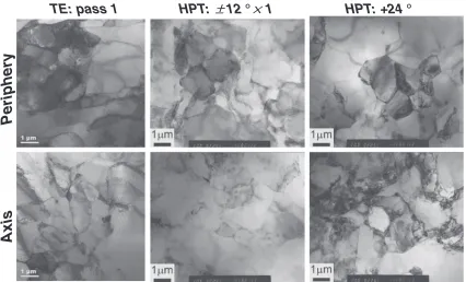
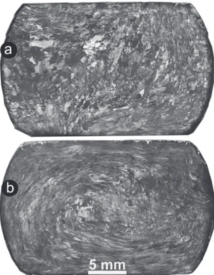
[image:3.595.62.275.71.299.2]Reversal deformation of one HPT cycle (¾max=2) leads to the formation of a structure very heterogeneous macroscopi-cally [see Fig. 4(a)]: original grains in the vicinity of the billet axis seem to remain almost un-deformed and still clearly distinguishable; peripheral areas are not the same but less clearly distinguishable. There is inhomogeneous grey contrast along the periphery so that the original grains can rarely be distinguished. Monotonic deformation for 24° rotation by HPT (¾max=2) results in less heterogeneous microstructure shown in Fig. 4(b): almost entire area of the billet cross-section has grey contrast and cannot be resolved optically; some inhomogeneity of the microstructure in tangential direction might be attributed to imperfection (e.g. axial and angular misalignments) of the HPT facility used in this study. The appearance of the grey contrast suggests intensive development of dislocation substructures with subgrain formation. TEM observations (Fig. 5) show a formation of dense dislocation walls and low angle boundaries. Depending on the radial distance from the billet center, subgrain sizes do not differ much, but most of the deformation-induced subgrain boundaries, especially in the vicinity of the torsion axis, are still diffuse. In the better statistical representation, these results are illustrated in Fig. 6 by EBSD boundary maps where LABs are plotted by grey
Table 1 Equivalent strain values reached in this study calculated from eq. (1) for HPT, and eqs. (2) and (3) for TE.
TE HPT
1 pass
4 passes
«12°©1 (24°)
«12°©4 (96°)
¾max 2.3 8.0 2 8.1
¾min 0.57 2.0 0 0
¾ave 1.2 4.8 ®*
*In the case of HPT, definition of“average equivalent strain”has no physical meaning since it is just a half value of the maximum strain and corresponds to the middle of the radius area.
TD
ND
RD
(a)
(b)
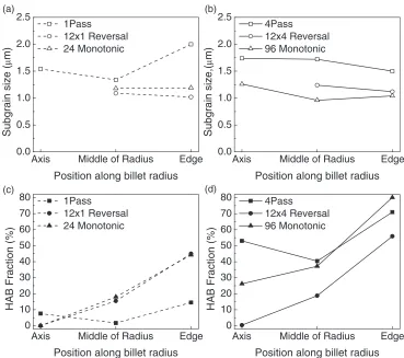
[image:3.595.45.291.378.462.2]lines, while HABs by black ones. Quantitative analysis of these data in Figs. 7(a) and 7(c) show that for both deformation modes, the differences between microstructural characteristics on this level of strain are very minor. The subgrain sizes do not vary substantially with radial distance. They are 1.1 µm for the reversal mode of deformation and slightly higher, 1.2 µm, for the monotonic [Fig. 7(a)]. Note that in the vicinity of the billet axis, the number of subgrains
surrounded by boundaries with ²2° misorientation is very small (see Fig. 6) due to very low strain in this region. Therefore, data on subgrain size in the vicinity of the billet axis is deliberately avoided in the diagrams. The fraction of high angle boundaries increases monotonically (and almost linearly) with radial distance from the billet axis toward periphery for both deformation modes [Fig. 7(c)]. For both HPT deformation modes, there is reasonable consistency
HPT:
±±
12
°
×
HPT: +24
°
TE: pass 1
Periphery
Axis
1
Fig. 5 TEM micrographs of the 99.99% pure Al at axis and periphery positions after processing by TE and HPT up to maximum equivalent strain¾maxμ2 (see more details in the text).
Fig. 4 Optical micrographs illustrating macrostructure evolution in the 99.99%Al deformed by HPT for 1 (a) and 4 (c) cycles of reversal torsion; for 24° (b) and 96° (d) of monotonic torsion.
10µm 10µm 10µm
10µm 10µm 10µm
10µm 10µm 10µm
HPT:±12°×1 HPT: +24° TE: pass 1
Periphery
Middle of radius
Axis
θ ≥15° 2°≤θ<15°
[image:4.595.54.284.69.308.2] [image:4.595.307.549.70.323.2] [image:4.595.87.513.384.642.2]between observations on all the length scales. Microstructural heterogeneity is pronounced and is proportional to the net strain gradient imposed by the loading scheme of HPT. It still reflects the significant influence of crystal orientations in the initial microstructure on this strain level. Distribution of the microstructural characteristics qualitatively corresponds to the distribution of strain from the mathematical prediction shown in Fig. 3(b).
Microstructural heterogeneity on macro-scale level is well reflected in the Vickers hardness measurements shown in Figs. 8(a) and 8(b). At this strain level (see dashed lines with open symbols in Fig. 8), for both deformation modes the hardness values almost doubled compared with the base
(annealed) condition (dotted lines). In reasonable agreement with the expectations from mathematical simulation of strain distribution, HV is lower in the vicinity of the specimens’ axes and higher at the periphery. However, the character of the hardness distribution is different. In the case of the reversal deformation, the HV values increase almost monotonically (with some scattering due to local inhomoge-neity of the microstructure) from the specimen center to the periphery [Fig. 8(a)]. In the case of the monotonic deforma-tion, the hardness is minimal near the specimen axis and also increases with the radial distance; but it reaches maximum at approximately the middle of the radius and then slightly decreases approaching the periphery [Fig. 8(b)].
Edge Middle of Radius
Axis 0.0 0.5 1.0 1.5 2.0 2.5 (a)
Subgrain size (
μ
m)
Position along billet radius
1Pass
12x1 Reversal 24 Monotonic
Edge Middle of Radius
Axis 0.0 0.5 1.0 1.5 2.0 2.5 (b) Subgrain size,( μ m)
Position along billet radius
4Pass
12x4 Reversal 96 Monotonic
Edge Middle of Radius
Axis 0 10 20 30 40 50 60 70 80
HAB Fraction (%)
Position along billet radius
1Pass
12x1 Reversal 24 Monotonic (c)
Edge Middle of Radius
Axis 0 10 20 30 40 50 60 70 80 (d)
HAB Fraction (%)
Position along billet radius
4Pass
12x4 Reversal 96 Monotonic
Fig. 7 Distribution of subgrain sizes (a), (b) and fraction of high angle boundaries (HAB) (c), (d) in the 99.99%Al after TE and HPT processing for low strain level (one TE pass and equivalent HPT processing), (a), (c), and high strain level (four TE passes and equivalent HPT processing), (b), (d). Obtained from the EBSD data.
4 2 0 -2 -4 0 5 10 15 20 25 30 35 40 45 (a) V
ickers hardness (HV)
Distance, r/mm 12°x4
12°x1 Annealed 4 2 0 -2 -4 0 5 10 15 20 25 30 35 40 45 (b) V
ickers hardness (HV)
Distance, r/mm 96° 24° Annealed 6 4 2 0 -2 -4 -6 0 5 10 15 20 25 30 35 40 45 (c) V
ickers hardness (HV)
Distance, r/mm 4 TE passes
1 TE pass Annealed
[image:5.595.113.482.68.395.2] [image:5.595.74.524.455.585.2]After one pass of TE (¾max=2.3), the optical micro-structure becomes very heterogeneous macroscopically with the peripheral areas having darker contrast than the central one [Fig. 9(a)]. This is an evidence of larger strain at the periphery of the billet than at the axial part, as comprehen-sively discussed in Refs. 15, 18). Early stages of lamellar structure formation can be seen: grains at the peripheral areas are mostly elongated although rather equiaxed and coarse grains remain in the billet center. Apart from that, all the grains have grey contrast and grain boundaries are no longer clearly distinguishable. Although some areas can still be resolved optically, the subgrain sizes cannot be measured from the optical macrographs. Observations in TEM (Fig. 5) show a microstructure with the same appearance as that after the HPT processing (cellular microstructure with diffusive subgrain boundaries), but with different distribution. EBSD boundary maps are shown in Fig. 6, and results of quantitative analysis of these microstructures are summarized in Figs. 7(a) and 7(c). The microstructural characteristics are distributed non-monotonically in radial direction after one TE pass. This is consistent with the macrostructure distribution shown in Fig. 9(a), but different from the microstructure distribution after HPT processing. Average subgrain sizes are generally larger than those after the HPT processing. Depending on the radial distance, the subgrain sizes are 1.55 µm at the billet axis, then slightly decrease and then increase again up to almost 2 µm at the billet periphery. In spite of lack of high angle boundaries at the billets axis after HPT in both deformation modes, after the TE processing there is³10%of HABs in the vicinity of the billet axis area. The fraction of HABs decreases to almost zero in the middle of the radius area and increases again up to³13%at the billet periphery. Such distribution of the microstructure
character-istics is a consequence of the netflow pattern introduced by the cross-sectional geometry of the twist channel. It is in reasonably good agreement with the mathematical prediction of the strain distribution shown in Fig. 3(a). However, the
flow pattern is strongly affected by the heterogeneous deformation of the original coarse grains.
At a low strain level, ¾max=2.3, TE processing leads to the increase in hardness similar to the HPT processing [see dashed line with open symbols in Fig. 8(c)]. However, distribution of the HV values is more homogeneous, although in the vicinity of the specimen axis HV is still³20%lower than that at the periphery. Significant scattering of the data due to local heterogeneity of the microstructure can also be seen. This distribution in hardness corresponds rather well to the dislocation substructure development described earlier. It is also in a qualitatively good agreement with the theoretical calculations of equivalent strain shown in Fig. 3.
3.2 High strain level (four TE passes and equivalent HPT processing)
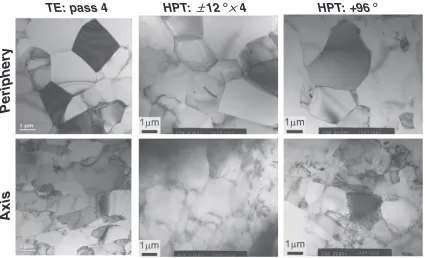
The macrostructure of the billets after 4 HPT cycles (¾max=8) is shown in Fig. 4(c). Even after this level of strain, it is still heterogeneous; but already most of the cross-sectional area has dark grey contrast and cannot be resolved optically. After the monotonic deformation by HPT for 96° rotation (¾max=8), almost entire cross-sectional area [see Fig. 4(d)] has homogeneous dark grey contrast and is not resolvable optically. An exemption is a narrow area in the vicinity of the billet axis. TEM observations (Fig. 10) show equiaxed subgrains almost free of dislocations surrounded by very well-defined boundaries at the billet periphery for both HPT deformation modes. In the vicinity of the billet axis, the subgrain sizes are nearly the same as the periphery, but the subgrain boundaries look thick with stacked dislocations nearby. This confirms lesser amount of strain introduced at the billets axis. EBSD boundary maps shown in Fig. 11 and their analysis in Figs. 7(b) and 7(d) reveal no principal change in the character of the microstructure distributions, in comparison with the low strain level. A very small variation in average subgrain sizes, within 11.2 µm, depending on radial distance can be seen in Fig. 7(b) for both HPT deformation modes. The reversal processing resulted in negligibly small change in the HABs fraction [Fig. 7(d)] at the axis area; and rather small, up to ³20%, increase in this characteristic with the radial distance to the billet’s periphery. However, the monotonic deformation by HPT leads to significant increase in the HABs fraction in the vicinity of the billet axis and almost two-times increase of this characteristic at the periphery [Fig. 7(d)]. The peripheral areas are dominated by high angle boundaries, while the billet center is still dominated by low angle boundaries (Fig. 11). Therefore, up to strain ¾max=8, a significant heterogeneity in the microstructure corresponding to the net strain gradient is retained.
After the HPT processing in the reversal regime to strain
¾max=8, the Vickers hardness distribution does not change principally, although it becomes more homogeneous [see Fig. 8(a)]. It increases but remains the smallest at the specimen axis, becomes higher with the radial distance, and from the distance of about the middle of the radius to the
[image:6.595.63.275.70.343.2]specimen periphery it becomes almost constant with some variations due to local inhomogeneity of the microstructure. On the contrary, monotonic HPT deformation to this strain level leads to principally different hardness distribution [see Fig. 8(b)]. The highest HV values can be observed at the specimen axis. With increase in radial distance, hardness decreases and approaches saturation around ³35 HV in the vicinity of the specimen periphery.
After four passes of twist extrusion (¾max=8), the material’s microstructure [Fig. 9(b)] appears as continuous development formed during the first TE pass. Much narrower lamellas than after one TE pass can be seen in most of the cross-sectional area. The lamella fibers are patterned in a clear vortex-like flow. The overall very dark contrast suggests a formation of heavily deformed micro-structure, while slightly lighter contrast in the billet central area indicates that the microstructure is still heterogeneous. The appearance of the macrostructure is much closer to the net strain distribution shown in Fig. 3(a). The subgrain sizes become so small that the pattern of plastic flow is affected only by the TE tool geometry. Separate subgrains, as well as the subgrain boundaries, cannot be resolved optically. As can be seen from EBSD data in Fig. 11 and Figs. 7(c) and 7(d), the average subgrain sizes developed after the first TE pass does not change significantly. Their distribution simply becomes more homogeneous with the average size of 1.6 µm [Fig. 5(c)]. Similar to the micro-structure evolution under the HPT processing, there is no principal change in the character of the microstructure in comparison with one TE pass. The microstructure develops mostly by increase in the subgrain boundary misorienta-tions. The HABs fraction [Fig. 7(d)] increases several times, so that in the resulting microstructure, the fraction of high angle boundaries becomes more than 50% at the center areas and slightly more than 70% at the periphery areas of the billet.
As shown in Fig. 8(c), after the TE processing to¾max=8 the average value of the Vickers hardness does not significantly increase compared with the “low strain level”. However, the trend of its distribution is opposite to that after one TE pass. At the central area, the hardness is higher, while at the periphery it is lower. This distribution is rather similar
HPT:
±±
12
°×
HPT: +96
°
TE: pass 4
Periphery
Axis
[image:7.595.88.513.71.329.2]4
Fig. 10 TEM micrographs of the 99.99%pure Al at axis and periphery positions after processing by TE and HPT up to maximum equivalent strain¾maxμ8 (see more details in the text).
10µm 10µm 10µm
10µm 10µm 10µm
10µm 10µm 10µm
HPT:±12°×4 HPT: +96° TE: pass 4
Periphery
Middle of radius
Axis
[image:7.595.50.291.380.630.2]2°≤θ<15° θ ≥15°
to the distribution after the monotonic HPT processing to the comparable strain level [see Fig. 8(b)], although average hardness value is slightly lower, 33 HV.
4. Discussion
Summarizing observations reported in the previous sections it should be noted that at early stages of severe plastic deformation, regardless of loading scheme, plastic
flow of the material is affected by two factors: flow field imposed by SPD tool geometry and local crystal orientations. Plastic flow at later stages of the processing is mostly dominated by theflowfield.
Plastic flow during the twist extrusion processing can be characterized by two principal processes: (i) formation of vortex-likeflow with large strain gradient; and (ii) stretching of structural elements of a material in one direction along with their corresponding shrinkage in orthogonal direction, and accompanied by stirring of these structural elements. The stretching of structural elements increases with subsequent TE passes. In this study, these processes are revealed by the formation of lamellar structure with specific orientation of
fibers and their stirring. The formation of stable lamellarflow pattern becomes clearer with increasing numbers of TE passes. HPT processing does not show similar behavior. In this case, no vortex-likeflow pattern is observed. Hence, the described capability for severe stirring is an unique property of twist extrusion. In addition to grain refinement, this property might be useful for homogenization of composite materials and intensification of mechano-chemical reac-tions.19,20)In accordance with mathematical simulation, under similar processing conditions (reversal HPT and TE) the stirring capability in twist extrusion leads to more homoge-neous strain distribution (Fig. 3). In this study it is reflected in more homogeneous distribution in microstructure charac-teristics (Fig. 11), as well as hardness properties, after TE processing than after HPT up to accumulated strain¾max=8 (Figs. 7 and 8).
In both TE and HPT processing, the appearance of the macrostructure (see Figs. 9 and 4 respectively) qualitatively corresponds to the theoretical strain distributions shown in Fig. 3. Irrespective of the processing method used, two processes of microstructure evolution in pure aluminium are observed: (i) development of deformation-induced subgrain boundaries, and (ii) a continuous increase in the misorienta-tions of these boundaries. Initially, the first process dominates. The boundaries form heterogeneously in the billet’s volume according to net strain gradients imposed by the tool geometry and local crystal orientations. The boundary spacing converges to lowest value. Thereafter, the formation of new boundaries saturates and the second process of the increase in the boundary misorientation becomes dominant. Low angle boundaries formed at thefirst stage, are continuously converted into high angle boundaries: namely, subgrains with low angle boundaries become grains with high angle boundaries.
This behavior is rather typical in severe plastic deforma-tion, and our results are in good agreement with other researches. The microstructure of the 99.99%purity Al was significantly refined but heterogeneous at low strain level
(¾max=2). After the processing to high strain levels (¾max=8) the subgrain boundary misorientation increased, but heterogeneous microstructure remained. As has been shown for the same grade Al2123)and commercially pure24) aluminium, as well as for other materials (e.g. Cu, Ni alloys, and steels7,8,25,26)), further torsion up to some tens of full revolutions by monotonic HPT leads to saturation in all the microstructure characteristics and, homogenization in the entire cross-section.
However, Hasegawa et al.27)have shown that in the case of reversal deformation, upon reversing the deformation direction (e.g. from CW to CCW and back), the density of dislocations decreases up to 16% and even low angle boundaries formed at the first step can be dissolved. Furthermore, Wetscher and Pippan28,29)have shown that the smallest microstructure size can be reached for the monotonic deformation, and decreasing the strain increment under the reversal deformation leads to larger subgrain size after the onset of saturation. This is quite consistent with our observations of microstructure evolution under reversal HPT: with increasing strain, negligibly small change occurs in the microstructure on the specimen axis where the strain increment is close to ¦¾=0. At the same time, significant (but still less than that in monotonic deformation) grain refinement occurs at the specimen periphery where the strain increment is close to¦¾=1. In the case of twist extrusion, microstructure distribution is more homogeneous since minimum strain increment is ¦¾=0.3, while maximum one is ¦¾=1. In this study, minimum subgrain sizes were 1.6 µm for TE and 1.1 µm for HPT.
The Vickers hardness distributions (Fig. 8) are in very good agreement qualitatively with the results by Xuet al.21) and by Kawasaki et al.22,23) for the same grade aluminium, although minor differences in absolute values of HV can be attributed to peculiarities of the experimental methods. As was shown in Refs. 21, 23), the evolution of Vickers hardness is controlled by the development of dislocation microstructures. At least in pure aluminium with very high stacking fault energy, in which recovery occurs very easily, HV increases with increasing dislocation density at early stages of deformation. It then saturates at strain level ¾μ4 when the formation of ultra-fine structure is almost saturated. Eventually it slightly decreases and remains constant with further processing, as dynamic recovery and recrystallization take place.
In our research, in the case of reversal HPT the hardness is the smallest at the specimen axis at all strain values. This is consistent with the microstructure observations indicating very little microstructure evolution at the axis with increasing strain. In the case of the monotonic HPT, HV is the smallest in the specimen center after processing to low strain level. However, at high strain level, similarly to the observations,2123) HV is the highest in the center region, slightly decreases with increase in radial distance up to approximately middle of the radius region where strain was
observed in this area; while at the specimen periphery, very clear grains almost free of dislocation and surrounded by sharp HABs are seen. Note that in our research up to strain
¾=8, scatter of the data is still significant due to local inhomogeneity, but according to Refs. 2123) it can be eliminated with further processing. In the case of twist extrusion processing, the general trend of the Vickers hardness evolution is very similar to monotonic HPT: at low strain level, the hardness is higher at the periphery and lower at the center; while at high strain level it is slightly lower at the periphery and higher at the center.
5. Conclusions
Plastic flow and grain refinement in a 99.99% purity Al under severe plastic deformation processing by high pressure torsion and twist extrusion were studied. It has been found that microstructural change in pure Al has a common trend after application of two different SPD processes (TE and HPT), and has not been affected significantly by the loading scheme. Two processes of microstructure evolution in pure aluminium have been observed: (i) development of the deformation-induced subgrain boundaries, and (ii) continu-ous increase in the subgrain misorientations.
Minimum subgrain sizes reached in this study were 1.6 µm for TE and 1.1 µm for HPT. Distribution of the average subgrain sizes was almost homogeneous, but the subgrain misorientations were heterogeneously distributed for all the processing methods. The heterogeneity in the misorientations corresponds to net strain gradients introduced by each processing method.
The hardness evolution corresponds to dislocation micro-structure development very well. It increases with imposed strain when the magnitude of the strain is small; and with increasing imposed strain, the hardness decreases due to the reduction of dislocations within subgrains.
Among the SPD methods used in this study, high pressure torsion in monotonic regime produced the smallest subgrain size, while the most homogeneous microstructure was obtained by twist extrusion due to the specific vortex-like
flow field imposed by the tool geometry.
Acknowledgements
Authors of the present work gratefully acknowledge
financial support by the Grant-in-Aid for scientific research on priority areas “Giant straining process for advanced materials containing ultra-high density lattice defects”, and that on innovative area “Bulk Nanostructured Metals”, both through the Ministry of Education, Culture, Sports, Science and Technology of Japan.
REFERENCES
1) D. Alexander:J. Mater. Eng. Perform.16(2007) 360374.
2) R. Z. Valiev, M. J. Zehetbauer, Y. Estrin, H. W. Höppel, Y. Ivanisenko, H. Hahn, G. Wilde, H. J. Roven, X. Sauvage and T. G. Langdon:Adv. Eng. Mater.9(2007) 527533.
3) A. Azushima, R. Kopp, A. Korhonen, D. Y. Yang, F. Micari, G. D. Lahoti, P. Groche, J. Yanagimoto, N. Tsuji, A. Rosochowski and A. Yanagida:CIRP Annal. - Manufact. Technol.57(2008) 716735.
4) T. C. Lowe: Mater. Sci. Forum667669(2011) 11451151. 5) P. W. Bridgman: Studies in Large Plastic Flow and Fracture,
(McGraw-Hill, New York, NY, USA, 1952).
6) N. A. Smirnova, V. I. Levit, V. I. Pilyugin, R. I. Kuznetsov, L. S. Davydova and V. A. Sazonova: Fiz. Met. Metalloved.61(1986) 1170 1176.
7) A. P. Zhilyaev and T. G. Langdon:Progress Mater. Sci.53(2008) 893 979.
8) R. Pippan, F. Wetscher, M. Hafok, A. Vorhauer and I. Sabirov:Adv. Eng. Mater.8(2006) 10461056.
9) Y. Y. Beygelzimer, V. N. Varyukhin, S. G. Synkov, A. N. Sapronov and V. G. Synkov: Phys. Technol. High Pressur.9(1999) 109110. 10) Y. Beygelzimer, D. Orlov and V. Varyukhin: 2002 TMS Annual
Meeting and Exhibition, Y. T. Zhu, T. G. Langdon, R. S. Mishra, S. L. Semiatin, M. J. Saran, T. C. Lowe. (Eds.), (TMS (The Minerals, Metals & Materials Society), Seattle, Washington, USA, 2002), pp. 297304. 11) D. Orlov, Y. Todaka, M. Umemoto and N. Tsuji:Scr. Mater.64(2011)
498501.
12) Y. Beygelzimer, V. Varyukhin, D. Orlov and S. Synkov: Twist extrusion
process for strain accumulation, (TEAN, Donetsk, 2003), p. 87. 13) Y. Beygelzimer, A. Reshetov, S. Synkov, O. Prokof’eva and R.
Kulagin:J. Mater. Process. Technol.209(2009) 36503656.
14) Y. Beygelzimer, D. Orlov, A. Korshunov, S. Synkov, V. Varyukhin, I. Vedernikova, A. Reshetov, A. Synkov, L. Polyakov and I. Korotchenkova:Solid State Phenomena114(2006) 6978.
15) D. Orlov, Y. Beygelzimer, S. Synkov, V. Varyukhin, N. Tsuji and Z. Horita:Mater. Sci. Eng. A519(2009) 105111.
16) M. Berta, D. Orlov and P. B. Prangnell: Int. J. Mater. Res.98(2007) 200204.
17) D. Orlov, Y. Beygelzimer, S. Synkov, V. Varyukhin and Z. Horita:
Mater. Trans.49(2008) 26.
18) D. Orlov, Y. Beygelzimer, S. Synkov, V. Varyukhin, N. Tsuji and Z. Horita:Mater. Trans.50(2009) 96100.
19) Y. Beygelzimer, V. Varyukhin, S. Synkov and D. Orlov:Mater. Sci. Eng. A503(2009) 1417.
20) Y. Beygelzimer:Mater. Sci. Forum683(2011) 213224.
21) C. Xu, Z. Horita and T. G. Langdon:Acta Mater.55(2007) 203212.
22) M. Kawasaki and T. G. Langdon:Mater. Sci. Eng. A498(2008) 341 348.
23) M. Kawasaki, R. B. Figueiredo and T. G. Langdon:Acta Mater.59
(2011) 308316.
24) A. P. Zhilyaev, K. Oh-ishi, T. G. Langdon and T. R. McNelley:Mater. Sci. Eng. A410411(2005) 277280.
25) R. Z. Valiev, R. K. Islamgaliev and I. V. Alexandrov:Progress Mater. Sci.45(2000) 103189.
26) A. Vorhauer and R. Pippan:Scr. Mater.51(2004) 921925.
27) T. Hasegawa, T. Yakou and S. Karashima:Mater. Sci. Eng.20(1975) 267276.
28) F. Wetscher and R. Pippan:Philos. Mag.86(2006) 58675883.