Abstract—This paper proposes an improved voltage regulation method in multi-source based DC electrical power system in the more electric aircraft. The proposed approach, which can be used in terrestrial DC microgrids as well, effectively improves the load sharing accuracy under high droop gain circumstance with consideration of cable impedance. Since no extra communication line and controllers are required, it is easily implemented and also increases the system modularity and reliability. By using the proposed approach the DC transmission losses can be reduced and system stability is not deteriorated for normal and fault scenarios. In this paper optimal droop gain settings are investigated and the selection of individual droop gains as well as the proportional power sharing ratio has been described. Experimental results validate the effectiveness of the proposed method.
Index Terms— DC power system, droop control, load sharing, voltage deviation, transmission losses.
I. INTRODUCTION
Due to the higher energy efficiency, reduced maintenance and operational costs, as well as the potential for lower environmental impact, the more-electric aircraft (MEA) concept is becoming a trend in modern aircraft design [1], [2]. MEA development introduces many challenges for the on-board electrical power system (EPS) design due to the substantially increased power demand [3] and the associated impact on the generation and distribution sub-systems. Among the possible distribution topologies, for example AC, DC, hybrid, frequency-wild and others [1], architectures with DC distribution have attracted significant research interest due to their potential advantages such as lower total weight, higher efficiency and reduced cost [4].
A MEA EPS with a DC distribution network can also easier adopt parallel operation of multiple, dissimilar electrical energy sources [5]. The expected benefits of using parallel energy sources include reduction of the total weight of the main generators and convenient integration of energy storage devices (helping to level power demands hence further reduce generators ratings and weight), as well as improving the EPS availability [6]-[9]. DC distribution systems are being widely considered not only for MEA, but also for ground vehicles, ships and terrestrial microgrids [10]-[13].
In an EPS with multiple paralleled generation sources
This work was supported by the CleanSky JTI Project, a FP7 European Integrated Project-http: //www.cleansky.eu.
The authors are with the Department of Electrical and Electronic Engineering, University of Nottingham, Nottingham, NG7 2RD, U.K. (e-mail: [email protected]; [email protected]; [email protected];[email protected]).
appropriate power sharing is of great importance since it will impact on the overall system performance. For DC networks the known load sharing strategies can be grouped into two categories: active load sharing (such as master-slave control, centralized control, circular current chain control [14]-[16]), and passive load sharing using droop control [17], [18]. The common drawback of the active load sharing methods is the dependency on the communication link between the parallel modules which is not always easy to implement in distributed power system architectures.
Droop control, as a decentralized control strategy, has been widely adopted since no communication among sources is needed, hence improving EPS modularity, reliability and reducing cost [19]-[21]. The basic idea of the droop strategy is to control the delivered amount of power (or current) by specifying that each electrical source output characteristic has a particular form of voltage drop. In a multi-source EPS with droop control the main design criteria deals with the current sharing accuracy and voltage regulation. As discussed in [19]-[21], there is a trade-off between the current sharing accuracy and the voltage regulation. A high droop gain leads to more accurate power sharing among the sources whilst the voltage regulation performance is poor, i.e. the system voltage drops significantly under large loads if the droop gain is high.
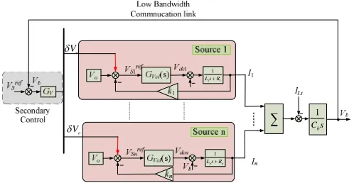
In order to maintain the system voltage for droop-controlled DC microgrids, a conventional method is to employ a secondary control to compensate the voltage drop [20] and [21], as shown in Fig. 1. Low bandwidth communication link and an additional controller are essential to restore the voltage. An enhanced droop control method with improved voltage regulation is proposed in [22] and this method adds a compensation term which is also based on the low bandwidth communication. Further, additional PI controllers are required to regulate the average voltage and current. In [23] a large droop gain is recommended to mitigate the load sharing error caused by line resistance; an average current sharing bus is then used to modify the droop characteristics such that each droop curve is shifting up with any increase in the load. As a consequence, the voltage is restored to its nominal value under any load condition. Nevertheless, the average current of parallel modules needs to be calculated and the working principle is still based on a low bandwidth communication network which increases the system cost and reduces the reliability. Therefore the voltage compensation methods presented in previous publications are based on either communication links or additional controllers [20]-[23].
An Improved Voltage Compensation Approach
in A Droop-Controlled DC Power System for
the More Electric Aircraft
1 n n
L sR
1
b
C s 1 1
1
L sR
o
V
o
V
[image:2.595.43.292.81.210.2]
Fig. 1. Conventional secondary control for voltage restoration in DC microgrids.
In contrast to conventional voltage restoration methods, an improved voltage compensation method in EPSs without communication link is proposed in [26], however this study is limited to a system with pure tightly regulated power electronic converters or motor drives which often behave as constant power loads (CPLs) [24]-[25]. This paper extends this voltage compensation method for droop-controlled EPSs with mixed load types, including CPLs and resistive or constant impedance loads (CILs). The proposed compensation method has the following advantages:
load sharing accuracy is guaranteed and improved
under higher droop gain
voltage regulation can be realized even if the
compensation gain cannot be quickly updated
performance of the current sharing and voltage
regulation are also good under most fault conditions
system stability is not compromised and guaranteed
The total load current and output current for each
source is reduced, hence the efficiency of the system is increased due to reduced losses in lines and sources
For the machine-based generation system, the resistive
loss in the machine is reduced and the overload capacity is increased to some extent.
In a voltage droop-controlled system the selection of droop gain is critical as it not only impacts on the load sharing accuracy but also influences the voltage regulation. Droop settings based on the reduction of generation cost in microgrids are discussed in [27] and [28]. In [29], an optimal power flow (OPF) of a meshed AC/DC microgrid in the voltage source converter (VSC) based high voltage DC (HVDC) transmission network is proposed and the droop gain settings are optimized to meet the requirement of line losses minimization. Similarly, a hierarchical control architecture is employed and the OPF based secondary control is used to minimize the transmission loss in the MTDC grids [30], [31]. In [32] the droop gain for each terminal in MTDC grids is obtained through a cost function which takes into account the power flow error, voltage deviation and transmission loss. However, transmission loss reduction based droop gain setting strategies for multi-generator based single bus DC EPSs have not been fully investigated with the voltage restoration method. It is of interest to design proper droop gains to minimize the transmission loss when the DC terminal voltage restores to the nominal value. To fill in this gap, this paper
considers optimal droop gain selection for parallel modules based on minimization of line losses within the proposed voltage compensation approach.
The main contributions of this paper include an enhanced voltage compensation method for droop-controlled EPS that does not require extra controllers and communication between the sources, as well as a method for optimal droop gain
selection based on the criteria of transmission loss
minimization. Based on the proposed voltage compensation method, the droop gain can be set to a higher value which results in more accurate and faster dynamic response of load sharing. Since the CPL may lead to system oscillation or instability, the sensitivity analysis has also been performed in the paper.
The paper is organized as follows. Section II presents the studied EPS architecture and describes the system control. Section III introduces the proposed voltage compensation method and analyses the effectiveness of this method under normal and faulty scenarios. The transmission loss reduction droop scheme is discussed in Section IV. The optimal main bus droop gain and individual droop gain setting are analysed in this section as well. Section V discusses the stability analysis of the proposed method under normal and fault scenarios. Experimental validation is reported in Section VI where the performance of the proposed compensation method is demonstrated. Finally, the conclusions are drawn together in Section VII.
II. SYSTEMARCHITECTURE
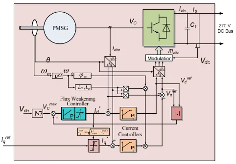
A potential candidate for a future MEA EPS architecture with multiple paralleled sources is shown in Fig. 2. It is assumed that the main generators (powered by engine) are
permanent magnet synchronous machines (PMSGs) G1-Gn.
controlled by pulse-width modulated (PWM) active rectifiers
(ARs)AR1-ARncorrespondingly. All the generators are
vector-controlled and at high speeds are operated in flux-weakening mode. The corresponding control structure and design are detailed in [33] and shown in Fig. 3. The main EPS bus is
270V DC and includes a capacitor bank Cb. The EPS loads
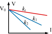
include power-electronic interfaced loads and resistive loads. Depending on the control strategy, the EPS sources (PMSG-AR systems) can be controlled either as a voltage source or a current source [34]. The control scheme for voltage-mode droop controlled PMSG-AR is shown in Fig. 5(b). As expressed in (1), the DC voltage reference is generated according to the branch output DC current using V-I droop characteristic shown in Fig. 5(a),
*
dc o dc
V
V
kI
(1)The current-mode droop control scheme is shown in Fig. 4(b) with the current reference derived from the specified droop characteristic based on the DC voltage measurement (see Fig. 4(a)). The target of current-mode system is to control the DC current to follow the reference value computed from droop characteristic shown below,
* o dc
dc
V V
I
k
The two major problems in droop-controlled system are establishing desirable load sharing ratio accuracy between the sources, and ensuring the appropriate voltage regulation. Current (load) sharing in steady state is given by [34]:
1
1 1
i i
i
I k n
I k n
(3)
whereniis the weighting proportion of theithsource currentIi
with respect to the 1st source current I1, Ri is the ith cable
resistance,kiis the droop gain. In practice, this ratio is affected
by cable impedances as shown in (4),
1 1
1 1
i i
i i
I k R n
I k R n
(4)
It can be seen from (4) that the accuracy of load sharing will be deteriorated by the cable impedance. In order to
mitigate the adverse effect of cable influence, two approaches can be employed here. One is to modify the droop gain according to the actual cables resistances as follows:
1 1 1
( )
i i
i
n
k k R R
n
(5)
However, this approach will require knowledge
(measurement) of the cable impedance. Taking into account that the cable resistance is not constant during EPS operation and highly depends on environmental conditions, this approach faces certain practical limitation.
An alternative solution is to set a relatively large droop gain
(ki>>Ri) such that the impact of R-terms in (2) becomes
negligible. The current sharing accuracy will be improved however the voltage regulation will be high and unacceptable for some applications. For example, MEA EPS are subject of power quality standard MIL-STD-704F [35]: for 270V DC
{
m
e
m
2 2
max ref ref
q s d
[image:3.595.295.536.85.253.2]I I I
Fig. 2. The multi-generator power system architecture candidate. Fig. 3. Control block diagram of a PMSG fed by a AR.
[image:3.595.54.260.87.249.2](a) (b)
Fig. 5. Voltage-mode droop control scheme. (a) Voltage-mode droop curve. (b) Voltage-mode droop control scheme.
(a) (b)
[image:3.595.305.540.431.530.2]system the voltage range is set from 250V to 280V in steady-state. Hence, the droop characteristic should be stiff enough to maintain the bus voltage above 250V under heavy loading conditions. This means a compromise between the power sharing accuracy and voltage regulation in droop controlled systems should be found.
III. PROPOSEDVOLTAGECOMPENSATIONMETHOD
A. Global Voltage Droop Gain
This Section introduces an improved voltage compensation method that simultaneously provides good load sharing accuracy and low (or no) voltage regulation, without introducing additional controls. Since all the sources in the example EPS are droop-controlled, the V-I characteristic of the main bus will also be a droop as proved below. For any source branch one can write the following:
1( 1 1) 2( 2 2)
... ( )
b o o
o n n n
V V I k R V I k R
V I k R
(6)
whereI1,I2, …Inandk1,k2, …knare the branch current and
the droop gain, respectively;Vorepresents the nominal voltage
(270V in this study) andVbis the main bus voltage.
Hence, one can derive the total load current:
1 2
1
1
... ( )
n
Lt n o b
i i i
I I I I V V
k R
(7)Reformatting (7) results in:
1
1 1
b o Lt n
i i i
V V I
k R
(8)
From (8), the droop characteristic of the main bus can be defined by the following gain:
1
1 1
t n
i i i
k
k R
(9)
This value is referred to as a global droop gain kt. Assuming
the high individual droop gains are applied (i.e.ki>> Ri), the
influence of cable impedances in (9) can be neglected, hence the global droop gain can be considered as follows:
1
1 1
t n
i i
k
k
(10)
The relationship between global droop gain and individual droop gains is shown by Fig. 6. It can be seen that the global droop gain is always smaller than individual droop gains, hence the main bus voltage drop will be reduced if more sources work in parallel.
B. Proposed Compensation Method
According to the droop control principle, the DC bus voltage will reduce with the increase of load power/current. As discussed above, in multi-source EPS high droop gains results
in better power sharing accuracy between the sources, however leads to a large voltage drop under heavy loads; the latter might be unacceptable in certain applications. In order to address the issue an enhanced voltage compensation method that adjusts the sources references according to the feeder current (i.e. load) using feed-forward link is proposed, as shown in Fig. 7 for voltage-mode and in Fig. 8 for current-mode droop-controlled system. The main bus voltage under
the feedforward action restores to its nominal value
autonomously. The GVcl(s) in Fig. 7 and GCcl(s) in Fig. 8
represent the closed loop voltage control dynamics and current
control dynamics for the ith converter in voltage-mode and
current-mode controlled systems, respectively. A feed-forward term is added to the voltage reference in each module, this correction can be expressed as follows:
Lt t
V I k
(11)
where ILt is the total load current. As one can see, only the
feeder (load) current needs to be measured and no DC voltage controller is required.
In typical MEA EPS, the variety of loads can be related to three categories, namely: CIL, CPL, and CCL (constant current load). Resistive loads are regarded as CILs because the impedance is invariant to any changes in voltage and/or current. Any change in bus voltage will cause a proportional change in such load current. For CPL, the change of load current is reciprocal to the change of the bus voltage, the load current reduces with the increase of bus voltage.
The working principle of the proposed compensation method under different load types is shown in Fig. 9. The main bus V-I characteristic is represented by the straight line with
slopekt. Under conventional droop control, the operating point
is shown asop0. After the proposed voltage restoration method
is implemented, in case of CPL the operating point moves to
op1. It can be seen that the DC current atop1is smaller than
op0, which indicates that the proposed method can reduce the
total load current in EPS with CPLs. For the CCL case, the
operating point will go to op2 where the current is kept the
same as in initial operation pointop0. If the proposed method
is applied for CIL, the EPS new equilibrium point will be at
op3. In all cases, under the action of the proposed feedforward
link, the DC bus voltage is restored to the reference value.
Hence, at any load characteristics, the voltage deviation (ΔV) caused by the traditional droop characteristic is compensated; the terminal voltage is properly restored however the droop slope is kept, which guarantees the load sharing performance.
[image:4.595.373.483.93.166.2]C. Fault Scenario
If the outage of one or multiple sources occurs in EPS, the remaining ones will share the load power according to their individual droop constants. The proportional power sharing among the remaining sources is still ensured as the individual droop gains for the rest of working sources are invariant. If the
feed-forward gainktfollowing the fault is updated according to
the after-fault conditions, the bus voltage will restore to its
nominal value. Ifktcannot be updated or is updated slowly, the
droop gain of the lost source still participates in the global
droop gain (kt) calculation, this will result in feedforward link
with a smaller kt value according to (10) and the introduced
compensation will not restore the bus voltage not to its nominal value but to some smaller one: in any case, the voltage deviation will be reduced when applying the proposed approach.
D. Effect on PMSG-based System
If the proposed voltage compensation method is applied in the DC power system fed by PMSGs operating in flux weakening mode as discussed in Section II, the compensation method will effectively reduce the stator losses and increase the overload capacity, as detailed in this subsection.
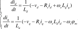
The dynamic equations for PMSG in the dq frame are as
follows [36]:
1
( )
1
( )
d
d s d e q q
d
q
q s q e d d e m
q
di
v R i L i dt L
di
v R i L i dt L
(12)
wherevd,vq:d- andq-axes components of stator voltage;id,iq
: d- and q-axes stator currents; Ld ,Lq : d- and q-axes
corresponding inductances; Rs: stator resistance; φm: flux
linkage of permanent magnet; ωe: rotor electrical angular
velocity.
In this example a surface-mounted PMSG is used, thus the
machine inductances in thed-axis andq-axis are identical (Ld=
Lq = LS). Maximum phase current Icmax is defined by the
inverter and machine ratings; maximum voltage Vcmax is
dependent on voltage in DC-link and on selected modulation method. The voltage and current limitations can be considered [33]:
2 2 max
2 2 max
( ) ( )
e s q s d m c
d q c
L i L i V
I I I
(13)
These limits can be represented by circles as shown in Fig. 10; the current limit circle center is at origin and the voltage limit
circle are centered with respect to the point (-
φ
m, 0) and theirradius isVcmax/ωe[37]. Fig. 10 shows the effect of the proposed
voltage restoration method on PMSG performance.
For the given generator speed, the voltage limit circle radius is proportional to the converter AC voltage which in its turn is proportional to the DC voltage. Hence, the voltage circle will become larger if the proposed voltage compensation method is employed. The threshold AC voltage for entering onto flux weakening is increased correspondingly under the same load power and generator speed. As a result, less negative defluxing
current (Id) is needed: as shown in Fig. 10, the equilibrium
point changes toE2formE1under the proposed compensation
method. Hence, the stator current of the PMSG decreases and the resistive losses within the machine reduce. In addition, the proposed restoration approach is beneficial for the machine
overload capacity since moreIqcan be applied for the account
1
n n
L sR b
V
1b
C s
1 1
1 L sR b
V
t
k
t
k
Fig. 7. Proposed voltage compensation method for voltage-mode droop controlled converters.
1 1
C s 1
1 /k 1 1
1
L sR
1
n
C s
1 /kn
1
n n
L sR
1
b
C s
[image:5.595.59.275.84.201.2]Fig. 8. Proposed voltage compensation method for current-mode droop controlled converters.
Fig. 9. Operating mechanism of the proposed method.
[image:5.595.60.292.236.343.2] [image:5.595.327.511.252.368.2] [image:5.595.97.232.664.714.2]of reduced Id, or more EPS load can be supplied before the inner current loop of PMSG control (shown in Fig. 4 and 5) hits the limit.
Thus, it should be pointed out that the proposed voltage compensation method can not only reduce the bus voltage deviation maintaining good load sharing accuracy, but increase the overload capacity of the PMSG-based generation system as well.
IV. TRANSMISSIONLOSS-BASEDDROOPSCHEME
As discussed above, the proposed compensation method can reduce the total CPL current (as shown in Fig. 9) and the currents in individual branches. Hence, this approach can minimize the transmission losses and as a result, increase the system efficiency compare to conventional droop control method. This section discusses the optimal droop settings based on transmission losses reduction applying the proposed method
As shown in Fig. 9, when the compensation is introduced, the total load current increases under CIL but reduces under CPL. Since the current of CCL does not change after the compensation, only CIL and CPL considered in further
discussion. The total load current before compensation ILt1is
written by (14),
1 1
1
cpl b Lt
res b
P V I
R V
(14)
where Pcplis the CPL power, Vb1 is the bus voltage without
compensation andRresis the CIL resistance.
As the proposed method is activated, the bus voltage
restores to its nominal value (Vo) and the total load currentILt2
can be re-calculated as follows:
2
cpl o Lt
res o
P V I
R V
(15)
Following aforementioned discussion, the compensation
method will increase the CIL current but reduce the CPL current.
A. Optimal Global Droop Gain Setting
In order to analyse the transmission losses, the current difference between (14) and (15) can be found:
1 1
1 2
1
( b o)( b cpl)
Lt Lt
b res o
P
V V V
I I
V R V
(16)
However,Vb1is less thanVo:
1 1
b o t Lt
V
V
k I
(17)Thus, the following condition should be satisfied to ensure the load current is reduced after the compensation:
1 cpl 0 b
res o
P V
R V
(18)
From (14) and (17), the bus voltage before compensation can
be obtained (Vb1):
2 2 1
4 ( )
2( )
res o t cpl res t res o res b
t res
R V k P R k R V R
V
k R
(19)
Global droop gain settings can be optimized by solving (18) and (19) yielding
2 2
2 2 2
2
2
2 2
, 3
, 1
2 2
,
1 0
2 2
o o
cpl
res res
cpl res o res cpl res res o
t
o cpl
cpl res
o cpl
res
cpl res res o
res t
cpl
V V
if P
R R
P R V R P R R V k
V P
P R
V if P
R
P R R V R
k
P
(20)
IfPresis defined as the power of CIL at the nominal voltage as
in
2 o res
res V P
R
(21)
then a ratio “r” between the power of CPL and CIL can be
defined here:
cpl
res
P r
P
(22)
As a result, the global droop gain can be expressed as follows:
1
1, 1,
3
, 1
1 1 0 ( 1 1)
( 1 1) 2
1 2
res
res t
res t
if r if r
R R
r k
R k r
r r
(23)
The minimum total load current can be achieved based on the following global droop gain settings, which can be regarded as
the optimal droop gainkt_optimal
_
1 1
, ( 1 1)
3 2
res cpl res t optimal
R
if P P k
r
(24)
From (24) it can be concluded that the optimal droop gain cannot be obtained if the CPL power is less than one third of CIL power. As the proposed compensation method restores the DC bus voltage, the CPL current reduces. However, the CIL current increases due to the increase of DC voltage. If the CPL power is too small, the current decreases less than the increase due to CIL response, hence the combined load current is increased. Thus, the prerequisite for the optimal droop gain to be obtainable is that the CPL power needs to be higher than one third of CIL power. In practical MEA EPS with multiple motor drives and other loads tightly controlled by power electronic converters this condition is easily satisfied.
B. Influence of Power Sharing Ratio
global droop gain. To find the optimal individual droop gains, line losses analysis of the individual droop gains is required.
Assume that n modules are working in parallel, the ith
module shares ni(ni< 1) part of the total load. Hereniis the
weighting factor of the output current ofithsource. The current
sharing ratio among the parallel modules can be expressed as:
1 2 1 2
1 2 : : : : : :
: 1
n n
n
I I I n n n
Condition n n n
(25)
A typical MEA EPS geometry is symmetrical, hence both generators are on the same distance from the power distribution centre and the cable lengths can be assumed to be
identical (i.e. the resistanceRcfrom each source to the load is
identical). Therefore, the optimization task can be formulated:
2 2 2 2
1 2
1 2
min( ) min[ ( )]
1
Lineloss Lt c n
n
P I R n n n
n n n
(26)
By solving (26), the losses can be further minimized on the
condition that each module shares the load current
equivalently, i.e., (n1 = n2=…= nn). Hence the individual
droop gains can be optimized:
_
_ * _
1 /
t optimal
i optimal t optimal
k
k n k
n
(27)
wherenis the number of parallel modules in the system.
Summarizing, the proposed voltage compensation method can reduce the transmission losses of the system in presence of large enough portion of CPL in a total load power budget. With the proposed approach, a high droop gain can be applied for each paralleled module and as a result, the power sharing is guaranteed without any additional controls.
V. STABILITYANALYSIS
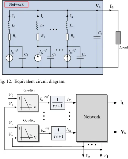
Since CPLs may result in oscillation and even instability for the system, system stability is of concern with the proposed voltage compensation method. This section will investigate the transient behaviour and system stability of the proposed method. Based on the equivalent circuit diagrams shown in Fig. 12 using a first-order lag to represent the control dynamics (see Fig. 13), the corresponding state space model in small-signal manner and state variables are shown as below:
1 2 1 2 1 2
( b, , , , n, , , , ,n s,s, ,sn T)
Compen
x A x
x v v v v i i i i i i x A x
(28)
whereAandAcompendenotes the state matrix of the system with
conventional droop control and the system with proposed
voltage compensation method respectively; vb stands for the
bus voltage; v1, v2 ,…, vnrepresents the local DC terminal
voltage;i1,i2,…,instands for the branch current;is1,is2, …,isn
indicates the source current. The details of the state matrix are shown in Appendix.
Comparing the eigenvalues of the matrixAandAcompen, Fig. 11
shows the dominant eigenvalues of twin and three sources
operating in parallel under the load of 2 kW CPL and 47 Ω
CIL. It can be seen that the eigenvalues of the system with proposed method are almost identical with previous ones and one eigenvalue slightly move towards the left. It reveals that the voltage compensation method does not compromise the stability of original system.
The fault scenario is also taken into account in the three source paralleling system. When the contingency of one source
(a)
[image:7.595.58.272.90.355.2](b)
Fig. 11. Dominant Eigenvalues of parallel-source paralleling system. (a) Twin sources. (b) Three Sources.
-320 -300 -280 -260 -240 -220 -3
-2 -1 0 1 2 3 4x 10
4
Pole-Zero Map
Real Axis (seconds-1)
Im
ag
in
ar
y
A
xi
s
(s
ec
on
ds
-1)
Conventional Control With Compensation
-350 -300 -250 -200 -150 -3
-2 -1 0 1 2 3
x 104 Pole-Zero Map
Real Axis (seconds-1)
Im
ag
in
ar
y
A
xi
s
(s
ec
on
ds
-1)
Conventional Control With Compensation
R1
Load L1
I1
C1
R2 L2
I2
C2
Rn Ln
In
Cn
Cb
Vb IL
Network
IS1ref IS2ref ISnref
Fig. 12. Equivalent circuit diagram.
1 1
s
1 1
[image:7.595.60.272.90.219.2]s
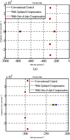
[image:7.595.367.501.100.373.2]happens, the desired compensation gainktshould be computed based on the left two active sources. However, if the desired global droop cannot be updated in real time, the droop gain of
the lost source still participates in the global droop gain (kt)
calculation, As a result, a smaller kt, which can be defined as
[image:8.595.361.497.94.367.2]the out-of-date compensation, is used in the feedforward link shown in Fig. 8. Fig. 15 shows that the eigenvalues of the fault scenario. It does not show so much difference with the out-of-date droop gain in terms of stability, which indicates that the system stability is still ensured with out-of-date compensation.
Fig. 15shows the eigenvalues loci for varying global droop gain when the proposed compensation method is activated. It can be seen that dominant poles will move towards the RHP as the global droop gain increases, which indicates that the system stability is degraded with the increase of the global droop gain. However, system stability is still guaranteed with
large global droop gain settings. Therefore, it also
demonstrates the feasibility of the proposed voltage
compensation method under large droop gain settings.
As a summary of this part, the proposed compensation method does not deteriorate the system stability under normal scenario and fault scenarios. Even if the global droop gain is not fully updated, the stable operation is still guaranteed with the proposed method.
VI. EXPERIMENTALVALIDATION
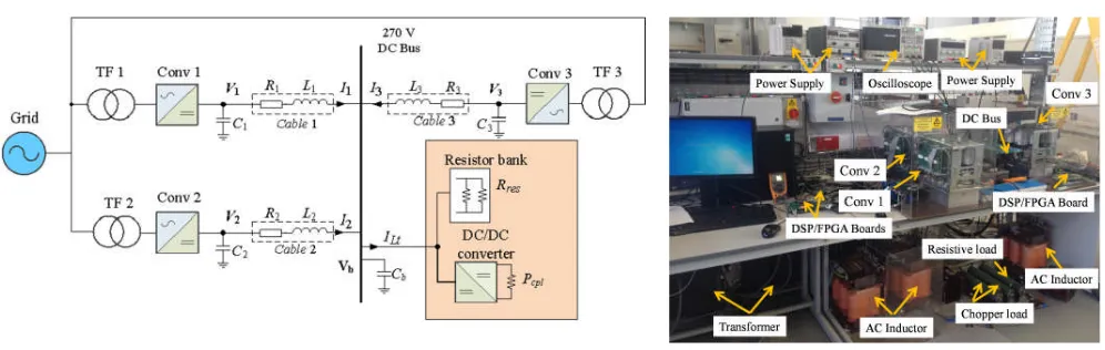
To support the analysis in the previous Sections, a potential DC EPS with three power converters working in parallel, as shown in Fig. 16, was built in the lab. The three-phase input voltage for each module is isolated through a step down transformer (415 V/160 V) in which primary side is connected to the 415 V (line-to-line RMS voltage) utility grid. A DC/DC converter (buck converter) with resistor is tightly regulated in constant power mode. The topology considered in this section can be viewed as a fundamental subsystem of more complex MEA EPS. As shown in Fig. 17, a prototype EPS consisting of three parallel active front-end converters (Semikube) has been constructed to validate the performance of proposed voltage compensation method. The experimental system parameters are listed in Table I.
A. Unequal Power Sharing Case(Case1)
First of all, pure CPL is used as the load to justify the effectiveness of the proposed method. Thus, the resistor bank is fully used as the load of DC/DC converter which behaves as a CPL. If a small droop gain is applied, the voltage drop at the main bus is small even at heavy loads due to the stiff global droop characteristic. However, the current sharing ratio is not exactly 1:2:1 as desired because the cable resistances influence
the accuracy of the current sharing, according to
Error! Reference source not found.. Therefore, the individual droop gain for each converter is 8, 4 and 8 respectively to
satisfy the conditionki>>Rc. The global droop gain, according
to (10), becomes equal to 2. Fig. 18 shows the effect of the proposed voltage compensation method of the test rig with
pure CPL (4 kW). It can be seen that beforet= 0.25 s, the DC
bus voltage is 235 V and DC current of each module injected to the main bus are 4.2 A, 8.4 A and 4.2 A, respectively. After the proposed voltage compensation approach is implemented
att= 0.25 s, the main bus voltage recovers to 270 V and the
branch current is 3.8 A, 7.6 A and 3.8 A, respectively. The practical result agrees with the transmission loss-based analysis in Section IV.
B. Equal Power Sharing Case(Case2)
In Case 2 the global droop gain (kt) at the main bus is still
set to 2, but the individual droop gains are set to 6 for each converter. Thus, the current ratio among three converters is expected to be 1:1:1.
Fig. 19 shows the experimental result for unequal power
sharing case. Prior to t = 0.4 s, conventional droop control
method (see Fig. 2) is employed and it can be seen that DC currents injected to the main bus is 5.65 A respectively which satisfies the desired ratio 1:1:1. The bus voltage is still 235 V since the global droop gain is identical to Case 1.
After the proposed voltage compensation method is activated
[image:8.595.345.500.408.543.2]att= 0.4 s, the main bus voltage has recovered to 270 V. The
Fig. 15. Eigenvalues loci for proposed compensation method with varying global droop gain.
-600 -400 -200 0 -2
-1 0 1 2
x 104 Pole-Zero Map
Real Axis (seconds-1)
Im
ag
in
ar
y
A
xi
s
(s
ec
on
ds
-1)
kt = 1 kt = 2 kt = 4 kt = 16 kt = 12 kt = 15 kt = 20
(a)
(b)
Fig. 14. Eigenvalues of fault scenario. (a) Overall plot. (b) Zoomed area of dominant poles.
-1000-3 -800 -600 -400 -200 0 -2
-1 0 1 2 3x 10
4
Pole-Zero Map
Real Axis (seconds-1)
Im
ag
in
ar
y
A
xi
s
(s
ec
on
ds
-1)
Conventional Control With Updated Compensation With Out-of-date Compensation
-300 -250 -200 -2
-1 0 1 2
x 104 Pole-Zero Map
Real Axis (seconds-1)
Im
ag
in
ar
y
A
xi
s
(s
ec
on
ds
-1)
current sharing ratio among three converters is still 1:1:1, whilst the branch current of each module is reduced to 4.95 A. This result is consistent with the theoretical analysis, the
proposed restoration method facilitates reducing the
transmission losses. As listed in Table II, the transmission loss in equal sharing condition is less than unequal sharing case. Again, it is in accordance with the discussion about the impact of power sharing ratio in Section IV-B.
C. Fault Scenario
The fault scenarios have been tested to validate the robustness of the proposed voltage compensation method including both equal and unequal power sharing cases.
Fig. 20 shows the experimental result for fault scenario in
unequal power sharing among case (same as Case 1). Prior tot
Fig. 18. Experimental result for the proposed compensation method with unequal load sharing (k1=k3= 8,k2= 4).
Fig. 19. Experimental result for the proposed compensation method with equal load sharing (k1=k2=k3= 6).
= 0.6 s, three converters are operated in parallel with different
individual droop gains (k1=k3= 8,k2= 4). Since the proposed
voltage restoration method is activated, the bus voltage is 270
V initially. Att= 0.6 s, the outage of Conv 3 occurs and as a
consequence Conv 1 and Conv 2 take the responsibility to feed
the load. Betweent= 0.6 s and 5.9 s, the global droop gain is
not updated, thus the main bus voltage drops to 260 V. The global droop gain is updated for the working converters (Conv
1, 2) att= 5.9 s, it is seen that the main bus voltage recovers to
approximately 270 V again and the current sharing between Conv 1 and Conv 2 are still 1:2.
-4 -3 -2 -1 0 1 2 3 4 5
220 240 260 280
-4 -3 -2 -1 0 1 2 3 4 5
2 4 6 8 10
0 1 2 3 4 5 6 7 8 9 10
0 1 2 3 4 5 6 7 8 9 10
V
o
lt
ag
e
(V
)
240 260 280
C
u
rr
e
n
t
(A
)
2 4 6
Time (s)
Vb
I3(green)
I2(red)
I1(blue) 8 220
10
-4 -3 -2 -1 0 1 2 3 4 5 240
260 280
-4 -3 -2 -1 0 1 2 3 4 5 3
4 5 6 7
0 1 2 3 4 5 6 7 8 9 10
0 1 2 3 4 5 6 7 8 9 10
V
o
lt
a
g
e
(V
)
240 260 280
C
u
rr
e
n
t
(A
)
3 4 5 6 7
Time (s)
Vb
I3(green) I 2(red)
I1(blue)
Fig. 16. Schematic of experimental system. Fig. 17. Experimental setup. TABLEI
EXPERIMENTALSYSTEMPARAMETERS
Category Parameter Value
Transformer Voltage: Primary/Secondary 415 V/160 V, Y-Y Resistive Load ResistanceRres 47 Ω
Active Rectifier
Switching frequency 10 kHz Local capacitorCi 1.2 mF
DC Link
DC link capacitorCb 0.8 mF
DC link bus voltageVb 270 V
Cable Line resistanceRi 200 mΩ
Line inductanceLi 1 µH
TABLEII
BRANCHCURRENT ANDTRANSMISSIONLOSS FORCASE1ANDCASE2 Case (sharing ratio) Case 1 (1:2:1) Case 2 (1:1:1)
Branch current before compensation
(I1/I2/I3)
4.2 A / 8.4 A / 4.2 A 3.8 A / 7.6 A / 3.8 A Branch current after
compensation (I1/I2/I3)
5.65 A / 5.65 A/ 5.65 A 4.95 A / 4.95 A / 4.95 A Transmission loss
before compensation 21.2 W 19.1 W Transmission loss
[image:9.595.52.550.77.235.2]Fig. 20. Experimental result for fault scenario with unequal power sharing.
Fig. 21. Experimental result for fault scenario with equal power sharing.
After t = 7.9 s, the proposed compensation method is
deactivated and the bus voltage reduces further to 225 V. The robustness of the proposed method and effective voltage restoration is demonstrated here.
Fig. 21 demonstrates the feasibility of the proposed voltage compensation method in the fault scenario under equal sharing case (same as Case 2). Conv 1 and Conv 2 take the full responsibility of providing power to meet the load demand
after the loss of Conv 3 at t = 1.7 s. The bus voltage drops
from nominal voltage to 253 V at steady state, indicating that the proposed method still compensates the bus voltage drop to some extent but cannot fully compensate the voltage deviation since the global droop gain under new EPS conditions is not
updated (kt= 2). When the global droop gain is updated for the
rest active converters at t = 7.2 s (kt = 8/3), the main bus
voltage restores to the nominal value. At t = 9.1 s, the
proposed method is deactivated and the bus voltage drops to 218 V afterwards. These results confirm that the proposed restoration approach can effectively reduce the voltage deviation under faulty condition even if the global droop gain cannot be updated in time.
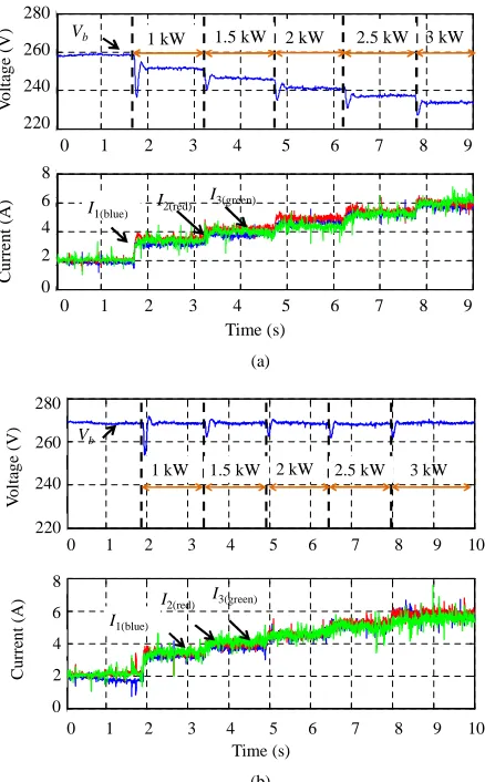
D. Mixed Load
In order to validate the feasibility of the proposed voltage restoration method for the generalized load condition, the
mixed load of CPL and 47 Ω CIL is used below. Droop gain
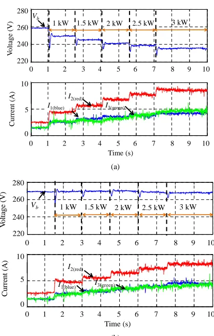
settings are identical with those in Case 1. As shown in Fig. 22(a), the initial voltage is 258 V since the resistive load is always connected to the system and consuming power. With
(a)
[image:10.595.62.261.88.235.2](b)
Fig. 22. Experimental result of mixed load with unequal power sharing using (a) conventional droop control method. (b) proposed compensation method.
TABLEIII
BRANCHCURRENTFORMIXEDLOADS
Load condition
(Unequal sharing)
Branch current before compensation
(I1/I2/I3)
kt= 2 (k1=k3= 8,k2= 4)
Branch current after compensation
(I1/I2/I3)
kt= 2 (k1=k3= 8,k2= 4) CPL (0 kW) + CIL 1.4 A / 2.6 A / 1.4 A 1.5 A / 3 A / 1.5 A CPL (2 kW) + CIL 3.4 A / 6.8 A / 3.4 A 3.3 A / 6.5 A / 3.3 A CPL (3 kW) + CIL 4.3 A / 8.6 A / 4.3 A 4.15 A / 8.3A / 4.15 A
Load condition
(Equal sharing)
Branch current before compensation
(I1/I2/I3)
kt= 2 (k1=k2=k3= 6)
Branch current after compensation
(I1/I2/I3)
kt= 2 (k1=k2=k3= 6)
CPL (0 kW) + CIL 1.84 A each 1.95 A each CPL (2 kW) + CIL 4.48 A each 4.39 A each CPL (3 kW) + CIL 5.85 A each 5.7 A each
the increase of the CPL power, the bus voltage is reduced and
the current-voltage relationship matches the droop
characteristic settings. Fig. 22(b) shows the counterpart experiment result with the proposed voltage compensation method. The unequal sharing results for the mixed load are shown in Fig. 23. The branch currents under different load scenarios are illustrated in Table III. It can be seen that when the resistive load is dominating, the branch current is increased
-4 -3 -2 -1 0 1 2 3 4 5
200 220 240 260 280
-4 -3 -2 -1 0 1 2 3 4 5
0 5 10 15
0 1 2 3 4 5 6 7 8 9 10 0 1 2 3 4 5 6 7 8 9 10
V
o
lt
ag
e
(V
)
C
u
rr
en
t
(A
)
200 220 240 260 280
0 5 10 15
Time (s)
Vb
I2(red)
I1(blue)
I3(green)
-4 -3 -2 -1 0 1 2 3 4 5
200 220 240 260 280
-4 -3 -2 -1 0 1 2 3 4 5
0 5 10
0 1 2 3 4 5 6 7 8 9 10
0 1 2 3 4 5 6 7 8 9 10
V
o
lt
a
g
e
(V
)
C
u
rr
e
n
t
(A
)
200 220 240 260 280
0 5 10
Time (s)
Vb
I2(red) I1(blue)
I3(green)
-4 -3 -2 -1 0 1 2 3 4 5
220 240 260 280
-4 -3 -2 -1 0 1 2 3 4 5
0 5 10
0 1 2 3 4 5 6 7 8 9 10
0 1 2 3 4 5 6 7 8 9 10 Time (s)
Vb
V
o
lt
ag
e
(V
)
220 240 260 280
C
u
rr
en
t
(A
)
0 5 10
I2(red)
I1(blue) I3(green)
1 kW 1.5 kW 2 kW 2.5 kW 3 kW
-4 -3 -2 -1 0 1 2 3 4 5 220
240 260 280
-4 -3 -2 -1 0 1 2 3 4 5 0
5 10
0 1 2 3 4 5 6 7 8 9 10
0 1 2 3 4 5 6 7 8 9 10
Time (s)
Vb
C
u
rr
en
t
(A
)
0 5 10
V
o
lt
ag
e
(V
)
220 240 260 280
I2(red)
I1(blue) I3(green)
[image:10.595.59.261.257.406.2] [image:10.595.298.554.466.649.2]after using the proposed compensation method. However, when the CPL power is increasing and becoming dominant, the branch current is reduced which is in alignment with the analysis in Section IV.
VII. CONCLUSION
In this paper, an enhanced voltage compensation method for the droop-controlled DC EPS has been proposed. The method significantly reduces the voltage regulation and simultaneously establishes the desirable load power sharing among the sources. The proposed approach is easily implemented since no extra controllers and no communication lines are needed, hence the advantages of droop-controlled EPS such as reliability and modularity are retained. The performance of the proposed method under EPS fault scenarios has been demonstrated. It has also shown that the method reduced the total load current and output currents of each source, leading to an improved EPS efficiency due to reduced losses in lines and in sources. Moreover, application of this method increases the overload capacity of EPS generators controlled by power electronic converters. The system stability has also been examined under normal and fault scenarios and it has demonstrated that the proposed method does not deteriorate the system stability.
The paper has also shown the derivation of the criteria of optimal global droop selection for transmission losses minimization in presence of CPL and CIL. In addition, the individual droop settings are investigated to minimize the transmission losses further in parallel source system. The analytical findings of this paper have been validated through laboratory experiments.
APPENDIX
The state space model ofnsources current-mode controlled system
x
A
x
(A-1)whereAis shown as below:
n n k n k n L n R L R n L L n L L n C C n C C b C b C b cpl n n n n n n n n n n res b bV R C P C A 1 1 1 1 1 1 1 1 1 1 1 1 1 1 1 1 1 1 1 1 1 1 * * * 1 1 * 1 * * * 1 * * 1 * 1 2
0
0
0
0
0
0
0
The state space model of n sources current-mode droop controlled system using the proposed voltage compensation method:
x A
x Compen
(A-2)
whereACompenis shown as below:
(a)
(b)
Fig. 23. Experimental result of mixed load with equal power sharing. (a) conventional droop control method. (b) proposed compensation method.
n n k n k t k b V CPL P res R n k n t k b V CPL P res R k n L n R L R n L L n L L n C C n C C b C b C b cpl n n n n n n n n n res b b Compen R V C P C A 1 1 1 1 1 1 1 ) 2 1 ( 1 ) 2 1 ( 1 1 1 1 1 1 1 1 1 1 1 1 1 1 1 1 1 1 * * * 1 1 * * * 1 * * 1 * 1 2
0
0
0
0
0
0
ACKNOWLEDGMENTThe authors would like to thank Dr. Patel Chintanbhai for his kind assistance in setting up the test platform.
REFERENCES
[1] P. Wheeler and S. Bozhko, “The more electric aircraft: technology and challenge,”IEEE Electr. Mag., vol. 2, no. 4, pp. 6–12, Dec. 2014.
-4 -3 -2 -1 0 1 2 3 4
220 240 260 280
-4 -3 -2 -1 0 1 2 3 4
0 2 4 6 8
0 1 2 3 4 5 6 7 8 9
0 1 2 3 4 5 6 7 8 9
Time (s) V o lt ag e (V ) C u rr en t (A ) 220 240 260 280 0 2 4 6 8 Vb I2(red) I1(blue) I3(green)
1 kW 1.5 kW 2 kW 2.5 kW 3 kW
-4 -3 -2 -1 0 1 2 3 4 5
220 240 260 280
-4 -3 -2 -1 0 1 2 3 4 5
0 2 4 6 8
0 1 2 3 4 5 6 7 8 9 10
0 1 2 3 4 5 6 7 8 9 10
Time (s) V o lt ag e (V ) C u rr en t (A ) 220 240 260 280 0 2 4 6 8 Vb I2(red) I1(blue) I3(green)
[image:11.595.308.527.85.438.2][2] X. Roboam, B. Sareni, and A. D. Andrade, “More electricity in the air: toward optimized electrical networks embedded in more-electrical aircraft,”IEEE Ind.Electron.Mag., vol. 6, no. 4, pp. 6–17. Dec. 2012. [3] S. Bifaretti, P. Zanchetta, and E. Lavopa, “Comparison of two
three-phase PLL systems for more electric aircraft converters,”IEEE Trans.
Power Electron., vol. 29, no. 12, pp. 6810–6820, Dec. 2014.
[4] Z. Xu, D. Zhang, F. Wang, and D. Boroyevich, “A unified control for the combined permanent magnet generator and active rectifier system,”
IEEE Trans. Power Electron., vol. 29, no. 10, pp. 5644–5656, Oct.
2014.
[5] W. U. N. Fernando, M. Barnes, and O. Marjanovic, “Direct drive permanent magnet generator fed AC-DC active rectification and control for more-electric aircraft engines,”IET Elect. Power Appl.vol. 5, no. 1, pp. 14–27, Jan. 2011.
[6] C. Wang, X. Li, L. Guo, and Y. Li, “A nonlinear -disturbance-observer-based DC-bus voltage control for a hybrid AC/DC microgrid,”IEEE
Trans. Power Electron., vol. 29, no. 11, pp.6162–6177, Nov. 2014.
[7] T. Dragicevic, J. M. Guerrero, J. C. Vasquez, and D. Skrlec, “Supervisory control of an adaptive-droop regulated DC microgrid with battery management capability”IEEE Trans. Power Electron., vol. 29, no. 2, pp.695–706, Feb. 2014.
[8] S. Anand and B. Fernandes, “Reduced-order model and stability analysis of low-voltage DC microgrid,”IEEE Trans. Ind. Electron., vol. 60, no. 11, pp. 5040–5049, Nov. 2013.
[9] S.-M. Chen, T.-J. Liang, and K.-R. Hu, “Design, analysis, and implementation of solar power optimizer for DC distribution system,”
IEEE Trans. Power Electron., vol. 28, no. 4, pp. 1764–1772, Apr. 2013.
[10] M. Tabari and A. Yazdani, “Stability of a DC distribution system for power system integration of plug-in hybrid electric vehicles,” IEEE
Trans. Smart Grid, vol. 5, no. 5, pp.2564–2573, Sep. 2014.
[11] D. Izquierdo, R. Azcona, F. del Cerro, C. Fernandez, and B. Delicado, “Electrical power distribution system (HV270DC), for application in more electric aircraft,” inProc.25th Annu. IEEE Appl. Power Electron.
Conf. Expo. (APEC), Canada, Feb. 2010, pp. 1300–1305.
[12] S.-C. Shin, H.-J. Lee, Y.-H. Kim, J.-H. Lee, and C.-Y. Won, “Transient response improvement at startup of a three-phase AC/DC converter for a DC distribution system in commercial facilities,”IEEE Trans. Power
Electron., vol. 29, no. 12, pp.6742–6753, Dec. 2014.
[13] H. Zhang, F. Mollet, C. Saudemont, and B. Robyns, “Experimental validation of energy storage system management strategies for a local DC distribution system of more electric aircraft,” IEEE Trans. Ind.
Electron., vol. 57, no. 12, pp.3905–3916, Dec. 2010.
[14] J. M. Guerrero, L. Hang, and J. Uceda, “Control of distributed uninterruptible power supply systems,”IEEE Trans. Ind. Electron., vol. 55, no. 8, pp. 2845–2859, Aug. 2008.
[15] N. Hur and K. Nam, “A robust load-sharing control scheme for parallel connected multisystems,”IEEE Trans. Ind. Electron., vol. 47, no. 4, pp. 871–879, Aug. 2000.
[16] X. Sun, Y.-S. Lee, and D. Xu, “Modeling, analysis, and implementation of parallel multi-inverter system with instantaneous average-current-sharing scheme,”IEEE Trans. Power Electron., vol. 18, no. 3, pp. 844– 856, May 2003.
[17] C-.T. Lee, C-.C. Chu, and P-.T. Cheng, “A new droop control method for the autonomous operation of distributed energy resource interface converters,”IEEE Trans. Power Electron., vol. 28, no. 4, pp. 1980– 1993, Apr. 2013.
[18] A. P. Nobrega Tahim, D .J. Pagano, E. Lenz, and V. Stramosk, “Modeling and stability analysis of islanded DC microgrids under droop control,”IEEE Trans. Power Electron., vol. 30, no. 8, pp. 4597–4607, Aug. 2015.
[19] H. Kakigano, Y. Miura, and T. Ise, “Distribution voltage control for DC microgrids using fuzzy control and gain-scheduling technique,”IEEE
Trans. Power Electron., vol. 28, no. 5, pp. 2246–2258, May 2013.
[20] J. Guerrero, J. C. Vasquez, and L. G. D. Vicuna, “Hierarchical control of droop-controlled AC and DC microgrids—A general approach toward standardization,”IEEE Trans. Ind. Electron., vol. 58, no. 1, pp. 158– 172, Jan. 2011.
[21] T. Dragicevic, J. C. Vasquez, J. M. Guerrero, and D. Skrlec, “Advanced LVDC electrical power architectures and microgrids: A step toward a
new generation of power distribution networks,”IEEE Electr. Mag. vol. 2, no. 1, pp.54–65, Mar. 2014.
[22] X. Lu, J. M. Guerrero, K. Sun, and J. C. Vasquez, “An improved droop control method for DC microgrids based on low bandwidth communication with DC bus voltage restoration and enhanced current sharing accuracy,”IEEE Trans. Power Electron., vol. 29, no. 4, pp. 1800–1812, Apr. 2014.
[23] S. Anand, B. G. Fernandes, and J. M. Guerrero, “Distributed control to ensure proportional load sharing and improve voltage regulation in low voltage DC microgrids,”IEEE Trans. Power Electron., vol. 28, no. 4, pp. 1900–1913, Apr. 2013.
[24] G. Sulligoi, D. Bosich, G. Giadrossi, Z. Lin, M. Cupelli, and A. Monti, “Multiconverter medium voltage DC power systems on ships: constant-power loads instability solution using linearization via state feedback control,”IEEE Trans. Smart Grid, vol. 5, no. 5, pp. 2543–2552, Sep. 2014.
[25] N. Jelani and M. Molinas, “Asymmetrical fault ride through as ancillary service by constant power loads in grid-connected wind farm,”IEEE
Trans. Power Electron., vol. 30, no. 3, pp. 1704–1713, Mar. 2015.
[26] F. Gao, S. Bozhko, G. Asher, and P. Wheeler, “An improved voltage compensation method for droop-controlled system in DC microgrid,” in
Proc.Industrial Electronics Society, 40th Annual Conference of the
IEEE (IECON 2014), Dallas, USA, Nov. 2014, pp.1240–1246.
[27] I. U. Nutkani, P. Wang, P. C. Loh, and F. Blaabjerg, “Cost-based droop scheme for DC microgrid,” inProc.Energy Conversion Congress and
Exposition (ECCE), IEEE, Pittsburgh, USA, Sep. 2014, pp.765–769.
[28] I. U. Nutkani, P. C. Loh, P. Wang, and F. Blaabjerg, “Autonomous droop scheme with reduced generation cost,”IEEE Trans. Ind. Electron., vol. 61, no. 12, pp. 6803–6811, Dec. 2014.
[29] J. Cao, W. Du, H. Wang, and S. Q. Bu, “ Minimization of transmission loss in meshed AC/DC grids with VSC-MTDC networks,”IEEE Trans.
Power Syst., vol. 28, no. 3, pp. 3047–3055, Aug. 2013.
[30] C. Gavriluta, I. Candela, A. Luna, A. Gomez-Exposito, and P. Rodriguez, “Hierarchical control of HV-MTDC systems with droop-based primary and OPF-droop-based secondary,”IEEE Trans.Smart Grid, vol. 6, no. 3, pp.1502–1510, May 2015.
[31] K. Rouzbehi, A. Miranian, A. Luna, and P. Rodriguez, “DC voltage control and power sharing in multiterminal DC grids based on optimal DC power flow and voltage-droop strategy,”IEEE Emerg. Sel. Topics
Power Electron., vol. 2, no. 4, pp. 1171–1180, Dec. 2014.
[32] X. Zhao and K. Li, “Droop setting design for multi-terminal HVDC grids considering voltage deviation impacts,”Elect. Power Syst. Res., vol. 123, pp. 67–75, Feb. 2015.
[33] S. Bozhko, S. Yeoh, F. Gao, and C. Hill, “Aircraft starter-generator system based on permanent-magnet machine fed by active front-end rectifier,” inProc. Industrial Electronics Society, IECON 2014 - 40th
Annual Conference of the IEEE, Dallas, USA, Nov. 2014, pp. 2958–
2964.
[34] F. Gao, Y. Gu, S. Bozhko, G. Asher, and P. Wheeler, “Analysis of droop control methods in DC microgrid,” in Proc Power Electronics and Applications (EPE'14-ECCE Europe), 2014 16th European Conference on, Lappeenranta, Finland, Aug. 2014, pp. 1–9.
[35] Department of Defense of United States of America, “Department of defense interface standard—aircraft electric power characteristics,” Military Std. USA, Mar. 2004.
[36] S. Yeoh, F. Gao, S. Bozhko, and G. Asher, “Control design for PMM-based starter generator system for more electric aircraft,” in Proc. Power Electronics and Applications (EPE'14-ECCE Europe), 16th
European Conference, Lappeenranta, Finland, Aug. 2014, pp. 1–10.
Fei Gao received the M.Sc. degree in Electrical Engineering from Shanghai Jiao Tong University, Shanghai, China, in 2010.
From 2010 to 2012, he has worked in State Grid Corporation of China as an electrical engineer. Currently he is working towards the Ph.D. degree in Power Electronics, Machines and Control Research Group at The University of Nottingham. His current research interests include modelling and control of electrical power system, DC microgrids and power system stability.
Serhiy Bozhko(M’96) received his M.Sc. and Ph.D. degrees in electromechanical systems from the National Technical University of Ukraine, Kyiv City, Ukraine, in 1987 and 1994, respectively.
Since 2000, he has been with the Power Electronics, Machines and Controls Research Group of the University of Nottingham, United Kingdom. Currently he is an Associate Professor in the same research group and leads several EU- and industry funded projects in the area of aircraft electric power systems. His research interests include control and stability issues, power management, as well as advanced modelling and simulations methods.
Greg Asher (SM’02-F’07) obtained a PhD from Bath University, UK in 1979.
He undertook research into superconducting levitators in UCNW Bangor, Wales before being appointed Lecturer in Control in the PEMC Research Group at the University of Nottingham in 1984. He was awarded a Chair in Electrical Drives and Control in 2000, was Head of the School of Electrical and Electronic Engineering from 2004 and Associate Dean of the Engineering Faculty from 2008. Professor Asher is a Fellow of the IEEE and has over 300 publications. His current research interests lie in autonomous power system analysis and control, aircraft electrical power systems, AC drive control and sensorless control.
Prof. Asher has served on the EPE executive council and as Chair for the Power Electronics and Drives Technical Committee for the IEEE Industrial Electronics Society.
Pat Wheeler (SM’11) received his BEng [Hons] degree in 1990 from the University of Bristol, UK. He received his PhD degree in Electrical Engineering for his work on Matrix Converters from the University of Bristol, UK in 1994.