Elsevier Editorial System(tm) for Applied Thermal Engineering
Manuscript Draft
Manuscript Number: ATE-2013-5383R1
Title: Computer modelling and experimental investigation of building integrated sub-wet bulb temperature evaporative cooling system Article Type: Research Paper
Keywords: Evaporative cooling, sub-wet bulb temperature, heat and mass transfer, wet media, dew point
Corresponding Author: Dr. Rabah Boukhanouf, PhD
Corresponding Author's Institution: University of Nottingham First Author: Rabah Boukhanouf, PhD
Order of Authors: Rabah Boukhanouf, PhD; Abdulrahman Alharbi, BEng, MSc; Hatem G Ibrahim, PhD; Omar Amer, MSc; Mark Worall, PhD
Abstract: The paper presents computer modelling and laboratory experiment results of a sub-wet bulb temperature indirect evaporative cooling system for space cooling in buildings. The prototype employs hollow porous
ceramic water containers as wet media material for water evaporation. The cooled air is delivered without increasing its moisture content. The performance of the cooler was evaluated using a computer model, and the results of which were validated experimentally. The cooling capacity and effectiveness of the cooler were evaluated at inlet air dry bulb
temperature of 30 and 35o C and relative humidity ranging from 35% to 50%. It was found that the cooler can supply air for space cooling at sub-wet bulb temperature conditions; achieve measured cooling capacity approaching 225 W/m2 of exposed ceramic material wet surface area and wet bulb effectiveness higher than unity. The high thermal performance of the constructed evaporative cooler indicates the system could be a potential substitute to conventional mechanical air-conditioning systems in
Highlights
Computer modelling of a sub-wet bulb temperature evaporative cooler. Experimental validation of the computer model.
High measured cooling capacity of 225 W/m2 of wet surface area. High wet bulb effectiveness of 1.02.
Computer modelling and experimental investigation of building integrated sub-wet bulb temperature
evaporative cooling system
Rabah Boukhanouf*, Abdulrahman Alharbi*, Hatem G Ibrahim#, Omar Amer* and Mark Worall*
*Nottingham University, Faculty of Engineering, Nottingham, NG7 2RD, UK e-mail: [email protected]
#
Qatar University, Department of Architecture and Urban Planning, Doha, Qatar e-mail: [email protected]
Abstract
The paper presents computer modelling and laboratory experiment results of a sub-wet bulb temperature indirect evaporative cooling system for space cooling in buildings. The prototype employs hollow porous ceramic water containers as wet media material for water evaporation. The cooled air is delivered without increasing its moisture content. The performance of the cooler was evaluated using a computer model, and the results of which were validated experimentally. The cooling capacity and effectiveness of the cooler were evaluated at inlet air dry bulb temperature of 30 and 35o C and relative humidity ranging from 35% to 50%. It was found that the cooler can supply air for space cooling at sub-wet bulb temperature conditions; achieve measured cooling capacity approaching 225 W/m2 of exposed ceramic material wet surface area and wet bulb effectiveness higher than unity. The high thermal performance of the constructed evaporative cooler indicates the system could be a potential substitute to conventional mechanical air-conditioning systems in buildings in many parts of the world where hot and dry climatic conditions prevail.
Keywords
Evaporative cooling, sub-wet bulb temperature, heat and mass transfer, wet media, dew point.
1. Introduction
Energy consumption in buildings stands at between 30–40% of the total primary energy use globally [1, 2]. A major part of this is used to provide comfort conditions for occupants. For example, in regions with cold and temperate climates such as northern Europe, energy for space heating and hot water accounts for over 60% of the total energy use in buildings, whereas in hot climate regions, a similar proportion of energy consumption is required for space air cooling in buildings. The growing demand for air-conditioning systems in the world is Manuscript
mainly driven by the increase in living standards, affordability, population growth and cheap energy in some parts of Middle East. This has led to peak electricity loads increasing sharply in many countries with severe strains on electricity grids, putting pressure on governments to respond with short term measures of building new fossil-fuelled power plants and extending the grid infrastructure, which in turn is costly and impacts negatively on the environment.
Currently, the market for air-conditioning systems is dominated by mechanical vapour compression systems, which are energy-intensive systems and suffer from low performance in hot climates where they are often required. In hot and dry climates such as desert climates, application of low carbon cooling technologies such as evaporative cooling can offer a viable solution for space cooling in buildings. The current focus for many researchers includes methods of integrating evaporative cooling into contemporary architecture and the development of novel wet media materials for efficient evaporation of water. Duan et al [3] conducted an extensive review of indirect evaporative cooling technology and pointed out the continuous development of the technology. The authors concluded that indirect evaporative cooling systems have the potential to be a viable alternative to conventional mechanical vapour compression refrigeration systems in air conditioning in buildings.
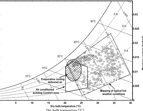
The use of evaporative cooling for thermal comfort in buildings was practiced by ancient Egyptians and the Romans for hundreds of years by placing a wet mat over a door or window frame in the summer time through which prevailing winds force air into the building living space [4]. Today, this method of space cooling has been refined and adopted for modern buildings in hot and arid areas such as Middle East, South western part of the United States and the Indian subcontinent [5]. For example, in Saudi Arabia, there are over 48,000 rooftop-mounted direct evaporative air coolers installed in tents accommodation, railway stations and public spaces [6]. In such climates, evaporative cooling can be an effective solution in achieving space comfort in buildings for most times of the year. Fig. 1 shows that evaporative cooling systems, when operating at
optimum conditions, can meet the comfort requirement in buildings by bringing depressing the ambient air dry bulb temperature and humidity to within the required building comfort zone for air conditioned building [7].
1.1Arrangements of evaporative cooling technology
content. Modern direct evaporative cooling systems employ sophisticated wet pad materials through which forced air is drawn in by a fan for direct contact between the airstream and water [8].
In contrast, in an indirect evaporative cooler, the supply air is cooled without increasing its moisture content. This is accomplished by using a heat exchanger to separate the dry and hot inlet airflow from the cool and wet outlet airflow in the wet channel [3]. The temperature gradient necessary for heat transfer between the two airflows is influenced by the wet bulb temperature of the airflow in the wet channel where direct evaporation takes place. The cool air in the dry channel is then supplied without increasing its moisture content. However, in such systems, the supply air is at best cooled to within 2 to 3 oC of the wet bulb temperature. This
constitutes a severe thermodynamic limitation, and a disadvantage compared to vapour mechanical air-conditioning systems.
An improvement to the cooling process of indirect evaporative cooling systems has been the focus of many leading researchers with the aim of increasing thermal effectiveness and supplying air temperatures below the ambient air wet bulb temperature. The pioneer work of Maisotsenko led to the development of the M-cycle which for the first time sub-wet bulb temperatures can be achieved by an evaporative cooling process. The M-cycle is a combination of a cross-flow, multi-perforated flat-plate heat exchanger and evaporative cooling, in which; the supply air is cooled in the dry channel at constant moisture content part of which is diverted to wet channel to perform the evaporation process [9]. Thus, the wet channel air temperature is decreased below the bulb temperature, and the lower boundary limit can be extended to the dew-point temperature of the incoming air. This type of evaporative cooling system is also referred to as dew point or sub-wet bulb temperature indirect evaporative cooling. Recently, many arrangements of these systems have been successfully
demonstrated to achieve high thermal performance with wet-bulb and dew-point effectiveness ranging from 110 to 122% and 55% to 85% respectively [9].
Hsu et al. [10] carried out a theoretical and experimental study on two configurations of closed-loop wet surface heat exchangers that achieved sub-wet bulb temperature cooling conditions through a counterflow and cross flow air stream arrangement. Boxem et al. [11] presented a model for a 400 m3/h compact counterflow indirect evaporative cooler with finned heat exchanger and showed that for dry bulb temperatures greater than 24 oC, the predicted model accuracy is 10% of the measured performance. Zhao et al. [12] presented a
wet bulb effectiveness was also high and ranged between 92 to 114%. Hasan [14] also presented a theoretical model of four different configurations of indirect and sub-wet bulb temperature coolers where the supply and working air arranged in separate ducts and : a two-stage counter flow cooler, a two-stage parallel flow cooler, a single-stage counter flow regenerative cooler and a combined parallel-regenerative cooler. The author concluded that the ultimate temperature to which the air could be cooled to be the dew point of ambient air. Recent work by Lee [15] using a counter flow regenerative evaporative cooler has also shown that sub-wet bulb temperatures are achievable. The authors built and tested a prototype unit using finned aluminium plates for heat transfer augmentation. The experiment results show that for air inlet of 32o C dry bulb temperature and 50% relative humidity, the supply air was cooled to 22o C, which is below the inlet air wet bulb temperature of 23.2. Miyazaki et al. [16] conducted computer simulation of a solar chimney driven dew-point evaporative cooling system integrated into the building ceiling. The results showed that the system could achieve a cooling capacity of 40–50 W/m2 and capable of reducing the maximum cooling load of an office building by more than 10%.
1.2
Selection of wet media materials
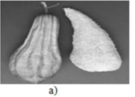
The wet media used in evaporative coolers is a core component of the system. It is usually made of a porous material with a large microscopic surface area for enhancing mass transfer between water and air. The selection of the wet media materials depends on the application, availability, cost, safety, and environmental impact [17]. Zhao et al. [18] investigated various types of porous materials such as metal and plastic foams, zeolite and carbon fibres to be used as wet media for heat and mass transfer in evaporative cooling systems. Musa [19] also investigated the use of more common Aspen materials in the form of pads for the indirect evaporative cooling systems. Application of indigenously grown organic materials such as Luffa sponge and palm dates' fibres as unstructured wet cooling pads were also attempted, as shown in Fig. 2 [20].
Further investigations were conducted using building construction materials such as fired clay and porous ceramics as wet media in evaporative cooling systems. These mainly were intended to be a fully integrated functional building element. Compared to traditional fired-clay materials, porous ceramics combine various chemical elements and binders such as alumina (Al2O3), silicon oxides (SiO2), and nitrides (Si3N4). In addition,
In this paper, investigation of adopting ceramic materials as wet media for building integrated sub-wet bulb temperature evaporative cooling system was carried out. A computer model and a small-scale laboratory experiment were conducted to evaluate the thermal performance of viability of the cooling system.
2 Description of the sub-wet bulb temperature evaporative cooler
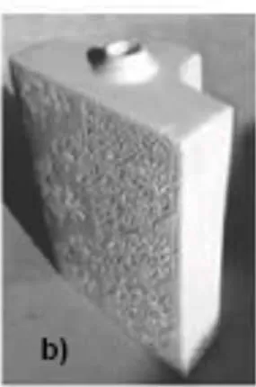
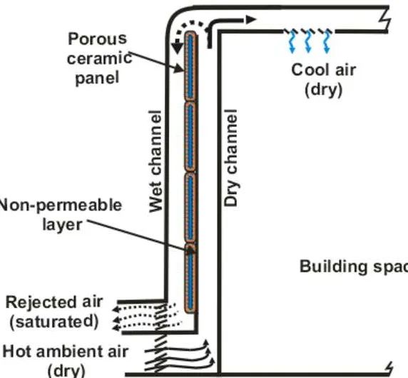
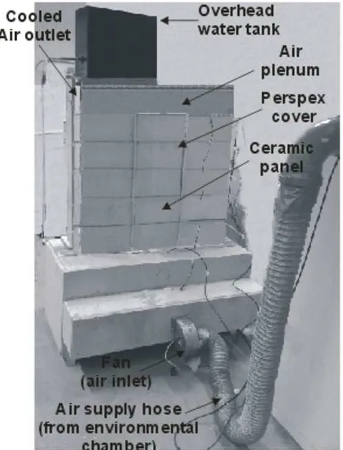
A porous ceramic panel in the form of hollow flat blocks was used as wet media in a sub-wet bulb temperature evaporative cooler. The porous ceramic panels were placed in a rigid frame to form a wall structure which was then sandwiched between two Perspex panels to form two narrow channels to the front and back of the
structure. The front surface of the porous ceramic panels was sealed with a thin water proof membrane while the back surface was left an altered. When filled with water, the front surface of the ceramic panels remains dry to form part of the dry channel while water sips through the micro-pores of the panels on the back surface to wet its surface and form the wet channel. The principle of cooling air to temperature below that of the wet bulb temperature is then achieved by recirculating part of the cool air in the dry channel through the wet channel as shown by the arrangement of Fig. 4. The direct evaporation of water from the surface of the ceramic panels in the wet channel cools the panel and its water content creating a temperature gradient across the water-proof membrane. This allows the airflow in the dry channel to be cooled without increasing its moisture content while the air in the wet channel is rejected at saturation condition.
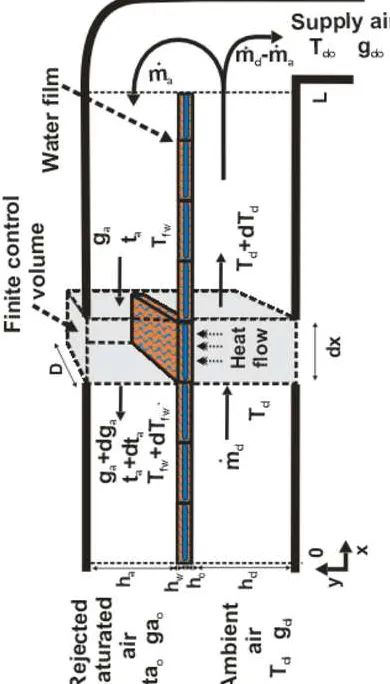
3 Mathematical model
A one-dimensional mathematical model based on solving energy and mass conservation governing equations was developed. In the model, the dry and wet channel and water film on the ceramic material surface were subdivided along the air flow path into small finite volumes in each of which the air properties, heat and mass transfer coefficients were assumed to be constant. A one-dimensional representation of the finite control volumes along the airflow channels is illustrated in Fig. 5.
3.1 Energy conservation equation for the dry channel
lowest temperature being that of the water film at the back of the porous ceramic panel. This can be expressed as follows [24]:
) ( d fw d d pa d T T U dx dT D c m (1)
The overall heat transfer coefficient, Ud is evaluated between the dry channel and the water film on the porous
ceramic surface in the wet channel and is given as follows [14]:
w w csw c d d h h U 1
1 (2)
The thickness of the water-proof membrane and water film layer of the dry and wet side of the ceramic panel respectively are very small (in the order of 0.01 mm) leading to their respective thermal resistance being neglected in Eq (2). On the other hand, the thermal conductivity of water saturated porous ceramic panel wall, λcsw, was computed from the follows expression [25]:
) )( 1 ( ) )( 1 ( [ c w c w c w c w w
csw
(3)
The convective heat transfer properties of the air flow in the narrow dry channel formed between two plates in Fig. 5 is evaluated from Nusselt number, as following [26]:
(4)
The convective heat transfer coefficient, d, is then obtained from:
(5)
3.2 Energy conservation in the wet channel
The heat transfer process in the wet channel involves the exchange of sensible heat of air with latent heat of the water evaporating from the surface of the porous ceramic panel. The heat transfer process within a finite control volume along the wet channel as shown in Fig. 5 can be expressed as follows [24]:
fg a fw a a fw a a pa a h g g t T dx dt D c m ) ( ) ( (6)
Assuming the evaporation rate of water vapour in the wet channel is low compared to the air mass flow rate, the convective heat transfer coefficients, αa, between the water film and the bulk airflow was evaluated using
Eq. (4) and (5). Similarly, the convective mass transfer coefficient, σa, between the water film and the bulk air
(7) where Schmidt number,
and coefficient, Dim is the water vapour diffusion coefficient in the air flow. The convective mass transfer coefficient, σa in Equation (6) is given by:
(8)
3.3 Mass conservation in the wet channel
The Mass conservation equation expresses the amount of water vapour transfer from the ceramic panel surface into the bulk airflow in the wet channel which appears as an increase in moisture content of air in the direction of the airflow. The water vapour mass convection rate is driven by the moisture content gradient between the saturated water film and the bulk air in the wet channel. This can be expressed as:
) ( fw a
a a a g g dx dg D
m (9)
The bulk mass flow rate of air in the wet channel is assumed to be unaffected by the vapour mass transfer rate from the ceramic wet surface (low diffusional vapour flow rate). This is valid if the mass transfer driving force coefficient, Bm, given by the following expression is less than 0.2 [25]:
fw a fw m g g g B
1 (10)
3.4 Overall energy balance
The overall energy balance across the two airflow channels and the saturated ceramic panel must be satisfied across an elemental control volume. This is accomplished by considering the rate of energy accumulation and transfer in the water film at the wet surface of the ceramic panel, energy transfer rate from airflow in the dry channel, water evaporation rate and energy transfer by convection in the wet channel. This can be written for each control volume as follows:
) (
) (
)
( d fw a fw a fg a fw a d fw pfw fw t T h g g T T U dx dT D c m (11)
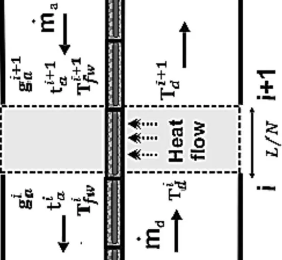
3.5 Computer model discretization and design parameters
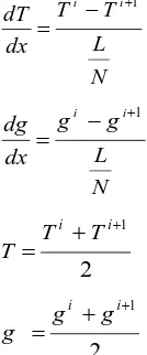
It was assumed that the airflow properties in each control volume are constant, and the first derivative of temperature and moisture content is evaluated at the centre of each element as follows:
N L T T
dx
dT i i1 (12)
N L g g
dx
dg i i1 (13)
2 1 i i T T
T (14)
2 1 i i g g
g (15)
Equation 12 to 15 were substituted into governing heat and mass transfer equations (Eq. 1, 6, 9 and 11) and a set of discrete equations of air flow temperature, moisture content and water film temperature was derived.
The discretised mathematical model was completed by a set of initial and boundaries conditions. The initial conditions involve particularly the prevailing ambient air conditions at the system’s inlet, which are expressed as [27]: di t fw t a t
d t T T
T 0 0 0 (16)
di t a t
d g g
g 0 0 (17)
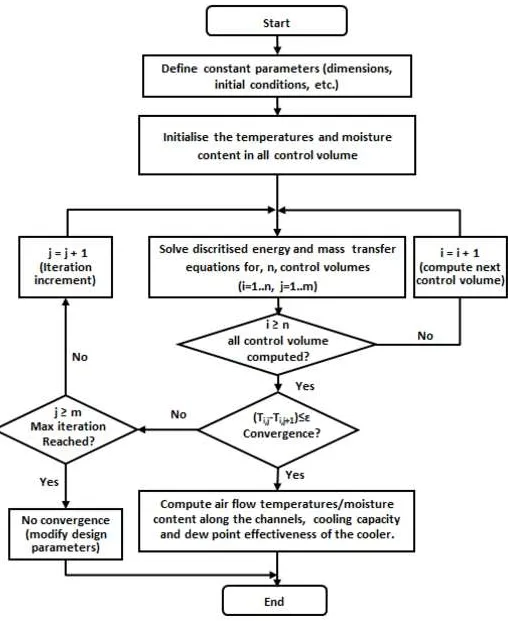
It was also assumed that no heat is transferred through the external boundaries of the system. The computed numerical solution was marched iteratively along the dry and wet channels coordinate until convergence is satisfied with a temperature difference between two consecutive iterations of less than ε (Ti,j+1-Ti,j<0.01
o
[image:10.612.73.140.93.254.2]C). Fig. 7 shows a simplified algorithm of the computer model.
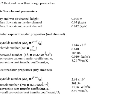
4 The experimental test rig
louvered air grill. As pointed out previously, the air flow in both channels was assumed to occur over a large flat annular channel. The main design parameters of the air flow in the dry and wet channels including Reynold number, heat and mass transfer coefficients are summarised in Table 2.
The inlet fan draws in air to the rig from an enclosed environmental chamber in which the air temperature and moisture content were finely controlled. The rig was fully instrumented for measuring air temperatures, moisture content and air flow rate at various positions along the air channels.
3. Results and discussion
The thermal performance of the sub-wet bulb temperature cooler was evaluated for air inlet temperature of 35
o
C (wet bulb temperature of 22.9 oC) and relative humidity of 35% to simulate typical hot and dry weather conditions in many parts of the world. The air in the dry channel was supplied from a controlled environment at mass flow rate of 0.03 kg/s while the air mass flow rate in the wet channel was set to 0.012 kg/s. The steady state measured temperatures at the inlet and outlet of the dry channel and outlet of the wet channel are shown in Fig. 8. The measurement shows the airflow temperature dropped by about 12.4 oC along the dry channel, resulting in supply air temperature of 22.6 oC (lower than the inlet air wet bulb temperature).
The computer model and experimental results of steady state airflow temperature profiles along the dry and wet channels and on the porous ceramic surface are shown in Fig. 9(a). It is shown that both temperature variation trends and measured values are in good agreement with simulation results. The airflow in the dry is cooled through sensible heat transfer to the cool ceramic panel, which temperature decreases along the dry channel length. Simultaneously, the air in the wet channel interchanges its sensible heat for latent heat of water evaporating from the surface of the ceramic panel, increasing its temperature along the wet channel. The measured temperature of air at the dry channel outlet was 22.6 oC compared to computed value of 22.0 oC, a difference of only 2.65%. The computed values of airflow temperature along the wet channel increased from 22.0 oC to 24.31 oC, whereas, the measured temperature increased to only 25 oC. The discrepancy between the measured and computed temperature value in the wet channel is about 9.6 %. This is mainly attributed to difficulties in obtaining a uniform water film distribution on the surface of the ceramic panel, which temperature increased from 21.34 to 25.93 oC.
The evolution of air moisture content in the wet channel is shown in Fig. 9(b). The moisture content increases from 12.6 kg/kgd at the inlet of the wet channel to 16.8 kg/kgd indicating that the air exits the wet channel fully
saturated. The measured moisture content at the inlet and outlet were in good agreement with the simulation results.
channel exits at temperature, Tdo, below the wet bulb temperature of the inlet air, Twb. Theoretically, the air at
the outlet of the dry channel could be cooled to its corresponding dew point value, Tdp of approximately 18 o
C.
The performance of the ceramic porous cooler was further examined to assess the effect of relative humidity and inlet air temperature variation. The analysis was carried out for two dry bulb temperature settings of 30 and 35 oC and relative humidity ranging from 35 to 50 % while the airflow rate in the dry and wet channel remains constant at 0.03 and 0.012 kg/s respectively. The computer simulation and measured cooling capacity per unit of surface area of the wet ceramic media is shown in Fig. 11. It can be seen that the specific cooling capacity is strongly influenced by the dry channel inlet air relative humidity and dry bulb temperature. For a given dry bulb temperature, the cooling capacity of the cooler deteriorates quickly as relative humidity increases. However, for a given relative humidity, the cooling capacity increases for higher dry bulb temperature of inlet air. The difference between measured and computer modelling cooling capacity of the cooler varied between 3 and 7.8 % over the range of relative humidities and dry bulb temperatures of the inlet air.
Finally, the performance of the evaporative cooler was also evaluated by calculating the wet bulb and dew point effectiveness. The wet bulb effectiveness is the ratio of the difference between inlet and outlet airflow dry bulb temperature to the difference between the inlet airflow dry bulb temperature and its wet bulb temperature. The mathematic expression for wet bulb effectiveness is given by [28].
wb=wi di do di T T T T (18)
For air inlet condition of 35 oC dry bulb temperature and 35% relative humidity, the wet bulb temperature is 22.9 oC, resulting in a computed and measured web bulb effectiveness of 1.074 and 1.024 respectively with an error of 4.65%. This shows that the wet bulb temperature effectiveness is greater than unity as the airflow temperature at the outlet of the dry channel is cooled below its wet bulb temperature.
The dew point effectiveness, on the other hand, is the ratio of the difference between the inlet and outlet airflow dry bulb temperature to the difference between the inlet airflow dry bulb temperature and its dew point temperature. The mathematic expression for the dew point effectiveness is given by [28]:
dp=dp di do di T T T T (19)
4. Conclusion
The paper presents a computer model and experimental results of a sub-wet bulb temperature evaporative cooler using porous ceramic materials for thermal comfort application in buildings. A formulation of the computer model, construction and testing of a prototype cooler was conducted. It was shown that the evaporative cooler has the potential to achieve required thermal comfort in buildings in regions of the world with hot and dry climates. The major findings of this work relate particularly to the following:
Development and validation of a computer model with good agreement between measured and computed results.
Use of inert porous ceramic materials has the advantage of integration with building elements (e.g., wall, ceiling and floor).
A maximum measured cooling capacity of 225 W/m2 of the porous ceramic wet surface area was attained under favourable conditions. Though this also depends on the ceramic material properties and available surface area.
A wet bulb effectiveness of the system of 1.024 was achieved.
The influence of ambient air properties was investigated and it was shown that the thermal performance depends strongly on the relative humidity of inlet air.
Finally, the use of porous ceramic materials for cooling lends itself well to integration with building elements. With the advantage of structural stability and manufacturing easiness, building integrated ceramic materials evaporative cooling could be a substitute for traditional vapour compression air conditioning systems in regions with hot and dry climatic conditions.
5. Acknowledgement
6. References
[1] Dodoo, A., L. Gustavsson, and R. Sathre, Building energy-efficiency standards in a life cycle primary energy perspective. Energy and Buildings, 2011. 43(7): p. 1589-1597.
[2] Pérez-Lombard, L., Ortiz, J., Juan F. Coronel, J F. and Maestre, I.R., A review of HVAC systems requirements in building energy regulations. Energy and Buildings, 2011. 43(2-3): p. 255-268. [3] Duan, Z., Zhan, C, Zhang, X., Mustafa, M., Zhao, X., Alimohammadisagvand, B., Hasan, A., Indirect
evaporative cooling: Past, present and future potentials. Renewable and Sustainable Energy Reviews, 2012. 16(9): p. 6823-6850.
[4] Vissers, D.R., Study on Building integrated evaporative cooling of glass-covered spaces, in Building Physics and Systems 2011, Eindhoven University of Technology.
[5] Bom, G. J., Dijkstra, E.R.F., Tummers, M., Evaporative Air-Conditioning Applications for Environmentally, 1999, The Word Bank Washington, D.C.
[6] Alharbi, A., Boukhanouf, R., Habeebullah, T. and Ibrahim, H., Thermal Performance and
Environmental Assessment ofof Evaporative Cooling Systems: Case of Mina Valley, Saudi Arabia. International Journal of Civil, Architectural, Structural and Construction Engineering, 2014 8(5) p 539-5443.
[7] California energy commision, Residential evaporative cooling. Available from:
http://www.consumerenergycenter.org/residential/heating_cooling/evaporative.html. [cited 10/12/2015].
[8] Jones, W.P, Air Conditioning Engineering, 5th Edition, Butterworth Heinemann , 2001.
[9] Maisotsenko V, G.L., Heaton T.L. Gillan Ad., Method and plate appartus for dew point evaporative cooler , 2003: United State patent No. US 6581402 B2.
[10] Hsu, S.T., Z. Lavan, and W.M. Worek, Optimization of wet-surface heat exchangers. Energy, 1989. 14(11): p. 757-770.
[11] Boxem, G.S.B.and Zeiler,W., Performance model for small scale indirect evaporative cooler. in Proceedings of Clima WellBeing Indoors, REHVA World Congress. 2007. Finland.
[12] Zhao, X., Li, J.M., and Riffat, S.B., Numerical study of a novel counter-flow heat and mass exchanger for dew point evaporative cooling. Applied Thermal Engineering, 2008. 28(14-15): p. 1942-1951. [13] Riangvilaikul, B. and Kumar,S., An experimental study of a novel dew point evaporative cooling
system. Energy and Buildings, 2010. 42(5): p. 637-644.
[15] Lee, J. and Lee D.Y, Experimental study of a counter flow regenerative evaporative cooler with finned channels. International Journal of Heat and Mass Transfer, 2013. 65(0): p. 173-179.
[16] Miyazakia, T., Akisawaa, A., and Nikaib, I., The cooling performance of a building integrated evaporative cooling system driven by solar energy. Energy and Buildings, 2011. 43: 2211–2218. [17] Wanphen, S. and Nagano, K., Experimental study of the performance of porous materials to moderate
the roof surface temperature by its evaporative cooling effect. Building and Environment, 2009. 44(2): p. 338-351.
[18] Zhao, X., Liu , S., and Riffat, S.B., Comparative study of heat and mass exchanging materials for indirect evaporative cooling systems. Building and Environment, 2008. 43(11): p. 1902-1911. [19] Musa, M., Novel Evaporative Cooling Systems for Building application, PhD Thesis, in Architecture
and Built Environment, May 2008, The University of Nottingham: Nottingham. p. 61-70, 234. [20] Al-Sulaiman, F., Evaluation of the performance of local fibers in evaporative cooling. Energy
Conversion and Management, 2002(43): p. 2267-2273.
[21] Schiano-Phan, R. The use of porous ceramic for passsive evapoartaive cooling in buildings. 2009; Available from: http://www.phdc.eu/uploads/media/PHDC_Cooling_with_porous_ceramic_01-06-09.pdf.
[22] Ibrahim, E., Shao, L., and Riffat, S.B., Performance of porous ceramic evaporators for building cooling application. Energy and Buildings, 2003. 35(9): p. 941-949.
[23] Riffat, S.B. and Zhu, J., Mathematical model of indirect evaporative cooler using porous ceramic and heat pipe. Applied Thermal Engineering, 2004. 24(4): p. 457-470.
[24] Halasz, B., A general mathematical model of evaporative cooling devices. Elsevier, Paris, 1998: p. 245-255.
[25] Riangvilaikul, B. and S. Kumar, Numerical study of a novel dew point evaporative cooling system. Energy and Buildings, 2010. 42(11): p. 2241-2250.
[26] Lienhard IV, J. H. and Lienhard V, J. H., A heat transfer text book, , 4th edition, Phlogiston Press, Cambridge Massachusetts, 2012.
[27] Moshari, S. and Heidarinejad, G., Numerical study of regenerative evaporative coolers for sub-wet bulb cooling with cross- and counter-flow configuration. Applied Thermal Engineering, 2015. 89: p. 669–683.
Nomenclature
Specific heat capacity of air (J/kg K)
Specific heat capacity of water (J/kg K)
Depth of airflow channel (m)
Water vapour diffusion coefficient in the wet channel (m2/s)
Control volume step length (m)
Moisture content of air (kg/kgd)
Moisture content of air in the wet channel (kg/kgd)
Outlet air moisture content of wet channel (kg/kgd)
Outlet air moisture content of dry channel (kg/kgd)
Thickness of ceramic container (m)
Moisture content of air at saturation (kg/kgd)
Latent heat of vaporisation of water (J/kg)
Thickness of water layer in the ceramic container (m)
Height of dry channel (m)
Height of wet channel (m)
Wall thickness of ceramic panel (m)
Air thermal conductivity (W/m K)
Length of airflow channel (m)
Air mass flow rate in the wet channel (kg/s)
Air mass flow rate in the dry channel (kg/s)
Water mass flow rate in the wet channel (kg/s)
Nusselt number (-)
Prandtl number (-)
Reynold number (-)
Sherwood number (-)
Schmidt number (-)
Air dry bulb temperature (o C)
Air dry bulb temperature in the wet channel (o C)
Wet channel outlet air dry bulb temperature (o C)
Air dry bulb temperature in the dry channel (o C)
Dry channel inlet air dry bulb temperature (o C)
Dry channel outlet air dry bulb temperature (o C)
Inlet air dew point temperature in the dry channel (o C)
Air temperature of the water film on the surface of the ceramic panel (o C)
Inlet air wet bulb temperature in the dry channel (o C)
Overall heat transfer coefficient (W/m2K)
Air flow direction coordinate (m)
Greek symbols
Convective heat transfer coefficient in the dry channel (W/m2K)
Convective heat transfer coefficient in the wet channel (W/m2K)
Dew point effectiveness (-)
Thermal conductivity of dry ceramic material (W/mK)
Thermal conductivity of water saturated ceramic panel (W/mK)
Thermal conductivity of water layer in the hollow ceramic panel (W/mK)
Air dynamic viscosity (kg/m s)
Porosity of the dry ceramic material (-)Density of air (kg/m3)
Table 1 The porous ceramic container design parameters
Design parameters
Dimension
Porous ceramic panel height Porous ceramic panel width Porous ceramic panel depth Wall thickness
Properties
materials composition Porosity
Density
Thermal conductivity
120 mm 210 mm 45 mm 4 mm
Al2O3, SiO2, Si3N4
Table 2 Heat and mass flow design parameters
Airflow channel parameters
Dry and wet air channel height Mass flow rate in the dry channel Mass flow rate in the wet channel
Water vapour transfer properties (wet channel)
Reynolds number ( ) Schmidt number (
)
Sherwood number ) Convective vapour transfer coefficient, σa
Convective heat transfer coefficient, αa
Heat transfer properties (dry channel)
Reynolds number ( ) Nusselt number ) Convective heat transfer coefficient, αd
Overall convective heat transfer coefficient, Ud
0.005 m 0.03 (kg/s) 0.012 (kg/s)
1.046 x 10⁵ 0.648 185.86 0.0104 kg/m2s 8.26 W/m2K
0 5 10 15 20 25 30 35 40 0 0.005 0.01 0.015 0.02 0.025 0.03
Dry bulb temperature [°C]
M o is tu re c o n te n t (k g /k g d ) 10°C 15°C 20°C 25°C 30°C 0.2 0.4 0.6 0.8 0 .8 0.8 25 0.8 75 0.9 0.9 25
building Comfort zone weather conditions
Evaporative cooling
Dry bulb temperature (°C)
Mapping of typical hot Air conditioned
[image:22.595.74.553.83.457.2]delivered air
Figure 2
Figure 3
Figure 4
Figure 5
Figure 6
Figure 7
Figure 8
Figure 9
Figure 10a
Figure 10b
Figure 11
Figure 12