PERFORMANCE EVALUATION OF HEAT PUMP USING SIMULATION TECHNIQUES FOR
REPLACING ELECTRIC WATER HEATING SYSTEM TO ACHIEVE ENERGY CONSERVATION
AND IMPROVE IEQ IN AN PROCESS INDUSTRY
*Jadhav, G. B., Nalawade
Department of Technology, Shivaji University, Kolhapur, Maharashtra, India
ARTICLE INFO ABSTRACT
In a process industry heat pump can be used for water heating application for an energy conservation application. The
electrical heaters
process industry. The paper also shows the results of indoor environmental
heat pump around its surroundings. The compressor consumption analysis has done for electrical heater and heat pump also simulated results for compressor is shows in this paper. Electricity consumption has been reduced by designing
Copyright © 2015 Jadhav et al. This is an open access article distributed under the Creative Commons Att distribution, and reproduction in any medium, provided the original work is properly cited.
INTRODUCTION
Heat pumps use electricity to transfer heat from one place to another to provide heating or cooling. The basic components of heat pumps include a compressor, condenser, expansion valve, and evaporator. The importance of energy conservation has been highlighted by in EC ACT- 2001 by Govt. of India. The total potential of energy conservation by Energy Management and Energy Efficiency Improvement Program is estimated to 25000 MW. There is a potential of saving 25
various designated agencies of MSME. In manufacturing and process industries, the process designs are based on the type of machine installed at the time of machine erection and commissioning. However, with the time and t
development they become obsolete and the efficiency of the machine and process goes down. Under the circumstances to improve the efficiency of the system, it is necessary to integrate the new technologies under Energy Efficiency Improvement Program.
*Corresponding author: Jadhav, G. B.
Department of Technology, Shivaji University, Kolhapur, Maharashtra, India.
ISSN: 0975-833X
Article History:
Received 24th May, 2015
Received in revised form 26th June, 2015 Accepted 16th July, 2015
Published online 21st August,2015
Key words:
Heat pump, Simulation, IEQ, Energy conservation, Electric heater.
Citation:Jadhav G. B., Nalawade S. N., Shinde
techniques for replacing electric water heating system to achieve energy conservation and improve IEQ in an process industry,
Journal of Current Research, 7, (8), 19010-19017
RESEARCH ARTICLE
PERFORMANCE EVALUATION OF HEAT PUMP USING SIMULATION TECHNIQUES FOR
REPLACING ELECTRIC WATER HEATING SYSTEM TO ACHIEVE ENERGY CONSERVATION
AND IMPROVE IEQ IN AN PROCESS INDUSTRY
, Nalawade, S. N., Shinde N. N.
and Doshi, S. A.
Department of Technology, Shivaji University, Kolhapur, Maharashtra, India
ABSTRACT
In a process industry heat pump can be used for water heating application for an energy conservation application. The theoretical design for heat pump is designed from the point of view replacing electrical heaters. This paper presents simulation results of designed heat pump for water heating in a process industry. The paper also shows the results of indoor environmental
heat pump around its surroundings. The compressor consumption analysis has done for electrical heater and heat pump also simulated results for compressor is shows in this paper. Electricity consumption has been reduced by designing and simulating heat pump process.
is an open access article distributed under the Creative Commons Attribution License, which distribution, and reproduction in any medium, provided the original work is properly cited.
Heat pumps use electricity to transfer heat from one place to another to provide heating or cooling. The basic components of heat pumps include a compressor, condenser, expansion valve, evaporator. The importance of energy conservation has 2001 by Govt. of India. The total potential of energy conservation by Energy Management and Energy Efficiency Improvement Program is estimated to ntial of saving 25-30% of energy in various designated agencies of MSME. In manufacturing and process industries, the process designs are based on the type of machine installed at the time of machine erection and commissioning. However, with the time and technological development they become obsolete and the efficiency of the machine and process goes down. Under the circumstances to improve the efficiency of the system, it is necessary to integrate the new technologies under Energy Efficiency Improvement
Department of Technology, Shivaji University, Kolhapur,
I. Design of Heat pump technology
1.Heat Capacity
Q =m*Cp*Δt
2.Theoretical COP of the system
COP (th) = refrigeration effect/ compressor work
Refrigeration effect = h1 - h6 Compressor work = h2 – h1
3. Refrigerant mass flow rate
Heat added to cold water = Heat rejected from condenser
Q = mr * Δ hr
4. Compressor work and selection
WC = mr *(h2-h1
Available online at http://www.journalcra.com
International Journal of Current Research
Vol. 7, Issue, 08, pp.19010-19017, August, 2015
INTERNATIONAL
Shinde N. N.and S. A. Doshi, 2015. “Performance evaluation of heat pump using simulation techniques for replacing electric water heating system to achieve energy conservation and improve IEQ in an process industry,
19017.
z
PERFORMANCE EVALUATION OF HEAT PUMP USING SIMULATION TECHNIQUES FOR
REPLACING ELECTRIC WATER HEATING SYSTEM TO ACHIEVE ENERGY CONSERVATION
, S. A.
Department of Technology, Shivaji University, Kolhapur, Maharashtra, India
In a process industry heat pump can be used for water heating application for an energy conservation theoretical design for heat pump is designed from the point of view replacing . This paper presents simulation results of designed heat pump for water heating in a process industry. The paper also shows the results of indoor environmental quality improvement by heat pump around its surroundings. The compressor consumption analysis has done for electrical heater and heat pump also simulated results for compressor is shows in this paper. Electricity
and simulating heat pump process.
ribution License, which permits unrestricted use,
Design of Heat pump technology
2.Theoretical COP of the system
= refrigeration effect/ compressor work
Heat added to cold water = Heat rejected from condenser
4. Compressor work and selection
1)
INTERNATIONAL JOURNAL OF CURRENT RESEARCH
5. Effective Performance Ratio (EPR)
5.1 Ideal (Carnot cycle assumption)
EPR = T2 / (T2-T1) EPR = Q rejected/ W
Isentropic work done by compressor W = Q rejected/ EPR Isentropic efficiency by compressor = Isentropic Work / Actual Work
5.2 Actual EPR
EPR = Q rejected/ Wact EPR = COP + 1 COP = EPR + 1
6. Design Procedure of shell and tube condenser
6.1 Mean temperature evaluation
Cold fluid inlet temperature = TCin Cold fluid outlet temperature = TCout Hot fluid inlet temperature = Thin Hot fluid outlet temperature = Thout Hot fluid mean temperature= Thmean Cold fluid mean temperature= Tcmean
6.2 LMTD
∆T
=
(T
− T
) − (T
− T
)
ln
(T
(T
− T
− T
)
)
6.3 Area of tube
A = ∗
∗
6.4 No of tubes
Nt = A / (π * d0*L) 6.5 Tube pitch
Pt = 1.25 do
6.6 Bundle diameter Db = do (Nt / K1 )1/ n1
6.7 Shell diameter Ds = Db + BDC
6.8 Baffle spacing Bs= 0.5Ds
6.9 No.of tubes per passes Ntpp = Nt / number of pass 6.10 Tube side mass velocity
Gm = Tube side flow rate / [Ntpp * (π*di2/4)] 6.11 Tube side velocity
[image:2.595.59.545.61.314.2]u = Gm/ ρ
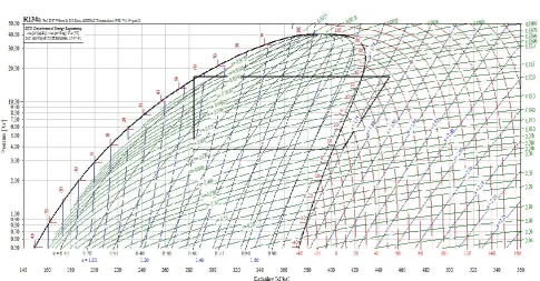
Figure 1. Prssure- enthalpy chart
6.12 Reynolds number Re = ρud/μ
6.13 Prandle number Pr= μ Cp/ k
6.14 Nusselt number
Nu = Re0.8*0.023* Pr0.4
6.15 Heat transfer coefficient inside tube Hi= Nu*k/ di
6.16 Shell side area
As=
[( )∗ ∗ ]
6.17 Shell side mass velocity
Gs=Mass flow of refrigerant/As 6.17 Equivalent diameter of shell
De = 4[Pt 2
– (π *d0 2
)]/ [π *d0] 6.18 Shell side Reynolds number
Re= De*Gs/μ
6.19 Shell side Prandtl number
Pr= μ Cp/ k
6.20 Heat transfer coefficient of shell side
H0=0.36(k/de) * Re0.55*Pr0.33*( )0.14
6.21 Overall heat transfer
Uactual=
∗
6.22 % of overdesign
= (Uactual – Uassumed / Uactual) *100
6.23 Pressure drop calculation
Shell side pressure drop = 8*jf*(Ds/De)*(L/Bs)*(ρ*u2/2)* (µ/ µw)-0.14
Tube side pressure drop = 2*jf *GS2*DS*(NB + 1)/ ρ*De* (µ/ µw)-0.14
7. Expansion valve selection
Calculation of nominal capacity
Qn=Q x Kdp x Kt
Where,
Q =Heating load
Kdp= Correction factor for pressure differential
Kt = Correction factor for liquid and evaporating temperatures 8. Evaporator design
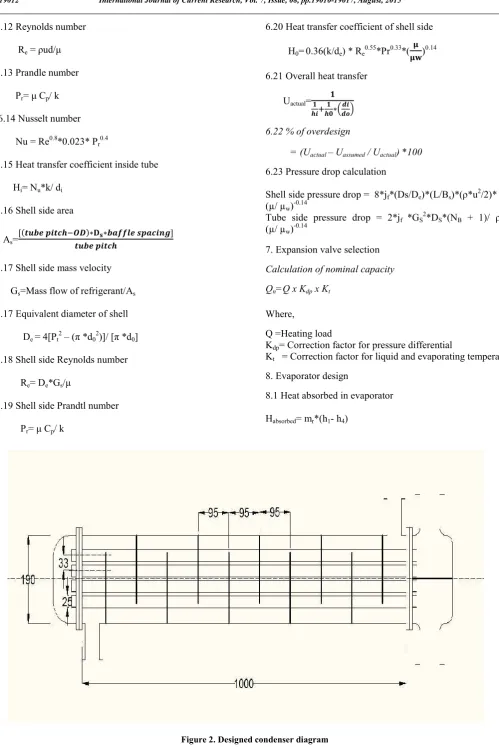
[image:3.595.40.540.33.781.2]8.1 Heat absorbed in evaporator Habsorbed= mr*(h1- h4)
Figure 2. Designed condenser diagram
8.2 Air mass flow rate
Q = m*cp*(Tambient –Tair)
8.3 Mass velocity G = m/ Amin
8.4 Reynolds number Re=G*dh/ μ
8.5 Number of tubes Nt= mr/ ρAu
8.5 Area of tube At = π*d2/ 4
8.6 Total width = 2* fin width 8.7 Total cooling from evaporator
Q = h*A*(TAIR –TDP)
19013 Jadhav et al. Performance evaluation of heat pump using simulation techniques for replacing electric water heating system to achieve energy conservation and improve IEQ in an process industry
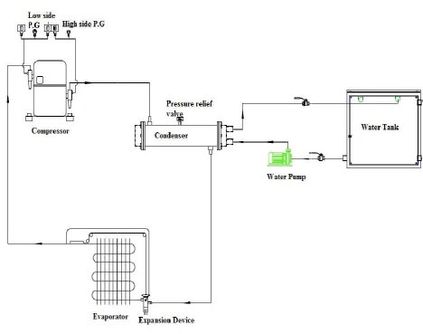
The designed condenser, compressor, evaporator and expansion valve are to be shown in above figure. The process
vapor compression system. This system is connected to washing tank replacing electric heater
II. Energy Consumption Simulation Analysis Over The
Time In Pack Calculation Pro Software
Pack Calculation is an application for comparing the yearly energy consumption of refrigeration systems and heat pumps. Among other features, trans critical CO
compared with traditional systems. The application compares different systems based on a geographical location. Traditionally, refrigeration sys
dimensioned based on a single operating point (normally somewhere around the point where the load is highest). This approach ensures that the system will deliver the cooling (or heating) required. Recently, standards for measuring
[image:4.595.85.554.372.741.2]performance of both refrigeration systems and heat pumps, have appeared. Pack Calculation Pro provides a more detailed simulation of the yearly energy consumption than the standards offer.
Figure 3. Designed heat pump system
Performance evaluation of heat pump using simulation techniques for replacing electric water heating system to achieve energy conservation and improve IEQ in an process industry
The designed condenser, compressor, evaporator and expansion valve are to be shown in above figure. The process is same as vapor compression system. This system is connected to washing tank replacing electric heater
Energy Consumption Simulation Analysis Over The Time In Pack Calculation Pro Software
Pack Calculation is an application for comparing the yearly gy consumption of refrigeration systems and heat pumps. Among other features, trans critical CO
2 systems can be compared with traditional systems. The application compares different systems based on a geographical location. Traditionally, refrigeration systems (and heat pumps) are dimensioned based on a single operating point (normally somewhere around the point where the load is highest). This approach ensures that the system will deliver the cooling (or Recently, standards for measuring seasonal performance of both refrigeration systems and heat pumps, have appeared. Pack Calculation Pro provides a more detailed simulation of the yearly energy consumption than the standards
1. Energy consumption of compressor over the year
The compressor consumption is near about 4800 kWh for the months as an averanging. For thr month april to july it goes low due lessconsumption of electricity.The consumption of compressor for januwary and december remains same.
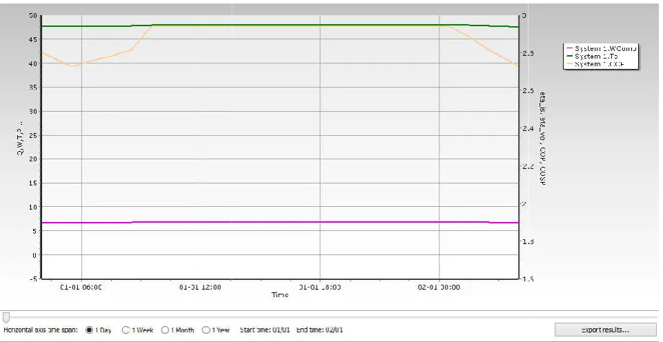
2. Simulation graph for one day
[image:5.595.46.528.49.288.2]The designed compressor capacity is 6.58 kw performance is simulated in pack calculation pro software compressor consumption capacity matches.
Figure 4.
19014 International Journal of Current Research,
1. Energy consumption of compressor over the year
The compressor consumption is near about 4800 kWh for the thr month april to july it goes low due lessconsumption of electricity.The consumption of compressor for januwary and december remains same.
compressor capacity is 6.58 kw. As the pack calculation pro software, the
The cop of the system is 3.10 near to 500 C.
3. Simulation graph for one month
The designed compressor capacity is 6.58 kw .As the performance is simulated in pack calculation pro software , the compressor consumption capacity matches .The cop of the system is fluctuates for some months .Where as the condenser can reject heat near to 500 C.
4. Energy consumption of compressor over the year
Figure 5. Simulation graph for one day
International Journal of Current Research, Vol. 7, Issue, 08, pp.19010-19017, August, 201
is 3.10. The condenser can reject heat
Simulation graph for one month
The designed compressor capacity is 6.58 kw .As the performance is simulated in pack calculation pro software , the compressor consumption capacity matches .The cop of the system is fluctuates for some months .Where as the condenser
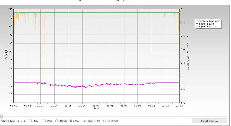
[image:5.595.47.528.317.565.2]4. Simulation graphs for one year
The compressor consumption over the year consumes 6.58 kw average. For month February to October the fluctuation occurs and it is below average. The cop of the system is in between 2.8 to 3 but it goes low in initial months and after words it is continuous. The condenser can reject heat near to 50 continuously
III. Cost benefit and energy consumption analysis
The cost benefit for heat pump, electric heater and simulated result are shown in below table. The compressor consumption can be considered for analysis.
19015 Jadhav et al. Performance evaluation of heat pump using simulation techniques for replacing electric water heating system to achieve energy conservation and improve IEQ in an process industry
The compressor consumption over the year consumes 6.58 kw average. For month February to October the fluctuation occurs and it is below average. The cop of the system is in between 2.8 to 3 but it goes low in initial months and after words it is s. The condenser can reject heat near to 500 C
ost benefit and energy consumption analysis
The cost benefit for heat pump, electric heater and simulated result are shown in below table. The compressor consumption
The above graph shows the consumption difference for electric heater and heat pump. The heat pump consumes less energy as compared to electric heater. The heat pump saves one third of energy consumption. The average compressor consumption is 7.50 kw. The electrical consumption is more .By using heat pump more amount of energy saved.
As the initial condition compressor started, the consumption is some increases and after required temperature is maintained, the compressor consumption is somewhat in steady s
[image:6.595.63.533.50.308.2]simulated results for compressor are constant for a day and is less than the heat pump consumption.
Figure 6. Simulation graph for one month
Figure 7. Simulation graph for one year
Performance evaluation of heat pump using simulation techniques for replacing electric water heating system to achieve energy conservation and improve IEQ in an process industry
The above graph shows the consumption difference for electric heater and heat pump. The heat pump consumes less energy as compared to electric heater. The heat pump saves one third of energy consumption. The average compressor consumption is lectrical consumption is more .By using heat pump more amount of energy saved.
As the initial condition compressor started, the consumption is some increases and after required temperature is maintained, the compressor consumption is somewhat in steady state. The simulated results for compressor are constant for a day and is less than the heat pump consumption.
[image:6.595.83.529.322.564.2]IV. Indoor environment quality improvement
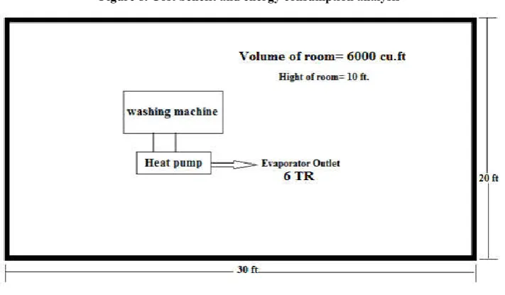
IEQ objectives vary with the programmed use for the building and industry. Each aspect of IEQ must be considered. Acoustical comfort may require specific focus because of the nature of activities inside and around the facility. For a certain prescribed noise criteria that must be provided to allow for intended operation. In design the cooling effect from evaporator is nearly 21 kW. i.e.6 tons of refrigeration.
QCooling =6 TR
The above figure shows the room dimensions for cooling from evaporator outlet. The overall dimension will be 6000 cu. ft. Heat pump can be cooled near 6000 cu.ft. Area is placed to that of heat pump. Heat pump is very beneficial in view of environmental conditions. It can maintain the IEQ of room or that work space.
V. Conclusion
Vapor compression system has been designed and electrical consumption has been worked out. The performance evaluation for heat pump has been done. The simulation results shows that
saving electrical energy units of the order of 5,86,080 kWhr/year by heat pump design where as by simulated results it comes to be 6,61,728kWh / year. The indoor environmental quality, for designed heat pump, for cooling purpose has been done for a room. The design of heat pump point 6.2 and 6.16 and 6.21 not only used for heating but also cooling the surrounding environment.
REFERENCES
ASHRAE, Handbook, “IEQ and Energy Standard for Buildings except Low-Rise Residential Buildings”.
ASHRAE, Handbook, HVAC Systems and Equipment, American Society of Heating, Refrigerating and Air- Conditioning Engineers, Inc., 1791 Tullie Circle, N.E., Atlanta, GA, USA, 2007
Donald Q. Kern 1965. Process Heat Transfer. McGraw Hill.441.
Dr. Reyad Shawabkeh. Module. Steps for design of Heat Exchanger.14.
[image:7.595.145.472.51.238.2]Durgesh J Bhatt, Prof. Priyanka M Jhavar, Prakash J Sakariya, “Review Paper on Analysis of Heat Transfer in Shell and Tube Type Heat Exchangers” International Journal for Figure 8. Cost benefit and energy consumption analysis
Figure 9. Cooling effect for a space air conditioning
[image:7.595.125.481.255.463.2]Scientific Research & Development| Vol. 2, Issue 06, 2014 | ISSN (online): 2321-0613.
Kumar, Ph.D., Member ASHRAE, and William J. Fisk, P.E., Member ASHRAE,” IEQ and the Impact On Building Occupants” ASHRAE Journal, April, 2002.
NPTEL .Module 2. Mechanical Design of Shell and Tube Heat Exchanger. 16.
Sadik Kakac, Hong tan liu (Second Edition). Heat Exchangers selection, Rating and Thermal Design. CRC Press.522.
Shikhalgar N.D., I.K. Ganechari, Rashmi Sapali, R.R. Arkererimath, S.G. Taji, “Case study on economic and energy analysis of eco-friendly heat pump system” International Conference on Recent Advances in Mechanical Engineering In collaboration with International
Journal of Engineering and Management Research
(IJEMR), Page Number: 192-195.