J. exp. Bid. (1979). 83, 59-77 5 9 With 14 figures
Printed in Great Britain
THE ROLE OF VORTICES AND UNSTEADY EFFECTS
DURING THE HOVERING FLIGHT OF DRAGONFLIES
BY STUART B. SAVAGE,
Department of Civil Engineering and Applied Mechanics BARRY G. NEWMAN AND DENIS T.-M. WONG Department of Mechanical Engineering, McGill University,
Montreal H^A 2K6, Quibec
{Received 17 August 1978)
SUMMARY
Weis-Fogh and Norberg concluded that steady-state aerodynamics is incapable of explaining how the dragonfly supports its weight during hovering. Norberg also concluded that the wing kinematics of Aeschnajuncea L., as determined photographically, are incompatible with those proposed by Weis-Fogh for his Flip mechanism. The present paper has proposed an alternative lift-generating mechanism, various aspects of which are novel from the standpoint of animal flight. Flow visualization tests performed in water established the flow field during a complete cycle of the idealized wing motion. Using this information and unsteady inviscid flow theory the forces were analysed. A plausible balance of horizontal forces and more than sufficient lift were obtained. A physical explanation of the theory is provided for those who do not wish to study the mathematical details.
I. INTRODUCTION
In an extensive review of sustained hovering flight of animals, Weis-Fogh (1973) noted that whereas in many cases the forces necessary to support the animal's weight could be explained in terms of the classical lift-generation mechanism of Kutta, Zhukovskii and Prandtl (Weis-Fogh termed this 'normal hovering'), there are other examples, such as bats, butterflies, dragonflies, hover-flies and chalcid wasps, where the required lifts are too large to be developed by the classical mechanism familiar to aerodynamicists.
In an attempt to resolve these anomalies Weis-Fogh (1973) proposed two novel mechanisms of lift generation. The first, termed the 'clap and fling', is relevant to the hovering flight of fruit-flies and chalcid wasps and at least the take-off of butter-flies, pigeons and other animals that bring their wings together on the upstroke. The 'clap and fling' mechanism was supported by the analysis of Lighthill (1973), and can operate even for the case of an inviscid fluid. In addition it does not suffer the delay in the build-up of lift associated with the Wagner effect present in the classical fttuation.
60 S. B. SAVAGE, B. G. NEWMAN AND D. T.-M. WONG
the 'flip', to explain the anomalous lift of animals such as dragonflies and hoverflie^ that hover with their bodies horizontal. The idea is that a rapid pronation of the stiff anterior portion of the wing about a spanwise axis leads to the formation of a leading edge bound vortex as well as a vortex of opposite sense at the comparatively flexible posterior part of the wing. The pronation starts at the base of the wing and propagates outwards such that the leading edge near the root would have completed its twist before the tip had started to move. Weis-Fogh felt that this spanwise delay of the twist would preserve the vorticity at the leading edge by minimizing the tip-loss effect. To produce net positive lift and no net thrust, Weis-Fogh required the wing tip to trace out an approximately rhomboidal path, with lift generated by the 'flip' mechanism along the upper and lower (nearly horizontal) paths and normal lift during the oblique up- and downstrokes. Weis-Fogh (1973) implied that hovering could not be sustained by the 'flip' mechanism if the wings beat up and down in a single plane.
Norberg (1975) filmed the hovering flight of dragonfly Aeschna juncea in the field and found that each wing beats in a single-stroke plane inclined at 6o° to the hori-zontal. In view of this the 'flip' mechanism is of doubtful relevance to the flight of the dragonfly. On the basis of the observed wing kinematics, Norberg (1975) calculated average minimum force coefficients using steady-state aerodynamics. At most only 40% of the upward force required during hovering can be explained in this way.
In the present paper some alternative lift mechanisms are proposed for the hovering flight of dragonflies. To obtain some idea of their plausibility, rough estimates are made of the forces developed during various phases of the flapping motion. The estimates are based upon mid-span wing kinematics indicated by Norberg's (1975) films. Each wing-pair is considered separately and mutual aerodynamic interference between them is neglected. The insect wings are idealized as rigid, two-dimensional, thin plates. Flow visualization experiments were performed in essentially still water with a thin plate moved to simulate the idealized wing stroke at mid-span at the appropriate Reynolds numbers, the main purpose being to identify the strengths and positions of the various vortices generated during the motion. The observed flow patterns were then modelled using unsteady potential flow theory. Using the potential flow representations the forces developed at various stages of the stroke and the net lift and thrust averaged over one complete cycle are estimated.
2. KINEMATICS OF THE WING MOTION DURING HOVERING, AND ITS IDEALIZATION
A reasonably complete description of the wing kinematics during hovering of the dragonfly Aeschna juncea may be obtained from the cine' films and still photographs taken by Norberg (1975). The exposure frequency of Norberg's cine-camera was 80 frames s- 1 whereas the average wing-beat frequency of Aeschna juncea during hovering is about 36 Hz; thus to get sufficiently detailed information over one wing-beat cycle it was necessary to patch together information from frames taken during a large number of wing beats assuming an average wing-beat frequency.
Vortices and dragonfly flight
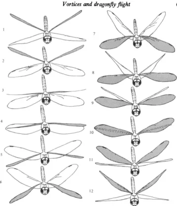
61Fig. i. Tracings from a film of Aetckiia juncca L. in free hovering flight. Axis of camera lens normal to the wing-stroke plane to within about 50. The wing-beat frequency is 37 Hz. The forewings are shaded. The pictures are ordered according to phase and selected from several wing strokes (fig. 4 of Norberg, 1975).
or changes in the insect's flapping frequency; but if the data do collapse onto a single curve there is reason to place confidence in it. Fig. 1 is taken from Norberg (1975) and represents tracings from a head-on film of a hovering Aeschna jxtncea (pictures were selected from several wing beats). From these tracings and from cine^ films taken from the side as well as still photographs, Norberg (1975) obtained the following picture of the wing kinematics. Each wing tip moves up and down in a single plane inclined at 6o° to the horizontal, and does not trace out the rhomboidal s envisaged by Weis-Fogh (1973). When viewed from the front in Fig. 1 the rewing-pair is seen to beat from 350 above the horizontal to 250 below, whereas the hindwing-pair beats from 450 above to 150 below, i.e. through total angles of
62 S. B. SAVAGE, B. G. NEWMAN AND D. T.-M. WONG
Fig. 2. Typical wing jection just inboard of the nodus of the forewing of an Aetchna dragonfly.
Pronation
Downstroke
Supinalion
Fig. 3. Schematic diagram of the idealized path of the mid chord of Aetckna juncea L. The triangle indicates the upper side of the leading edge of the wing.
60° in both cases. Other sequences showed variations from these values, so they can only be taken as roughly representative. During the downstroke the chord-line is close to horizontal while during the upstroke the chord-line is approximately vertical. At the bottom of the downstroke the wing i9 rapidly supinated and twisted. After superimposing several of the tracings from Fig. 1 of each set of wings (forewings and hindwings) near the bottom of their stroke, it was concluded that the supination takes place about a nearly stationary leading edge.
The kinematics of the pronation that takes place at the top of the stroke is not so well documented and is also less clear, because the rear portion of the wing (par-ticularly the hindwing near the root) is much more flexible when loads are applied to the convex side (see Fig. 2, which shows a typical wing section presented by Newman, Savage & Schouela (1977)). Superimposing tracings near the top of the wing stroke suggests that the forewing rotates about the leading edge whereas the hindwing may rotate about a spanwise axis close to the mid-chord line.
A schematic diagram of the complete wing stroke consisting of the downstroke, the supination, the upstroke and finally the pronation at the top of the upstroke is shown in Fig. 3.
Vortices and dragonfly flight
Time (fraction of period)
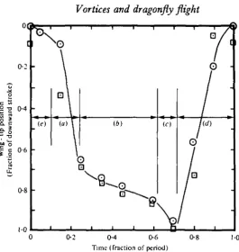
Fig. 4. Variation of wing-tip position with time as interpreted from data of Norberg (1975). The separate phases used in the nnalysis are indicated, (a) Scull, (b) pause, (c) supination,
(d) upstroke, (<•) pronation. O, left forewing; • right forewing.
[image:5.451.86.352.38.319.2]the scull) followed by a slower phase (pause). Following supination at the bottom, the upstroke takes place at nearly constant speed. Norberg (1977, private communication) has kindly supplied the authors with additional data on wing tip position obtained from his cine" film. These data for the left forewing, with the exception of a seemingly inconsistent set from four consecutive frames, substantiate the wing-tip motions indicated in Fig. 4. The relative time taken for each phase of the wing stroke is not absolutely certain, but for the analyses of the present paper the curve shown in Fig. 4 will be assumed.
For the subsequent estimates of the various forces developed during hovering, the kinematics of the mid-span has been idealized (on the basis of Fig. 4) to consist of piecewise uniform velocity segments for the scull, pause and upstroke phases con-nected by rotations at the top and bottom of the stroke corresponding respectively to pronation and supination. An average (of both fore and hindwing) chord (2a) of 1-3 cm, an average half-span of 5 cm, an amplitude of the stroke at mid-span of 2-5 cm (corresponding to a 60° flap) and a wing-stroke frequency of 36 Hz were assumed. Details of the idealized wing kinematics for the translation phases including the translation speeds, V, and corresponding Reynolds numbers, Re, are given in Table 1.
Some idea of the periods taken for the supination and pronation phases was obtained follows. Assuming that the wing comes to a halt on the downstroke prior to the pination about the leading edge and that the wing tip is approximately on the mid-chord line, then the wing tip moves downward about half a wing chord or about
6
4 S. B. SAVAGE, B. G. NEWMAN AND D. T.-M. WONGTable i. Idealized uring kinematics for translation phases
Phase Scull Pause Upstroke Fraction of wing stroke amplitude 0-63 0 1 5 i-oo
Fraction of wing stroke
period 0 1 4 039 028
Translation speed of wing at mid-span, V
(cm/s) 405
35
331
Reynolds no.
Re = zVa/v
8100 700 6420
Translation speed of water
table model (cm/sec)
27 023
2-1
The kinematic viscosities, v, of air and water were taken as 13 x io~* and icr* m'/s respectively for determination of the Reynolds number.
Table 2. Idealized wing kinematics for rotation phases
Phase Supination Pronation
Fraction of wing stroke
period O'lO 0-09 Total angle of rotation (rad) n/z ff/2 Mean rate of rotation for
insect, u> (rad/sec) 56S 628 Rotation Reynolds no.:
Re = 4<uaV
735° 8160
Mean rate of rotation for
water table model
(rad/sec) 0-33
0 3 6
13% of the wing-tip amplitude. From Fig. 4 it is estimated that the time taken for the supination is about 10% of the total wing-stroke period. The pronation at the top of the stroke takes place in the remaining 9% of the wing-stroke period. Table 2 lists the details of the idealized kinematics of the rotation phases including average rotation rate, (0, and rotation Reynolds numbers.
3. TWO-DIMENSIONAL FLOW VISUALIZATION APPARATUS AND TEST PROCEDURE
The complicated dragonfly wing motions generate a very complex flow field. Since it was intended to calculate the forces generated during hovering on the basis of inviscid flow theory, flow visualization was used to guide the theoretical modelling of the fluid motion. In particular it was necessary to determine the locations and strengths of the various vortices generated during the wing stroke so that they could be modelled by appropriate potential flow vortices in the theoretical analysis. In addition, information as to whether or not the Kutta condition was satisfied at various phases of the motion was required.
Vortices and dragonfly flight
Variable-speed d.c. motors
-Counter-weight
Fig. 5. Experimental arrangement for flow visualization tests.
Due to the large chord (15 cm) of the model and the smaller kinematic viscosity of water compared with air, the translational and rotational speeds of the model at the appropriate Reynolds numbers were considerably less than those of the dragonfly (see Tables 1 and 2).
It was awkward to determine the flow pattern after many complete cycles. There-fore it was first established that the flow pattern was essentially unchanged if each phase was preceded by at least the previous phase started from rest.
The flow was indicated by using surface markers. Several were tried: confetti comprising the residue from computer card punching operations proved to be the most successful. Time exposures were taken during the simulated flapping motions with a still camera fixed in the laboratory reference frame. Thus both the streamline patterns and magnitudes of the velocities could be determined from the direction and length of the streaks produced on the film by individual markers during a known
time exposure (typically -J s).
66 S. B. SAVAGE, B. G. NEWMAN AND D. T.-M. WONG
4. FORCES ON A TWO-DIMENSIONAL TRANSLATING AND ROTATING PLATE WHICH SIMULATES THE WING MOTION
The purpose of this section is to theoretically model each phase of the wing beat as if the wing were two-dimensional using a chord of 1 -3 cm (mean of fore and hind wing), and a flapping speed corresponding to the wing semi-span. In view of the atypical variation of chord with spanwise position when compared with, for example, a propeller, and also the preliminary nature of the calculations, a more refined choice of representative spanwise position did not seem to be appropriate. Two-dimensional, unsteady, inviscid flow theory is used and vortices are placed in the flow at positions and with strengths suggested by the flow visualization experiments.
4.1. Flow visualization and a physical explanation of the dominant forces that are generated
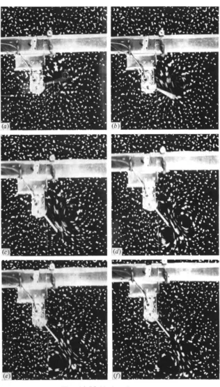
Typical results from the flow visualization tests are shown in Figs. 6-8.
A sequence of pictures showing the end rotations and downstroke is shown in Fig. 6. Fig. 6 (a) and (4) show pronation that is taken to be about the leading edge, Fig. 6(c)-(/) shows the high-speed scull, Fig. 6(g)-(k) the pause and finally 6(/)-(n) the supination. It should be noted that the plate was moved perpendicular to the supporting cross-bar, which can be seen in the pictures, and the rotations were therefore begun and ended at the appropriate angle to simulate the downstroke of a horizontal wing in a stroke plane making 60° with the vertical. The pictures were taken using a \ s exposure time and the surface markers clearly show the vortices
that are produced by the motion.
Fig. 7 was taken with the same time exposure and started from rest with supi-nation (a)-(c), followed by the upstroke (d)-(j) and prosupi-nation (k)-{l) again about the leading edge. A comparison of Fig. 6(n) and y(c) shows that the flow at the end of supination is not greatly affected by the previous motion which lends credence to the procedures which have been adopted. Fig. 8 was taken to show more clearly the flow about a rotating plate starting from rest. In this case a i s time exposure was used. Fig. 8 (a) shows the motion at the start, (b) after a rotation of 450 and (c) after 900.
In the following section these tests are used as a guide in developing theoretical analyses for the contributions to the overall force associated with each phase of the wings' motion. The force components of interest are the vertical component or lift, and the horizontal component, which is identified as a thrust if in the normal direction of forward flight, and a drag if in the reverse direction. During hovering flight the contributions to thrust and drag, of course, cancel.
Journal of Experimental Biology, Vol. 83
Fig. 6
l'"ig. 6 (a)-(/). For legend see next pnge.
Journal of Experimental Biology, Vol. 83
Fig. 6
(*)
Journal of Experimental Biology, Vol. 83
Fig. 6
On)
Fig. 6. Flow visualization of the siniulntion in water of the end rotations and downstroke of a dragonfly wing, (a)-(b) Pronation, (c)—(/) scull, (g)—(k) pause, (/)—{«) supination.
Journal of Experimental Biology, Vol. 83
Fig. 7
[image:12.451.65.382.57.612.2]Journal of Experimental Biology, Vol. 83
Fig. 7
Fig. 7. Flow visualization of the simulation in water of the end rotations and upstroke of a dragonfly wing. (a)-{c) Supination, (d)-(j) upstroke, (&)-{/) pronation.
Journal of Experimental Biology, Vol. 83
Fig. 8
(<•)
Fig. 8. Flow visualization of a rotating plate starting from rest in still water after nn angle of rotation of (a) < 50, (6) = 4 5 ° , (c) X 900.
Leading-edge vortex
Vortices and dragonfly flight 67
Flow round the
(a)
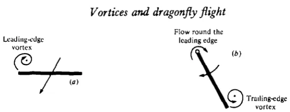
[image:15.451.77.371.42.156.2]Trailing-edge vortex Fig. 9. Sketch of flow patterns for interpreting the main contributions to the overall
force balance, (a) Pause phase, (6) supination phase.
The presence of this vortex leads to high velocities and low pressures above the plate. Thus there is a significant contribution to the overall lift. It may be noted that, since the wing is operating at a very high angle of attack (6o°), this lift would normally be associated with the conventional drag of a bluff body. However, here the associated drag coefficient is a good deal higher because the vortex is stronger and it is stationary with respect to the plate.
During the subsequent supination at the bottom of the stroke the downward movement is stopped and the plate is rotated about its leading edge. The flow is then carried round the leading edge of the plate from the lower to the upper surface as indicated in Fig. g(b).
Due to the high velocities near the leading edge, suction is generated there, giving a contribution to thrust at the start of supination and considerable lift at the end. In addition a strong separation vortex forms over the upper rear of the wing giving rise to low pressures in this region. Thus there is a further contribution to lift at , the start of supination and a contribution to drag at the end. The net contribution from the supination phase is considerable lift and less drag.
During the subsequent upstroke the vortices formed during supination are left behind the trailing edge. The wing is at an angle of attack of 300 and lift builds up in the classical manner by the shedding of trailing edge vortices and the gradual build up of circulation around the wing itself. Thus overall thrust is developed together with a smaller amount of lift.
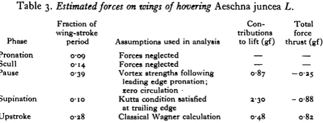
The centre of rotation for the subsequent pronation is somewhere between the leading edge and mid-chord. If it were the mid-chord no lift or thrust would be generated for a plate starting from rest. Moreover the highly cambered wing of the dragonfly is very flexible for this direction of rotation. For both these reasons the forces generated during this phase of the motion are likely to be relatively unimportant. To summarize, significant lift is generated during the pause in the downstroke and during supination, and the thrust generated during supination is approximately balanced by the overall drag generated during the upstroke. The actual values calculated for both wings during each phase of the motion are shown in Table 3.
4.2. Detailed analysis of the individual phases of the motion
Theoretical background
68
S. B. SAVAGE, B. G. NEWMAN AND D. T.-M. WONG [image:16.451.123.340.75.230.2]0 / 2a x
Fig. io. Definition sketch for analysis of translating and rotating plate.
Table 3. Estimated forces on wings of hovering Aeschna juncea L.
Phase Pronation Scull Pause Supination Upstroke Fraction of wing-stroke period 0-09 0 1 4 0-39
o-io
0-28
Assumptions used in analysis Forces neglected
Forces neglected
Vortex strengths following leading edge pronation; zero circulation • Kutta condition satisfied
at trailing edge
Classical Wagner calculation
Con-tributions
Total force to lift (gf) thrust (gf)
087
j.30
0-48
- 0 - 2 5
- 0 8 8
082 Forces listed for each phase correspond to the sum of values for fore and hind wing-pairs.
Z =
M
According to Milne-Thomson (1968), if the left-hand edge of the plate (Fig. 10) is moving with a velocity V making angle a with the * axis and at the same time is rotating with anti-clockwise angular velocity to, the complex potential without circulation is the sum of the negative powers of £ in the expression
where bars denote the complex conjugate of the function itself, i.e. excluding its argument.
In this analysis the axes are instantaneously fixed with respect to the body and flow is at rest at infinity. Thus the complex potential is
-^+-p.I
w iVa •
[image:16.451.67.397.260.386.2]Journal of Experimental Biology, Vol. 83
Fig. 11
Fig. 11. Obsen'ed flow patterns during pause phase: (a) after pronation about the lending edge, (6) after pronation about the mid chord.
Vortices and dragonfly flight 69
The addition of a counterclockwise vortex of strength 2nK0 at point z0 in the z plane adds, using Milne-Thomson's circle theorem,
to the complex potential, where £p is the point in the circle plane corresponding to
*0' . .
The stream function i/r is obtained directly from the complex potential
21^ = W-W (3) and the complex conjugate velocity
u — iv = —dW/dz in Milne-Thomson's notion. (4) The force components Fx and Fy on the plate are obtained from the general
unsteady form of Blasius' theorem
F
x- iF
v= \ip I / S *dz + DP <£ 2 dW- ip ^ <J> W dz- znKpiVe-**, (5)
where 2nK is the circulation round the plate.
Dozonstroke — scull and pause phases
Referring to Figs. 6(c)-(k) it is seen that a separation vortex grows near the leading edge of the plate and the vortices formed earlier during pronation also remain in the vicinity of the plate. The calculation of the forces generated during this short phase would therefore be difficult. An estimate of the lift generated can, however, be obtained from the analysis of Sarpkaya (1975) for the normal force on a plate started from rest and moving obliquely through stationary fluid. The total contribution to the lift from both fore and hind wing-pairs amounts to less than 10% of the all-up weight of the insect (075 gf) and this is certainly less than the accuracy of our estimation for the other phases of the motion. It therefore seems reasonable to neglect the forces for this phase of the motion.
At the commencement of the pause in the downstroke the pronation vortices have been left behind and the leading-edge separation vortex dominates the flow over the side of the plate corresponding to the upper side of the wing: it also appears to remain nearly stationary with respect to the plate. Figs. 6(g)-(k) illustrate this part of the motion following pronation about the leading edge. If pronation occurs about the mid-chord the picture is somewhat changed as can be seen in the comparison in Fig. 11.
For this phase of the motion it is therefore necessary to calculate the forces on a non-rotating plate translating obliquely at angle a (= 6o°) with a bound vortex of strength 2nK0 situated at £, and fixed relative to coordinates moving with the plate.
S. B. SAVAGE, B. G. NEWMAN AND D. T.-M. WONG
0-2a
- 0 - 2 a
0-2a
[image:20.451.47.403.50.248.2]0-2a -Q-2a 0-2a
Fig. II. Computed streamlines during pause phase near trailing edge (o, o) in coordinates fixed relative to the stationary fluid; (a) with Kutta condition satisfied, (6) without the addition of extra circulation.
Fig. 12(a). If the condition is not satisfied, on the other hand, the flow appears to travel around the trailing edge as shown in Fig. 12(6). The latter situation seems to apply in the flow visualization experiments shown in Fig. 11 (a). This may be because with the Kutta condition satisfied the flow is approaching the plate at the right hand edge and it is inappropriate to consider this as a trailing edge in this case.
Without circulation the complex potential for the flow about the plate is (equation 2 with (1) = o and addition of an external vortex)
I f . * .
The complex conjugate force (equation (5) with w = o, d/dt = o and K = o)
(6)
Evaluating the integrals by the residue theorem (Churchill, Brown & Verhey (1974))
" ' " " • (7) sin a
The average position of the vortex from the pictures after leading edge pronation is z0 = 1-380 — 1 077a (remember that the plate is moving upwards in the coordinate
system used in the theory, whereas it is moving downwards in the pictures, Fig. (>(g)-(k)). The corresponding circulation was determined by integrating the velocities around closed paths outside the viscous core of the vortex. The velocities were estimated by considering individual particle streak lengths. The circulations from the flow visualization tests were scaled to the dragonfly situation by matching th vortex Reynolds numbers, K^/v. On this basis Ko = —300 cma/s; the negative si^
Vortices and dragonfly flight
[image:21.451.83.358.51.262.2]+o +2a
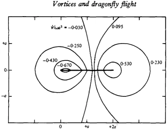
Fig. 13. Computed streamlines during supination phase in coordinates fixed relative to the stationary fluid; zero circulation.
0-2a
- 0 - 2 a
0-2a
Fig. 14. Computed streamlines during supination phase in coordinates fixed relative to stationary fluid; Kutta condition satisfied.
The rotational phases - supination and pronation
During supination the leading edge of the wing is stationary with the wing rotating about it. Moreover the wing is relatively stiff, being concave forward, for this direction of rotation. During rotation V = o in equations (2) and (5).
The flow visualization for this phase is shown in Figs. 6(/), (m), and (n) taken at a rotational Reynolds number (^coaa)/v = 3 x io4. The computed streamlines for
(
. rotating plate (Fig. 13) without circulation are in good qualitative agreement withhe flow visualization at the start of the motion (Figs. 6(/) and 8 (a)). As the plate [image:21.451.109.317.294.492.2]72 S. B. SAVAGE, B. G. NEWMAN AND D. T.-M. WONG
trailing edge and that the Kutta condition is approximately satisfied. A comparison of photographs 6(m) and 8(b) with the computed trailing-edge streamlines using sufficient circulation to satisfy the Kutta condition (Fig. 14) substantiates the latter point. Computations have therefore been made with a small vortex shed near the start of the motion and with equal and opposite circulation round the wing. The vortex strength was then adjusted to continually satisfy the Kutta condition during the subsequent motion. The angular velocity of the plate is zero at the beginning and end of the 900 motion and is assumed to vary sinusoidally with time /,
w = (oo sin (t/T)n, (8)
where T is the total time of the rotation.
The strength of the vortex and the corresponding equal and opposite circulation round the plate is continuously adjusted so that the Kutta condition is satisfied at all times.
The complex conjugate velocity dW
" £ •
and is finite at the trailing edge z - za, £ = 1 if
The complex conjugate force on the plate is obtained from equation (5) with V = o. Making frequent use of the residue theorem (Churchill, Brown & Verhey, 1974), the first term on the right-hand side of equation (5),
I r 19. ( I I ,
25o(£o£o-the second term
and the third term
The third term has unsteady terms arising from dw/dt (which is obtained from equation (8)), d^/dt and dl^/dt. The quantity dt^/dt is directly related to dzjdt, the rate of change of the position of the vortex relative to the plate. This has two parts, the first due to the velocity field relative to the plate and the second due to the reorientation of the axes as they move with the plate.
Vortices and dragonfly flight 73
1
.
l\ . '^ol
2$
Uo £2/ &>J«(S2-0
Since
it can be shown that
For the second part due to the plate rotating with counterclockwise angular velocity w
dzjdt = (o(y0-ix0) = -icoz0
Combined with equation (i) at z0, this gives
Equations 12 and 13 are combined to give
where A'o is given by equation (10).
Finally, the conjugate of equation 14 gives d^/dt and thus the force on the plate may be determined during the subsequent motion as long as the instantaneous position of the vortex £0 is known. This was obtained by integrating equation (14) numerically using small time steps of ^ViT °f t n e ^me f°r tr>e complete rotation. The forces were calculated and also summed in terms of overall lift and thrust. The starting position of the vortex was assumed to be (2a, —o-oia) at t = o. This choice was based on the experimental observations of Pierce (1961) of the vortices shed at the sharp edges of a circular plate accelerated suddenly from rest. Variations in the y position from — 0-0050 to —0-20 produced a moderate change of lift (about 15%) but a somewhat larger change of thrust (from 10 to 50%). These inaccuracies are considered to be acceptable for the present purpose.
Similar calculations have been done for the pronation at the top of the wing stroke. This is again for rotation about the leading edge. However, from the kinematics of the actual dragonfly wing it appears that the centre of rotation is closer to mid chord and for that position the contribution to lift and thrust would be zero. An additional uncertainty in the calculation of the forces for this phase of the motion stems from the comparative flexibility of the wing for this direction of rotation. On two counts therefore it is likely that the forces developed by the dragonfly during pronation are considerably less than those calculated above.
Upstroke
74 S. B. SAVAGE, B. G. NEWMAN AND D . T . - M . W O N G
at the end of supination and that both it and the supination vortex are left behind during the subsequent upstroke. Presumably the stopping vortex has added to it the starting vortex due to the upstroke and it does appear to be somewhat stronger than the supination vortex. We therefore use the classical Wagner calculation for the lift on a plate at 300 incidence bearing in mind however that the calculated forces are overestimates for two reasons:
(i) The flow is probably separated to some extent if not completely.
(ii) The dragonfly wing is comparatively pliant over the posterior position when the oncoming stream is directed towards the convex side of the wing.
Taking account of the build up of circulation, the force normal to the stroke plane
F = I 1 znapV* sin a, (15)
where r = Vt/a is the number of semi chord lengths travelled. The term in parentheses is Garrick's (1951) expression for the Wagner function.
Thus if fj is the time of the upstroke the average force normal to the stroke plane
5. DISCUSSION AND RESULTS
The calculated lifts and thrusts for each of the phases of the wing stroke are shown in Table 3. It is interesting to note that the lower rotational phase (supination) contributes significantly to the lift as anticipated by Norberg (1975). After summing over a complete wing cycle it is seen that the overall thrust is approximately zero but that the total lift is about over four times the weight (0-75 gf) of the insect. Novel mechanisms for achieving the force balance during hovering flight have been proposed and the present calculations are an attempt to determine their feasibility. It is encouraging that the calculated lift is more than adequate. Because of the great complexity of both the wing kinematics and the flow field, simplifying assumptions have been made throughout the analysis. Some of these would lead to an over-estimate of the lift.
An obvious inaccuracy is the two-dimensional representation for the flow generated by the flapping motion. There are two aspects to be considered - firstly, the three-dimensional effects associated with the finite dragonfly wing (tip losses), and secondly, the spanwise variation in the number of chord lengths each section of the wing moves during the up-and-down motion. While it is difficult to estimate the magnitude of these three-dimensional effects, the net result would likely be a reduction in total lift predicted by the two-dimensional analysis. Another inaccuracy is the neglect of mutual aerodynamic interference between the two wing-pairs. However, significant parts of the lift are generated near the bottom of the stroke when the other wing-pair is at the top of the stroke and far away. Thus the interference may be relatively unimportant.
Vortices and dragonfly flight 75
regions of the vortices developed in the flow visualization experiments. The neglect of viscous effects in the core of the vortices thus is expected to have little influence on the forces developed during the wing stroke since the viscous cores did not extend as far as the wing surface during the relevant motion.The calculations for the pronation phase show a large thrust and negative lift when the wing is pronated about the leading edge. As discussed in Section 2, the location of the axis of pronation was not clearly evident in Norberg's (1975) tracings. If the wing were rigid and pronated about the mid-chord, little lift and thrust would be expected because of the symmetry. In reality the wing is not rigid but relatively flexible for the direction of rotation associated with the pronation. In this case it is likely that the leading edge participates in the rotation but the rear portion of the wing lags behind and is activated after the wing has initiated the downstroke. Thus most of the wing is passive during the pronation phase and it is likely that the lift and thrust generated are quite small: the calculated values have not been shown in Table 3.
Because of the likely passive nature of the rear part of the wing during pronation and the initial part of the downstroke, the strength of the leading-edge vortex developed during the scull phase is probably less than that estimated ( — 300 cma/s) on the basis of the flow visualization on the rigid plate. This would result in decreased lift and thrust during the pause phase.
The theoretical model for the supination phase is probably more realistic since there appears to be clear evidence for the leading-edge rotation and the wing is relatively stiff for this direction of rotation and should be well represented by the rigid plate. On the other hand it should be noted that the theoretical model of the shed vortex is not exactly equivalent to the actual flow patterns. In the analysis it was assumed that a single vortex was shed from the trailing edge. Its strength, K, was proportional to the instantaneous rotational velocity w, thus K varied approxi-mately sinusoidally and in particular it decreased during the later phases of the motion. Physically, the strength of the vortex increases as w is increasing but certainly does not diminish as w decreases. When (o starts to decrease a 'stopping' vortex of opposite sense is shed on the opposite side of the plate. This second vortex will generate a suction force on the opposite side of the plate which reduces the net forces acting on the plate. The analytical model simulates this stopping vortex and the reduction of forces by decreasing the strength of the single 'starting' vortex. In addition we note that the strength of the shed vortex was determined by satisfying the Kutta condition at the trailing edge at any instant of time. This implies that local viscous effects near the trailing edge of the plate are unimportant in determining the circulation round the plate and the corresponding strength of the shed vortex.
76 S. B. SAVAGE, B. G. NEWMAN AND D. T.-M. WONG
During the upstroke the forces were calculated for a flat plate at 300 incidence using ideal aerofoil theory and accounting for the build up of circulation by Garrick's (1951) analysis. Firstly the effective angle of incidence may be less due to the induced effects of the vortices generated during supination. Secondly the wing is likely to be stalled, reducing the conventional 'lift' and producing high 'drag'. When these forces are resolved into horizontal and vertical components, the lift is likely to be less and the thrust about the same as those shown in Table 3 for the upstroke.
6. CONCLUSIONS
1. Weis-Fogh (1973) and Norberg (1975) conclude that steady-state aerodynamics is incapable of explaining how the dragonfly supports its weight during hovering. Norberg (1975) also concludes that the wing kinematics of Aeschna juncea L., as determined photographically, are incompatable with those proposed by Weis-Fogh (1973) for his 'flip' mechanism. The present paper has proposed an alternative lift generating mechanism, various aspects of which are novel from the standpoint of animal flight.
2. An exploratory study of the hovering aerodynamics was conducted as follows. The flow was idealized as two-dimensional and corresponded to the motion of the wing at the midspan position as inferred from Norberg's( 1975) data. Flow visualization tests on a flat plate in water at the appropriate Reynolds numbers determined this time-dependent two-dimensional flow field over a complete wing-stroke cycle. In particular the positions and strengths of vortices were determined. This information was used as the basis for modelling the flow field. The forces were analysed for each phase of the motion using unsteady potential-flow theory.
3. The force analysis produced a plausible balance of the horizontal forces but a lift force over four times the animal's weight. In view of the numerous simplifications that were made, such as the neglect of finite wing and other three-dimensional effects and the assumption of potential flow, it is not surprising that the lift was overestimated. Indeed the fact that the calculated lift is more than adequate to support the weight suggests that the essential lift-generating mechanisms have been identified.
4. During the wing stroke two phases make the major contributions to the lift and both involve novel lift mechanisms. In one, lift results from suction associated with a leading-edge vortex rotating above the wing during a pause in the down-stroke. In the other, lift is developed during supination by leading-edge suction combined with suction from a trailing-edge vortex.
REFERENCES
CHURCHILL, R. V., BROWN, J. W. & VERHEY, R. F. (1974). Complex Variables and Applications, 3rd
ed., pp. 172-179. McGraw-Hill.
GARRICK, I. E. (1951). On moving sources in non-steady aerodynamics and Kirchhoff's formula.
Proc \st U.S. vatn. Congr. appl. Mcch. pp. 733-740.
LICHTHILL, M. J. (1973). On the Weis-Fogh mechanism of life generation. J. Fluid Mech. 60, 1—17. MILNE-THOMSON, L. M. (1968). Theoretical Hydrodynamics, 5th ed., Macmillan, New York, 258-51
Vortices and dragonfly flight 77
NEWMAN, B. C , SAVAOE, S. B. & SCHOUELA, D. (1977). Model tests on a wing section of an Aeschna dragonfly. In Scale Effects in Animal Locomotion, pp. 445-477. New York: Academic Press. NOBBERC, R. A. (1975). Hovering flight of the dragonfly Aeschna juncea L. Swimming and Flying in
Nature, vol. 2, pp. 763—781. New York: Plenum.
PIERCE, D. (1961). Photographic evidence of the formation and growth of vorticity behind plates accelerated from rest in still air. J. Fluid Mech. 11, 460-64.
SARPKAYA, T. (1975). An inviscid model of two-dimensional vortex shedding for transient and asymptoti-cally steady separated flow over an inclined plate. J. Fluid Mech. 68, 109-28.