MDDSVsim: An Integrated Traffic Simulation
Platform for Autonomous Vehicle Research
Niall O’Hara, Marco Slot, Dan Marinescu, Jan ˇ
Curn, Dawei Yang,
Mikael Asplund, M´elanie Bouroche, Siobh´an Clarke and Vinny Cahill
Distributed Systems Group, School of Computer Science and Statistics, Trinity College Dublin, Ireland {niohara,slotm,dan.marinescu,jan.curn,yangda,asplunda,melanie.bouroche,siobhan.clarke,vinny.cahill}@scss.tcd.ie
Abstract—Research and development in the field of intelligent transportation systems (ITS) can be costly in terms of both time and money. A significant initial and ongoing investment is often required in order to obtain a physical platform from which experimentation and results may be gained. Simulation of entities, their dynamics and interactions can provide an appropriate and cost effective method for the development of vehicular applications.
When simulating traffic behaviour, it is modelled either at a microscopic level, where the individual characteristics and behaviours of each vehicle are reproduced, or at a macroscopic level where the traffic behaviour is aggregated and represented in terms of density, flow and speed. A difficulty with macroscopic simulation it that it often simplifies certain aspects of a scenario under investigation. Non-realistic vehicle dynamics, simplified communication models and idealistic localisation can all detract from the credibility of evaluations carried out. While microscopic simulation can alleviate these concerns, the computational re-sources required to simulate a large scale scenario, such as a highway, become prohibitive.
This paper demonstrates that the integration of a number of simulation platforms can help alleviate the aforementioned concerns. Based on this premise we present MDDSVsim, the integration of (i) VISSIM - a microscopic simulation program for multi-modal traffic flow modelling, (ii) Microsoft Robotics Developer Studio (MRDS) - a robotics simulation platform, (iii) OPNET - a discrete event simulation engine and finally (iv) The World Model, a framework for building perception systems for robots and intelligent vehicles.
I. INTRODUCTION
Self-driving cars and automated motorways have long been considered to be the ultimate solution to traffic congestion, while also cutting the number of accidents and being better for the environment. This concept was first envisaged by General Motors’ Corporation in their exhibit at the 1939 New York World’s Fair. Futurama was their notion of what the world would look like 20 years’ later [1]. In this vision, vehicles would cooperate with each other and be equipped with radio controls that would allow them to maintain closer distances to each other, akin to modern collaborative adaptive cruise control.
Much progress has been made since General Motors vi-sion from 1939. In March 2004, DARPA, the United States’ government’s Defense Advanced Research Projects Agency, came up with an initiative to help unman front-line combat operations. Part of this plan was to race autonomous robotic ground vehicles. The challenge was a disaster - out of the fifteen entries, mainly teams from US universities, the best any
of the vehicles could do was 12 km out of the 240 km course. However, it did result in waking the industry up to the idea, efforts to win the competition were significant and it attracted much attention. So much so, that when the competition was run again the following year it was a far more successful affair. With larger budgets and more experience, five vehicles were able to stay the course and complete the entire 240km with the winning team from Stanford University completing the course in just under seven hours [2]. However, it was very clear that the vehicles’ autonomy was still very limited and the algorithms were still not sophisticated enough for urban driving.
With this in mind, the 2007 Grand Challenge focused on urban driving. The controlled urban environment of an army base was the location for the Urban Challenge. Participants were tasked with ensuring complex interactions between the vehicles while also adhering to traffic regulations [3]. In just three years, technology had been sophisticated to a level that vehicles which once crashed into each other in the desert could now successfully drive autonomously on city streets.
In May 2011, Helmond in the Netherlands was the location for the first Grand Cooperative Driving Challenge (GCDC) [4], [5]. An open competition between research groups, it tasked them with creating cooperative, autonomous driving via wireless technology. The aim was to create a vehicle controller that could communicate with other vehicles, perform longitudinal control and maintain a stable platoon formation. The vehicles transmitted speeds, accelerations and locations over a wireless link and showcased the possibilities for future co-operating vehicles.
All of the aforementioned challenges showed that research and development of autonomous vehicles can be both costly and extremely challenging. The domain in which these ve-hicles must perform is highly dynamic, consisting of high speed movements and unpredictable events. Due to the sheer number of interacting subsystems involved and the volatile nature of the environment designing algorithms to deploy on these vehicles is a highly complex design problem from a software engineering point of view. Simulators are an essential tool in development of such systems, but unfortunately lacking in the key area of cooperative autonomous driving.
collabora-tive autonomous driving. The paper is laid out as follows. Section II looks at related works in the field. In section III we introduce the scenario under investigation. Section IV describes the operation of MDDSVsim and section V discusses the challenges we faced. Finally Section VI draws conclusions from our findings.
II. RELATEDWORK
Whether it be providing real-time traffic forecasting to aid in future road network planning or complex scenarios involving smart vehicles that can communicate and collaborate, large scale microscopic (per vehicle) traffic simulation models are required when developing vehicular applications [6]. On the one hand, when simulating such large scale scenarios the com-putational resources required can quickly become prohibitive. On the other hand, when simulating individual vehicles non-realistic vehicle dynamics, simplified communication models and idealistic localisation can all detract from the credibility of evaluations carried out.
In order to increase the realism of the scenario under inves-tigation combining multiple simulation platforms is a route often taken. The computational resources required can also be more easily distributed, for example, through the combination of a microscopic simulation engine and an external application domain specific engine, such as a communications network simulator. Mylonas [7] and Bhakthavathsalam [8] presented inter-vehicle communication protocols and applications that required realistic volumes of network traffic to evaluate. Through the integration of microscopic simulation programs (VISSIM, SUMO), that perform vehicular traffic flow mod-elling, and discrete event simulation engines (OPNET, NS2), that analyse communication networks and applications they demonstrated that the approach was valid when developing such applications. The authors were not concerned with the driver models in use as they were investigating the commu-nication between the vehicles. MOBYSIM [9], an integrated simulation platform, combines a number of tools including PreScan and OPNET. STRAW [10], a vehicular mobility model written for the JiST/SWANS discrete-event simulator, provides accurate simulation results based on the operation of real vehicular traffic. Genereally time steps of microscopic traffic simulators are several orders of magnitude more coarse than wireless network simulators.
[image:2.612.336.538.50.314.2]PreScan [11] is a simulator used for the development of advanced driver assistance systems. PreScan has a graphical tool that can be used to define a scenario, one or more vehicles, and their equipment. From the scenario, PreScan generates a Simulink model that can be modified to define custom vehicle behaviour. PreScan targets improvements to vehicles that involve a combination of human-machine in-terfaces and customized vehicle behaviour, particularly in terms of speed. PreScan can be interfaced with a number of external software applications such as CarSIM, which provides advanced vehicle dynamics. PreScan performs a fixed time-step simulation rather than real-time simulation. In principle, this allows PreScan to scale to a large number of vehicles
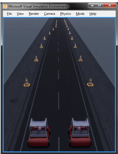
Fig. 1. Two lane scenario modelled in MRDS.
without loss of accuracy but at the expense of a potentially long computational time, with makes it impractical.
Another drawback of fixed time-step simulation compared to real-time simulation is that many events happen at exactly the same time, while this would not be the case in real-ity. This can lead to peculiar side-effects, especially in co-operative scenarios in which the vehicles are not expected to be synchronized in terms of their actions, sensor measurements, and communication. An advantage is that the accuracy of the results is independent of the performance of the host machine. A real-time simulation may need to revert to more coarse grained time steps in case it has difficulty keeping up with the clock.
III. SCENARIO
The scenario under investigation in order to validate the operation MDDSVsim consisted of two vehicles positioned side by side on a two lane stretch of road with a lane closure at a distance of 120 meters from their starting point (Fig. 1, Fig. 2). Traffic cones were placed along the route at intervals of 10 meters, the cones acted as points of reference to allow The World Model to localise each vehicle.
Fig. 2. Two lane scenario modelled in VISSIM.
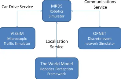
Fig. 3. MDDSVsim: The integration of three simulators and an application framework.
IV. DESIGN ANDIMPLEMENTATION
MDDSVsim is the integration of three separate software simulators VISSIM, a microscopic simulation program for multi-modal traffic flow modelling, MRDS, a robotics sim-ulation platform, OPNET, a discrete event simsim-ulation engine and a perception system framework The World Model (Fig. 3).
A. Initialisation
Initially the system is bootstrapped by loading a con-figuration file representing the scenario under investigation. The configuration contains the parameters required to launch an instance of each simulator. Because of the differences in platform, we run each of the simulators as their own processes that communicate over TCP (in case of MRDS-OPNET) and HTTP (in case of MRDS-VISSIM) and have some fairly extensive code to appropriately synchronize each simulator. Once each of the simulators has launched and have synchronised the participating vehicles are then instantiated along with any environmental models.
B. Car Drive Service
[image:3.612.337.538.57.271.2]Each instance of a vehicle has a corresponding trajectory controller process (MRDS) which indicates the path that the vehicle plans to take (Fig. 4). A custom driver model we created for VISSIM subscribes to a car drive service which allows the vehicles’ movement in MRDS to be reflected in VISSIM.
Fig. 4. Vehicle Trajectory Controller.
Fig. 5. View from inside a vehicle within MRDS.
C. Localisation Service
[image:3.612.76.274.213.342.2] [image:3.612.336.537.269.462.2]Fig. 6. Output from The World Model.
algorithm. The relative displacement is then used to estimate the global position of the vehicle in the map. The output from The World Model can been seen in (Fig. 6).
D. Communications Service
Cooperative autonomous vehicles communicate over an ad-hoc network. Within the MDDSVsim framework, communi-cation is provided by a MRDS service. To communicate with other vehicles, application code can use a library that sends messages through the communication service, and receives messages by subscribing to it. The interface provided by the service exposes MAC-layer broadcast and unicast. Network layer protocols can be implemented as libraries that are called by the application code or as separate services. Two different implementations of the communication service are available for simulated communication. The first implementation uses an external network simulator. The second implementation uses a more lightweight, local implementation based on a free-space path loss model. In both cases, the same service instance is used for all vehicles. The communication service becomes aware of which vehicles use communication when they subscribe to receive messages. The service can then inspect the state of the physical world in the simulator to obtain the actual positions of vehicles, which are used to determine whether the vehicles can communicate.
The communication service implementation that uses an external network simulator uses a custom TCP/IP protocol to connect to it. In principle, it is possible to run the network simulator on a different machine and communicate with it over a LAN or the Internet. However, the added network latency would directly influence the result of the simulation so this is not a set-up used in practice. The main reason for using TCP/IP is to improve re-usability in different simulators, since TCP/IP is available in nearly every language and platform and the protocol is simple to implement.
[image:4.612.75.277.53.129.2]We have implemented a single-user server capable of start-ing OPNET and passstart-ing messages between OPNET and the client. This implementation is reused from [14], in which the server is used to integrate directly with VISSIM. The protocol has 3 types of client to server message, and 2 types of server to client messages. The runto(time) message tells the server to execute events up until the given time, or the client that the server is done running an its next event is at the given time. The msg(source, destination, arrival time, payload) message from client to server triggers a unicast of the payload from source to destination or a broadcast
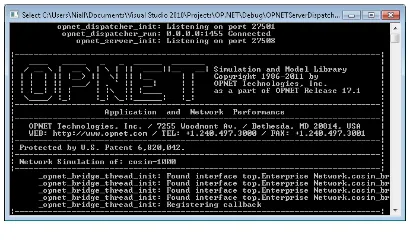
Fig. 7. OPNET.
from source if destination is -1. For every vehicle able to receive the unicast or broadcast, the server sends a msg(source, destination, arrival time, payload) message to the client, with destination set to the identifier of the receiver and arrival time to the point in time at which OPNET computed the reception. A reception will also result in the server sending a runto message, which serves to give back control to the client. The reception might result in new events at the client that are to be executed before the next OPNET receive event. Finally, the client constantly sends move(node, enabled, x, y, speed, orientation, time) events to the server to update the position of the given node used in the network simulator and whether the node is still enabled. Speed and orientation are mainly used to extrapolate the position from the last position update.
The node identifiers used by OPNET are different from those in the main simulator. OPNET does not support dynam-ically creating a new node. Instead, there is a pre-defined pool of nodes that are enabled and disabled by move messages. In a simulation where vehicles are continuously created and removed, the same OPNET node identifier might be used mul-tiple times for vehicles that exist in different, non-overlapping periods of time. The translation between identifiers in OPNET and the main simulator is implemented on the client. The identifiers used in message (’source’, ’destination’, ’node’) correspond to those in OPNET. A future implementation might use a second translation on the server-side and use an intermediary format for identifiers, to simplify transitioning to other network simulators.
In a real-world setting, the communication service imple-mentation can be replaced by one that uses an actual 802.11p adapter. In this case, every vehicle has its own instance of the communication service.
V. LESSONSLEARNED
We have found it to be highly challenging to integrate different simulators. Some necessary integration steps can reduce the scale or accuracy that is achievable using the simulators, or the ease of developing new protocols.
A. Positioning and control
wheels over a surface with friction. The resulting movement and position of the vehicle depends on the accuracy of the physics simulation, which in part depends on the performance of the computer, and is thus non-deterministic. While MRDS does offer the possibility of making absolute position updates, doing so can interfere heavily with the physics simulator. Controlling vehicles in MRDS can be somewhat challenging, as it ultimately involves setting the speed and rotation of individual wheels, though utility libraries with higher-level abstractions such as trajectories are available. We therefore use the MRDS positions as authoritative throughout the simulators and replicate them to VISSIM (to the extent possible given the limited API), and OPNET. The control over position in OPNET is relatively straight-forward as it calls a user-defined function that returns a position of a node whenever it needs one. However, position updates to OPNET are periodic, so the function uses extrapolation of the last position, which may lead to slight inaccuracies. In general, those lie in the millimetre range and should not have a significant effect on the outcome of simulations.
B. Synchronisation of events
The simulators also use a fundamentally different model of time and events. VISSIM updates the positions of all vehicles in iterations that move simulation time forward by a fixed amount of at least 100ms. The driver model of vehicles in VISSIM is invoked at each 100ms time-step. This means that any event that leads to a change in a vehicle’s behaviour may have to wait up to 100ms of simulation time to be passed to VISSIM by the driver model, and another 100ms to be reflected in the position of the vehicle computed by VISSIM. OPNET is a discrete-event simulator. Simulation events are ordered by pre-set execution times, and events are generated by other events. OPNET uses 64-bit floating point numbers to represent time, allowing for extremely fine-grained time steps. MRDS is executed in real time. The positions of vehicles are updated as fast as the computer can update the graphical display and perform physics simulation for each of the vehicles, which leads to variable time steps. When the time steps in between iterations become large, the fidelity of physics simulation degrades substantially, which means it is imperative that the software and the hardware on which it runs allow for a reasonably high iteration (frame) rate. We found 20Hz to be reasonably safe. Another implication is that VISSIM and OPNET will have to keep up with MRDS, meaning the rate at which simulation time needs to move forward in both of these simulators is at least as fast as real time. This limits the scale of the simulation that can be performed. The accuracy of OPNET’s fine-grained model of time is partly lost in real-time synchronization, since events are executed in small batches in order to keep up with the rate of execution of MRDS. Positions in VISSIM cannot always be correctly kept in sync with the other simulators due to the inherent delay in updating the driver model.
C. Application design
The application logic is primarily implemented within the MRDS framework, which means the that application is ex-ecuted as an instance of a service that communicates with other services for sensing and communication. This has the benefit of making logic in the simulator portable to real robots, but also comes with some drawbacks inherent to the MRDS platform. Application logic can either be executed in response to incoming sensor results, received messages, or as events scheduled at a particular time. However, MRDS does not give any real-time guarantees and uses multiple threads, so events may be late and out-of-order. Robotics or vehicle controllers are typically real-time systems with precise control over timing. There is currently no way to simulate that behaviour within the MRDS framework. The World Model library was relatively straight-forward to integrate and was implemented as a library that is exposed as another MRDS service. The benefits of using a service interface is that the world model can easily replace existing MRDS sensors, but the drawback is that the complex data structures of the world model need to have serialisable wrapper classes defined to translate them into a service interface.
D. Software integration
A more practical problem when integrating different sim-ulators is their platforms, programming languages, and APIs, which represent 3 different generations of Windows runtime environments. MRDS is programmed in C#, which runs in the .NET Common Language Runtime. All MRDS logic is executed as a set of services, which can communicate over HTTP. VISSIM is programmed in C++ and can either load a DLL for the driver model, or be accessed by an external process over the Windows COM interface. However, only the former gives direct control over vehicles, and has the previously mentioned limitations. OPNET is programmed in C and compiles to Native Win32 code. While it is straight-forward to program new protocols in OPNET using its GUI, the API for interacting with OPNET from the outside is highly restrictive. Code that is linked to the OPNET binary needs to re-implement the main event loop and can then generate OPNET events that can read from a pointer. This is sufficient to pass arbitrary information between OPNET and other simulators, but makes it difficult to perform deeper integration.
Integrating different simulators proves to be highly complex. The properties of one simulator impact what can be achieved in other simulators and complete synchronization is not always feasible, particularly given real-time time constraints and lim-ited APIs.
VI. CONCLUSION
autonomous driving, but none address the combination of traffic, sensing, control, and wireless communication in a rigorous fashion. We have integrated a microscopic traffic simulator (VISSIM), with a robotics simulator (MRDS), a communication network simulator (OPNET), and a sensor data processor (World Model), and developed a basic cooperative autonomous driving scenario using the integrated simulation environment. Each simulator provides visibility into a different aspect of the scenario. We have identified a set of design challenges that we ran into during the development process, some of which limit the scale and accuracy of the simulations. We present this as a case-study in moving towards practical evaluation of cooperative autonomous driving scenarios.
ACKNOWLEDGMENT
This work was supported, in part, by Science Foundation Ireland grant 10/CE/I1855 to Lero - the Irish Software Engi-neering Research Centre (www.lero.ie)
REFERENCES
[1] G. Automotive. (2009, june) Gm futurama pt 1. YouTube. Accessed 19-September-2012. [Online]. Available: http://www.youtube.com/watch? v=eNlgfkE9nWA
[2] S. Thrun, M. Montemerlo, H. Dahlkamp, D. Stavens, A. Aron, J. Diebel, P. Fong, J. Gale, M. Halpenny, G. Hoffmann,et al., “Stanley: The robot that won the darpa grand challenge,”The 2005 DARPA Grand Challenge, pp. 1–43, 2007.
[3] J. Bohren, T. Foote, J. Keller, A. Kushleyev, D. Lee, A. Stewart, P. Vernaza, J. Derenick, J. Spletzer, and B. Satterfield, “Little ben: The ben franklin racing team’s entry in the 2007 darpa urban challenge,” pp. 231–255, 2009. [Online]. Available: http: //dx.doi.org/10.1007/978-3-642-03991-1\ 6
[4] E. van Nunen, M. R. J. A. E. Kwakkernaat, J. Ploeg, and B. D. Netten, “Cooperative competition for future mobility,”Intelligent Transportation Systems, IEEE Transactions on, vol. 13, no. 3, pp. 1018 –1025, sept. 2012.
[5] K. Lidstrom, K. Sjoberg, U. Holmberg, J. Andersson, F. Bergh, M. Bjade, and S. Mak, “A modular cacc system integration and design,”
Intelligent Transportation Systems, IEEE Transactions on, vol. 13, no. 3, pp. 1050 –1061, sept. 2012.
[6] M. Jha, G. Gopalan, A. Garms, B. Mahanti, T. Toledo, and M. Ben-Akiva, “Development and calibration of a large-scale microscopic traffic simulation model,” Transportation Research Record: Journal of the Transportation Research Board, vol. 1876, no. -1, pp. 121–131, 2004. [7] Y. Mylonas, M. Lestas, A. Pitsillides, and P. Ioannou, “Speed adaptive
probabilistic flooding for vehicular ad-hoc networks,” inPersonal In-door and Mobile Radio Communications (PIMRC), 2011 IEEE 22nd International Symposium on, sept. 2011, pp. 719 –723.
[8] R. Bhakthavathsalam, S. Nayak, and M. Srikumar, “Expediency of penetration ratio and evaluation of mean throughput for safety and com-mercial applications in vanets,” inUltra Modern Telecommunications Workshops, 2009. ICUMT ’09. International Conference on, oct. 2009, pp. 1 –5.
[9] M. van Noort, B. van Arem, and B. Park, “Mobysim: An integrated traf-fic simulation platform,” inIntelligent Transportation Systems (ITSC), 2010 13th International IEEE Conference on, sept. 2010, pp. 1301 – 1306.
[10] D. R. Choffnes and F. E. Bustamante, “An integrated mobility and traffic model for vehicular wireless networks,” in Proceedings of the 2nd ACM international workshop on Vehicular ad hoc networks, ser. VANET ’05. New York, NY, USA: ACM, 2005, pp. 69–78. [Online]. Available: http://doi.acm.org/10.1145/1080754.1080765
[11] F. Hendriks, M. Tideman, R. Pelders, R. Bours, and X. Liu, “Develop-ment tools for active safety systems: Prescan and vehil,” inVehicular Electronics and Safety (ICVES), 2010 IEEE International Conference on, july 2010, pp. 54 –58.
[12] J. Curn, D. Marinescu, and V. Cahill, “A flexible approach to man-agement and processing of collaborative vehicular perception data,” in
Proceedings of the Workshop on Emergent Cooperative Technologies in Intelligent Transportation Systems at the 2010 IEEE Intelligent Transportation Systems Conference 2010, Sept. 2010.
[13] R. B. Rusu and S. Cousins, “3D is here: Point Cloud Library (PCL),” inProceedings of the IEEE International Conference on Robotics and Automation (ICRA), Shanghai, China, May 9-13 2011.