Original citation:
Papaefstathiou, E., Kerbyson, D. J., Nudd, G. R., Atherton, T. J. and Harper, J. S. (1997) An introduction to the layered characterisation for high performance systems. University of Warwick. Department of Computer Science. (Department of Computer Science Research Report). (Unpublished) CS-RR-335
Permanent WRAP url:
http://wrap.warwick.ac.uk/61021
Copyright and reuse:
The Warwick Research Archive Portal (WRAP) makes this work by researchers of the University of Warwick available open access under the following conditions. Copyright © and all moral rights to the version of the paper presented here belong to the individual author(s) and/or other copyright owners. To the extent reasonable and practicable the material made available in WRAP has been checked for eligibility before being made available.
Copies of full items can be used for personal research or study, educational, or not-for-profit purposes without prior permission or charge. Provided that the authors, title and full bibliographic details are credited, a hyperlink and/or URL is given for the original metadata page and the content is not changed in any way.
A note on versions:
The version presented in WRAP is the published version or, version of record, and may be cited as it appears here.For more information, please contact the WRAP Team at:
An Introduction to the Layered Characterisation
for High Performance Systems
E. Papaefstathiou
D.J. Kerbyson
G.R. Nudd
T.J. Atherton
J.S. Harper
December 3, 1997
Abstract
A toolset for performance analysis of parallel systems, PACE, is presented in this report. In this toolset expert knowledge about the performance evaluation tech-niques is not required as a prerequisite for the user. Instead a declarative approach to the performance study is taken by describing the application in a way that is both intuitive to the user, but can also be used to obtain performance results. The under-lying performance related characterisation models and their evaluation processes are hidden from the user. This document describes the special purpose language, and the evaluation system, that form the core of the PACE toolset. Amongst the aims of the toolset is the support of characterisation model reusability, ease of experimentation, provide different levels of prediction accuracy, and support of different levels of characterisation model abstraction.
1
Introduction
Performance evaluation is an active area of interest especially within the parallel sys-tems community. A large number of performance tools have been developed to assist the system developer, the application programmer, and the tuning expert to select the most efficient combination of hardware and parallelisation strategy [6, 11, 12, 13]. However, the use of performance tools typically require an advance knowledge of per-formance related issues, which is usually not commonly understood. The purpose of the characterisation work at Warwick is the development of prediction, and analysis of, methodologies and tools that will allow non performance specialists to undertake performance studies. PACE is a set of tools aimed to assist the users to undertake performance studies. In this document a special purpose language and an evaluation system is presented that form the core of the PACE performance toolset.
The notion of performance tools for the “rest of us” is the central driving force behind Warwick’s characterisation work. In order to achieve this goal, the user of the performance methodology must focus his/her effort on the aspects of the performance study that does not require performance related speciality. The user of performance tools usually knows the application but does not have any knowledge of the perfor-mance methodologies. The characterisation toolset presented here requires the user to describe the application that is under investigation in a way that is both intuitive
to the user but can also be used in the performance study. The performance related characterisations and their evaluation process, are hidden from the user.
The characterisation methodology provides the following features:
Characterisation Model Reusability Allows the definition of the control flow of the
application and the computation/communication pattern in a hardware indepen-dent way.
Easy Experimentation Allows easy experimentation with different hardware
plat-forms and parallelisation strategies.
Different Levels of Prediction Accuracy Supports different levels of characterisation
from high level parametric characterisation (e.g. measuring floating point oper-ations), providing moderate accuracy, to low level instruction level characterisa-tion, providing high accuracy of predictions.
Different Levels of Model Abstraction Can be used in different stages of software
development cycle and different type of software development projects (e.g. the porting of serial code or developing parallel software from scratch).
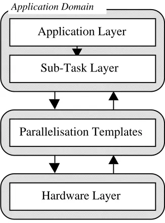
The PACE toolset is based on a characterisation framework [7, 8, 9, 14]. This framework is a layered approach that separates out the hardware and software systems through the use of a parallelisation template, figure 1. This modular approach leads to readily re-usable models which can be interchanged in experimentation. For instance the performance predictions across parallelisation techniques can be compared for a particular application on a particular hardware. The layers used are detailed below:
an application layer, which describes the application in terms of a sequence of
sub-tasks using control flow graphs. Each node of the graph can be a sequential processing node, a user defined parallel sub-task, or a parallel processing generic (from a library).
an application task layer, which describes the sequential part of every
sub-task within an application that can be executed in parallel. The result of the evaluation of these models is fed to the parallel template layer.
a parallel template layer, that describes the computation-communication pattern
and other hardware resource usage.
a hardware layer, which is responsible for characterising the communication and
computation abilities of the system.
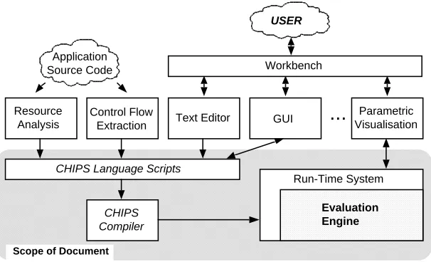
The PACE toolset contains a number of separate programs integrated under a com-mon graphical user interface. The organisation of these components is shown in fig-ure 2. The main components of this toolset are:
A set of special purpose language scripts suitable for the description of
perfor-mance aspects of parallel systems.
A run-time system that contains an evaluation engine.
A compiler that translates the scripts into object code.
A set of interface tools which allow the extraction of control flow/resource
Application Layer
Sub-Task Layer
Parallelisation Templates
Hardware Layer
[image:4.595.216.379.128.348.2]Application Domain
Figure 1: The Layered Characterisation Framework
A further set of graphical interface tools that allow the user to define aspects of
the performance study and visualise the outputs.
The PACE run-time system is responsible to perform basic maintenance operations such as the loading of PACE compiler output, the evaluation of models, and the storage of the results. The run-time system also includes the evaluation engine that is used to combine and evaluate the models of the performance study. The user will be able to ex-amine the results through a visualisation module and experiment with the performance parameters. A number of pre-defined performance analysis studies will be provided such as scalability and bottleneck analysis.
An automated procedure is provided to extract from the user’s application the con-trol flow and resource requirements from the user’s application. Additionally the re-source usage of each node of the control flow graphs is identified in terms of a high level language, or instruction level operations. The resource usage information is com-bined with the control flow information and converted to PACE language scripts.
The user will be able to edit his/her own PACE language scripts and use a graphical interface to design the computation/communication pattern of the parallel algorithm used, and the control flow of an application that has not yet been developed. After the development of PACE scripts have been concluded for a performance study the PACE compiler will translate the scripts to object code.
The scope of this document is to present the PACE language, the run-time system, and the evaluation engine.
Resource Analysis
Control Flow
Extraction Text Editor GUI
Parametric Visualisation
...
Application Source Code
USER
CHIPS Language Scripts
CHIPS Compiler
Evaluation Engine
Run-Time System
Scope of Document
[image:5.595.146.449.126.310.2]Workbench
Figure 2: PACE Tool Organisation
description is presented. The language is presented in BNF format and the semantics of it’s constructs are explained. In Section 5 an example is given for predicting the performance of a parallel sorting kernel. Finally in Section 6 a summary and a number of extensions that will be included in future versions of the language are described.
2
Objects and Object Interfacing
A program written in the PACE language includes a number of objects. Each object is one of the following types: application, subtask, parallel template, and hardware. These are used to describe the performance aspects of the respective system components. An object is comprised of:
Internal Structure The internal structure is defined by the programmer and is hidden
from the other objects. This structure contains various types of procedures that describe the control flow of the application, the form of any regression models, and computation-communication structures.
Options The objects, depending on their type, have a number of pre-defined options
that determine the default behaviour of the object. The default values of these options can be set in the object, and can be modified by other objects. For ex-ample an option might include the default hardware or parallelisation strategy (parallel template) that will be called by a subtask.
Interface Objects include an interface that can be used by other objects to modify
Template Subtask Hardware Template Subtask Application Hardware Template Application Hardware Subtask Application
User User User
[image:6.595.140.450.123.283.2]Application Object Interface Subtask Object Interface Template Object Interface Write Read Interface Operations w w r/w r/w r w r/w r w r r
Figure 3: Object Interfacing
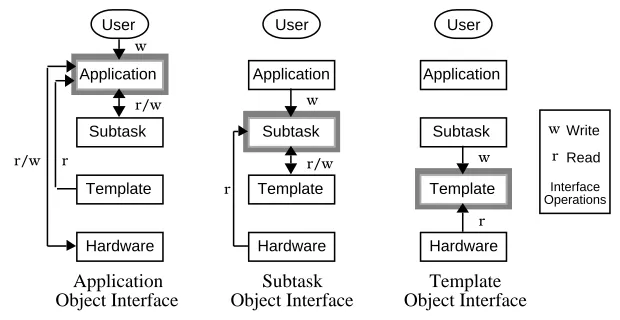
Objects of a certain type can only read from, and write to, certain other object types as shown in figure 3. An object can read an external variable of other objects only if it is in a lower level of the layered approach hierarchy. Further rules that govern this relationship are described below:
Application Type Object A PACE program includes only one object of the
applica-tion type. This is the object that is called automatically from the run-time system of the PACE run-time system (i.e. the entry point of a PACE program). The external interface of the application object can be used by the user, through the PACE run-time system, to manipulate parameters of the performance study (e.g. change the size of the problem). The application object can modify the external variables of subtask and hardware objects and also use entire subtask objects. For example, a parallel sort application object can use constituent quicksort and bitonic sort subtask objects but only modify the processor configuration of the underlying hardware platform, without directly calling it.
Subtask Type Object A PACE program might include many subtasks. The interface
of a subtask object can be modified by the application object. A subtask can modify the external variables and use template objects. For example the bitonic sort is an object of the subtask type that can be used by the application object, it can modify the external variables and use the bitonic parallel template object.
Parallel Template Type Object A program might include many parallel template
ob-jects. Their interface can be manipulated by subtask obob-jects. The parallel tem-plate can not modify the interface of any other object type. The parallel temtem-plate object describes the computation-communication patterns and the use of other hardware resources.
The PACE environment provides some special purpose objects that have extended semantic features. These include a template with the nameseq(or sometimesasync) that covers the case of the execution of a subtask on a single CPU. Also an object calledhardwarewill contain a common interface to all hardware platform parameters (e.g. number of processors). This will allow the reference to the hardware objects independently of the type of the parallel system in use. Finally a special case is the object Eval, which contains parameters related to the status of the PACE run-time system and evaluation engine. An object can query the status of PACE by examining theEvalobject.
For each object type a detailed description is given in the following paragraphs:
2.1
Application Object
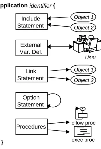
A PACE program contains one application object. The object acts as the entry point of the performance study, and includes an interface that can be used by the user through the PACE run-time system to modify parameters of the performance study (e.g. data dependent parameters, hardware platforms to be used). Additionally the application object combines the subtask objects using either control flow graphs or execution pro-cedures. An application object includes the following parts (figure 4):
Include Statements Declares the subtask, parallel template, and hardware objects that
will be used by the application object.
External Variable Definitions Defines the external variables that will be the interface
between the application object and the user through the PACE run-time system.
Link Statements The purpose of the link statement is to modify external variables and
options of the subtask objects and the hardware objects being used.
Options Sets the default options of the application object. These options can be also
modified by the user through the PACE run-time system.
Procedures The procedures describe the relationships of the subtasks in order to
pre-dict the performance of any serial parts of the application. This relationship can either be described as control flow graphs (cflow) or execution statements (exec). Control flow graphs are defined in terms of graph components, where as execu-tion statements are more flexible allowing complex relaexecu-tionships to be expressed. The application object must include an execution procedure namedinit. This procedure is the entry point to the program.
2.2
Subtask Objects
The subtask objects represent parts of an application that are parallelised on a hardware platform using a specific parallelisation strategy. The subtask objects in an application are combined by the single application object.
A subtask object includes the evaluation of the sequential parts of the parallel pro-gram. It also includes the mapping of these sequential parts of the application onto the computation-communication pattern described in the parallel template object.
Include Statement
application identifier {
Object 1
Object 2
Link Statement
Object 1
Object 2
External Var. Def.
User
Option Statement
Procedures
}
cflow proc
[image:8.595.213.386.123.378.2]exec proc
Figure 4: Application Object Structure
strategy for a hardware platform. During an execution of a PACE program only one template might be evaluated for each subtask.
The subtask object has the same structure as the application object (as shown in figure 4). The role of theinitprocedure in a subtask object is to specify the execution time of the serial part of the subtask when linked into the parallel template. The pres-ence of theinitfunction is optional in the subtask objects. Aninitfunction might not be required when the serial parts of the subtask are constant and can be specified directly in the link statement.
Application Obj
Proc1
Init Map
Proc n
...
Subtask Obj
ParTmp Obj 1
ParTmp Obj 2 Execution Time
Figure 5: The Evaluation Process of a Subtask Object
[image:8.595.185.409.541.619.2]currently active parallel template object that was specified by the optioncommand in the subtask object or in the application object. Finally, the current parallel template object is called and evaluated. The results of the parallel template object evaluation is the execution time of the subtasks which is returned to the application object.
2.3
Parallel Template Objects
The parallel template object describes the computation-communication pattern and al-lows access to the hardware devices of a system. The syntax of the parallel template objects is similar to the application and subtask objects with the exception of the state-mentlinkand the existence of additional statements for exec procedures.
The parallel template objects do not manipulate the interface of any of the other objects so there is no need for the existence of thelinkstatement. The computation-communication pattern is expressed in terms of stages and steps. A stage is a plete phase of the parallel algorithm and might include many computations and com-munications. In many cases a parallel template might have many stages of the same computation-communication pattern. The number of stages in a parallel template ob-ject is defined using the optionnstage. The evaluation procedure is shown in figure 6. The parallel template object provides an interface to the resources in the hardware object. When evaluated this allows the application object to specify hardware resource usage. The serial execution time can be calculated in any object with the use of cflow procedures. This indirectly involves the hardware models for a single CPU. However, all the other resources including the system inter-connection network, input/output de-vices, etc., are accessed through the parallel template objects. This is done by describ-ing the steps in a stage. Each step corresponds to an access to one or more hardware resources, e.g. for computation the CPU, for inter-processor communication the com-munication network, and for retrieval of data hard disks.
Subtask Obj
Proc1 Init
Proc n
...
Partmp Obj
Hardware Obj map
* nstage
Application Obj Tx
Figure 6: Parallel Template Evaluation Procedure
the source processor, and the destination processor. This configuration can be repeated many times during the same step in order to describe a complete communication pat-tern.
3
The Run-Time Environment
The run-time system provides the tools needed to produce performance predictions from a set of PACE scripts representing a single modelled application. Each PACE object must be entered into a separate file; the name of the file should be the name of the object with an .la suffix appended to it. For example, an object calledasyncwould have a PACE script called async.la. Once all of the PACE objects in the model have been defined they are compiled using the PACE compiler and then linked together to form a single executable program. This program can then be executed to evaluate the model and give predictions of its performance.
3.1
The Compiler
Each PACE object is compiled into a standard linkable object file. Due to the way in which objects link to each other it is necessary to compile the parallel template objects before the subtask obects, and the subtask objects before the application object.
The shell command chip3s is used to compile each PACE program, for example, the following command compiles a PACE script called foo.la into a linker object called foo.o,
$ chip3s foo.la -o foo.o
The other compiler options available can be listed by giving the -help option to the compiler. Once all of the PACE objects have been compiled, the chip3sld command is used to link them into a single program. For example to link the compiled object files app.o, sub.o and tmp.o into a single model called app the following command would be used.
$ chip3sld -o app app.o sub.o tmp.o
This creates an executable program, called app, that contains the performance ob-jects making up the overall model. The program also contains the evaluation engine needed to produce performance predictions about the modelled application.
3.2
The Evaluation Engine
The evaluation engine evaluates the compiled PACE objects, combining the results to produce detailed predictions of the performance of the whole application. Each time the program is executed the models are evaluated and a set of predictions produced for the current problem configuration (i.e. the set of application parameters).
$ app Nproc=16
When a model is evaluated it outputs the performance predictions it computed to the standard output stream. By default, only the overall time taken is printed, preceded by the textTx =. For example,
$ app Nproc=16 Tx = 1.44154e+07
However, each evaluation produces much more detailed predictions than this. Us-ing different command-line options when evaluatUs-ing a model, it is possible to access these other predictions.
-proc-table Output a table listing predictions for each processor.
-list-segs List each CFLOW procedure and the time that it is predicted to take.
-list-compat List the communication pattern of the model.
-trace Output PICL format trace information into a file ending in .trf
There are also a number of debugging options available, these are useful for finding errors in the PACE programs and for examining how the evaluation engine actually works. Use the-? option to the executable model to find out exactly what types of debugging information is available (look at the-debugoption).
4
Language Description
This section presents the syntax and the semantics of the PACE language. The descrip-tion includes:
The definition of the object types, the role of each object and a road-map to the
structure of the object (section 4.1).
The object header is described in detail (section 4.2). The statements included in
the object header include the interface definition, the setting of parameters of the objects that will be used by the current object and setting of the configuration of the object.
The control flow procedure syntax is described in section 4.3. These procedure
describe the control flow of a part of an application in terms of a graph notation.
The statement of execution procedures are presented in section 4.4.
The data representation and manipulation statements are described in section 4.5.
The syntax of the language is described in BNF form. The non-terminal symbols are presented in italics and the terminal symbols in bold. A special symbolis used to
4.1
Object Definition
application def ! application identifierf
include lst vardef lst link stm option stm proc lst
g
subtask def ! subtask identifierf
include lst vardef lst link stm option stm proc lst
g
partmp def ! partmp identifierf
include lst vardef lst option stm proc lst
g
There are four types of objects representing each layer of the layered approach methodology. Three of them can be defined the PACE language. The user can define, in each performance study, one application object and a number of subtask and parallel template objects.
The purpose of the application object is to provide an entry point for the perfor-mance study, to include the interface that can be used in the run-time system by the user, and finally to combine the subtask objects of the performance study using control flow and execution procedures.
The subtask object represents a part of the application that has been parallelised with a specific parallelisation method. The subtask includes the evaluation of the serial parts of the parallel task and the linking of these serial parts onto a parallel template. The subtask might link with more than one parallel templates in cases where the sub-task needs to use different parallel algorithms for different hardware platforms or when an experimentation is required to determine the most efficient parallel algorithm. How-ever, during an evaluation of the performance study only one parallel template is used per subtask.
exec procedures are used to represent the stages and steps of the parallel algorithm and the use of the hardware devices.
The PACE language does not support the definition of hardware objects from within the language syntax. The hardware objects must be defined using the C programming language. The interface of the hardware object must be defined in order for the applica-tion, subtask, and parallel templates objects to read and modify hardware parameters.
4.2
Object Header
include lst ! include stm
or include lst include stm
or
include stm ! include identifier ;
vardef lst ! vardef stm
or vardef lst vardef stm
or
vardef stm ! var type : var lst ;
var lst ! var opt
or var lst , var opt
var opt ! assignment stm
or identifier
type ! numeric
or vector
or string
link stm ! linkflink bodyg
or
link body ! link opt
or link body link opt
link opt ! identifier : assignment lst
option stm ! optionfoption bodyg
option body ! assignment lst
or option body assignment lst
procedure lst ! procedure def
or procedure lst procedure def
or
procedure def ! proc cflow
The include statement is required to declare the use of other objects (for reading or modifying their parameters). The PACE compiler reads the symbol file of the object used as parameter in the include command. The symbol file contains the type of the object and the external variables of the object.
The vardef statements define the variables before their use. These parameters might be interface variables accessed by other objects, global to the object by hidden by other objects, and locals to procedures. The var statement declares the variables that will be used.
The link statement allows an object to modify the interface parameters and options of other objects. This is the method supported by PACE for inter-object communi-cation. The objects that their parameters will be modified should be defined with the include statement prior to the link statement. The parameters that will be modified must have been defined in the vardef statements of the objects.
There are a number of rules concerning the type of the objects that can be manip-ulated. The application object can modify subtask and hardware objects, the subtask object can modify template and hardware objects, and finally the parallel template is not allowed to modify any objects.
The option statement allow the setting of the objects configuration. Each object de-pending on each type have a number of pre-defined options such as the default hardware platform, the setting of the debugging mode etc. These options can be also modified by other objects with the link statement. The available options are:
hrduse A string value, valid in application or subtask objects. It controls hardware model selection and must be defined somewhere.
nstage A numeric option that can be set in parallel templates. It sets the number of times the stage is repeated.
ptmuse A string option that can be used in subtask objects to select the parallel tem-plate to be used.
There are two types of procedures supported: the cflow and the exec procedures. The cflow procedures represent the control flow of a piece of software. The compiler evaluates the cflow procedures using a graph evaluation algorithm. The output of the cflow procedures is an expression that predicts the execution time of the software that the cflow procedure represents. The exec procedure includes execution statements for looping, branching, etc. which can be run in a similar fashion to a general purpose language code. Execution procedures are included in the PACE language to enable non control flow evaluations to take place.
4.3
Control Flow Procedures
proc cflow ! proc cflow identifier argument lstfvardef lst cflow lstg
cflow lst ! cflow stm
or cflow lst cflow stm
or
or loop stm or case stm or call stm or fcflow lstg
compute stm ! compute vector ;
loop stm ! loop ( vector , expression ) cflow stm
call stm ! call call type opt identifier ;
or call call type opt identifier ( expression lst ) ;
call type opt ! cflow
or exec
or
case stm ! case ( vector )fcase lstg
case lst ! case opt
or case lst case opt
case opt ! expression : cflow lst
argument lst ! argument lst , argument opt
or
argument opt ! var identifier lst ;
The compiler analyses the cflow procedures using a graph analysis algorithm and outputs the evaluation expression of the control flow graphs. The procedures return the time required to execution the part of the application represented by the control flow description. The definition of the procedure includes an identifier that is the name of the procedure and an optional list of arguments that can be passed from the caller. Arguments are passed by value and can only be numbers.
An important aspect of the characterisation is the formation and use of the descrip-tion of the system resources also known as resource models [10]. The resource models are coupled with information about the application tasks in terms of resource usage information, which are termed resource usage vectors. The resource models are em-bedded in the hardware object definitions and are invisible from the user. However, the resource usage vectors are application specific and are defined by the user in the control flow procedures. A resource usage vector is associated with each statement that represents the control flow of the application.
The cflow statements are:
compute represents a processing part of the application. The argument of the state-ment is a resource usage vector. This vector is evaluated through the current hardware object. The result of the evaluation is the execution time required for the processing stage.
overhead per iteration. The main body of the loop statement includes a list of the control flow statements that will be repeated.
call is used to execute another procedure. This procedure might be either cflow or exec procedure. The result returned from this procedure is added to the total execution time of the current control flow procedure.
case includes an argument which is the resource usage vector that represents the over-head of this statement. The body of the statement includes a list of expressions and corresponding control flow statements which might be evaluated. The ex-pressions represent the probability of the corresponding control flow to be exe-cuted.
4.4
Execution Procedures
proc exec ! proc exec identifier argument lstfvardef lst exec lstg
exec lst ! exec stm
or exec lst exec stm
or
exec stm ! fexec lstg
or assignment stm ;
or if ( cond expr ) exec stm if else opt
or while ( cond expr ) exec stm
or for ( assignment stm ; cond expr ; assignment stm )
exec stm or break ;
or continue ;
or print expression lst ;
or call call type opt identifier ;
or call call type opt identifier ( expression lst ) ;
or return ;
or return expression ;
or exit ;
or dim identifier , expression ;
or free identifier ;
or step identifier step proc lstfexec lstg
or confdev expression lst ;
if else opt ! else exec stm
or
step proc lst ! on expression
or on expression , expression
or on expression , expression , expression
or
trans-lated directly to the corresponding statements in the target language. Each object might contain an exec procedureinitthat is the entry point of the object. This procedure is called upon any reference to the object that includes it.
The PACE language supports the while statement for looping operations. It requires an expression as an argument. This is the condition that as long as it is true the loop is executed. Two related statements are the break and the continue. These statements are valid when executed inside a loop. The break statement terminates the loop indepen-dently of the condition of the while statement. The continue statement causes the next iteration of the enclosing loop to begin.
For conditional branching the if else statement is supported, the else clause is op-tional. There is also the call statement that is similar to the one used in the control flow functions. However, only exec procedures are allowed to be called. Also a procedure might be called implicitly while its name is used in an expression. In this type of call both cflow and exec procedures can be used.
The return statement determines the end of the execution of the current procedures and the return of the execution of the procedure that has called the current executing procedure. If return includes an expression argument the results of the expression if returned to the caller procedure. The exit command terminates the execution of the performance study and returns control to the PACE run-time system.
The dim and free statements provide dynamic vector allocation support. The dim statement creates a data vector (not a resource usage vector). The first argument is the name of the vector and the second the size of the vector. The free statement de-allocates the vector. Additionally assignment and print statement are supported.
The step and confdev statements are applicable only in parallel template objects. Each pattern might contain more than one stage and each stage more than one step. Each step corresponds to the use of one of the hardware resources of the system. The first argument in the step command is the name of the device that will be used during the step. The available devices of the current hardware platform are listed in the hard-ware symbol file that is used with the include statement in the beginning of the object definition. The devices that have been defined in this symbol file have the type hrddev. The second argument of the step statement is optional. It can be used to define the set of processors affected by this step. It can have up to three numerical expressions, the first being thefirst processor in the set, the second being the last processor, and the third being the stride.The code body of the step statement is to configure the device specified in the current step.
A step statement must not include other embedded step statements. The configura-tion of the device is performed with the confdev statement. The arguments of this state-ment is a list of expressions. The meaning of these argustate-ments depend on the device. For example the device cpu accepts only one argument which is the execution time of a processing stage. The device inpcom (inter-processor communication) accepts three arguments the message size, the source, and the destination processors. The confdev statement in the case of the inpcom device can be used many times to describe a com-plete communication pattern. Other hardware devices might include access to a storage device or communication between parallel systems across HiPPi networks etc.
4.5
Data Representation and Manipulation
assignment stm ! identifier = expression
expression lst ! expression opt
or expression lst , expression opt
expression opt ! expression
or string cost
or
expression ! expression + expression
or expression – expression or expression * expression or expression / expression or – expression
or + expression
or ( expression )
or variable
or identifier ( expression lst ) or identifier ( )
or number
cond expr ! expression>expression
or expression>=expression
or expression<expression
or expression<=expression
or expression==expression
or expression!=expression
variable ! identifier
or identifier [ expression ] or identifier . identifier
vector ! vector const
or identifier
vector const ! <is identifier , expression lst>
or <0>
string const ! ” string char ”
The language supports three data types: numeric, one dimensional vectors, and strings. These can be represented either as constants or variables. Variables must be declared before used, by the var statement. The scope of the variable might be externally visible to other objects, external in the object but hidden from other objects, and finally local to a procedure. The attributes of the variable is again determined with the var statement.
PACE provides a dynamic approach for defining the type of vectors. The user has the ability to define additional vector types by specifying the type of the vector and the elements that can be included. This definition is done by an additional tool, the vector definition tool (mkrsus), that converts the user definition to a vector specification file that is used by the PACE compiler during the compilation stage. Attributes of a vector type are the number of elements of the vector. A vector can have either a fixed or variable number of elements. Each element can be a number, a symbol, or a combination of both. An example definition of the data vectors in the tool follows:
(* Array numeric vector *) def data {
args variable; type numeric; }
An example definition of a resource usage vector for floating point operations can be defined as follows:
(* Floating point operation resource usage vector *) def flop {
args variable; type combination;
{ add, sub, mul, cmp, div, sqr, exp, sin, other } }
The flop vector has a variable number of elements but its element might be an expression that includes numeric values and/or symbols. The symbols are defined as the type of floating point operation (add, subtraction, etc.).
The expressions can only include numeric values. The expressions support the+,
,,arithmetic operations, unary , the call of cflow, exec, or pre-define
mathe-matical procedure, the reference to any numeric variable.
A variable can be an identifier referring to a local to the object variable, an element of a data vector, and an external to the object variable. In this case the scope must be defined first and then, separated with a dot, the name of the parameter must be identified. The string constants and variables can be only used for output purposes.
4.6
Miscellaneous
assignment lst ! assignment
or assignment lst , assignment
or
vector ! identifier
or vector const
5
Characterising a Sorting Kernel
An example of using the PACE language to develop a characterisation performance model is shown below. The application under consideration is a sorting kernel based on the Batcher’s bitonic sort. The kernel developed for a transputer based Parsytec SuperCluster. The are a number of phases for the execution of this kernel:
Data Load A number of data elements are stored on the hard disk of the host
work-station. Part of the data is loaded into the memory of each transputer.
Serial Sorting The data elements in the local memory of each processor are initially
sorted using a serial sorting algorithm, which in this case is quicksort.
Merging The sorted data elements on each processor are merged with the bitonic
al-gorithm in order to create a overall sort list.
Data Store The sorted array is stored onto the hard disk of the host workstation.
In this example, only the merging part of the sort is considered. The PACE program consists of: an application object memsort, that combines the serial sort with the merge procedures; the serial subtask object qsort (that is not presented here); the subtask object merge that uses the bitonic parallelisation strategy; and the parallel template object bitonic. The example illustrates the use and interfaces between objects of all types. It is not intended to provide the results of a performance study. The source code of the application object is described first.
5.1
Application Object
1 (*
2 * memsort.la - Parallel memory sorting 3 *)
4 application memsort {
5 include qsort; (* Qsort subtask *)
6 include merge; (* Merge subtask *)
7 include hardware; (* Hardware parameters *)
8 include parsytec; (* Parsytec hardware model *)
9 (* Interface and global variables *)
10 var numeric:
11 Nelem = 262144, (* # of elements *)
12 Nsize = 4, (* size of element *)
13 Nproc = 16; (* # of procs *)
14 (* Linking to other objects *)
15 link {
16 hardware:
17 Nproc = Nproc;
18 qsort:
20 ModelCh = 2;
21 merge:
22 Nelem = Nelem,
23 Nsize = Nsize;
24 }
25 (* Options *)
26 option {
27 hrduse = "parsytec";
28 }
29 (* Entry point procedure *)
30 proc exec init {
31 call qsort;
32 call merge;
33 }
34 }
The application object,memsort, begins with its name definition in line 4, followed by the object header (lines 5–28), and finally the main body (lines 29–34).
Initially the objects used are defined in lines 5–8 with the include statement (the memsortobject uses the subtask objectsqsortandmergeand the generic hardware object).
The definition of the parameters that can be modified by the user through the PACE run time system follows in lines 9–13. These are the number of elements to be sorted (Nelem), the size of each elements in bytes (Nsize), and the number of processors (Nproc). The modification of parameters in the other objects being used is specified in lines 14–24 (using the link statement). Initially (lines 16–17) the hardware object parameterNprocis set to the number of processors. It should be noted that the pa-rameter Nproc has the same name in both the application and the hardware objects. However, there is no scope conflict since the parameter on the left of the assignment belongs to the hardware object and the parameter on the right belongs to the applica-tion object. Similarly the parameters are set for the qsort and the merge subtask objects (lines 18–23).
Only one option is set in this example, the hrduse option specifies that this appli-cation must use the object calledparsytecto provide the hardware characterisation (lines 25–28).
The last part of the object is theinitexecution procedure. This is the entry point of the object (and the performance study as a whole). In this case, it calls theqsort andmergeobjects.
5.2
Subtask Object (
merge)
1 (*
2 * merge.la - Parallel merge (bitonic) sort 3 *)
4 subtask merge {
6 include hardware; (* Generic hardware object *)
7 (* Interface *)
8 var numeric:
9 Nelem = 4096, (* Elements to be sorted *)
10 Nsize = 4, (* Size (bytes) of each element *)
11 dtpp, (* Data per processor *)
12 Pmrg; (* Prob. to exit merge loop *)
13 (* Linking to other objects *)
14 link {
15 bitonic:
16 Ndata = dtpp,
17 Clen = Nsize,
18 Tx = Txsort();
19 }
20 (* Options *)
21 option {
22 ptmuse = "bitonic";
23 }
24 (* Entry point procedure *)
25 proc exec init {
26 var numeric: Pmrg0 = 0.639, Pmrg1 = 0.793;
27 dtpp = Nelem / hardware.Nproc;
28 (* Linear regression model for merge prob. *)
29 Pmrg = Pmrg0 + Pmrg1 / hardware.Nproc;
30 }
31 (* Main seg for merge function *)
32 proc cflow Txsort {
33 var vector:
34 start = <is clc, 3*IASG>,
35 merge = <is icc, 169, 20>,
36 tlcp = <is ct, 6.03>,
37 otcp = <is clc, FOR, IASG, ICMP, 2*IADD,
38 4*VIDX, 2*FASG>;
39 compute start;
40 loop (<0>, 2*dtpp*Pmrg)
41 compute merge;
42 loop (<0>, 2*dtpp*(1-Pmrg))
43 compute tlcp;
44 loop (<0>, dtpp)
45 compute otcp;
46 }
The source code of themergeobject begins with the subtask name definition (line 4) and continues with the object header (lines 5–23), and the proceduresinitand Txsort(lines 24–46). The execution time for the merging is calculated by the control flow procedureTxsort.
Initially the use of thebitonicparallel template object and the generic hardware object (lines 5–6) are declared. The interface parameters are defined in lines 7–12. These are: the number of elements to be sorted (Nelem), the size of each element (Nsize), and the probabilitiy for the merge software execution graph in the Txsort procedure (Pmrg0). The parameters for the objectsbitonicandseqare set in lines 13–19. For the bitonic object the number of elements (Ndata), the size of each element (Clen), and the execution time required for each merge (Tx) are set.
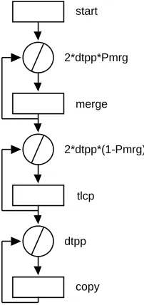
Theinitprocedure (lines 24–30) calculates the parametersdtpp(data elements per processor) andPmrg(the probability for the merge loop to be finished in theTxsort control flow graph). The control flow procedure Txsort (lines 31–46) evaluates the graph shown in figure 7. The resource usage of the graph nodes is defined in lines 34–38. These are vectors and include different types of resource usage information. The parametersstartandotcpare high level language resource usage vectors, the parameter tlcpis execution time, and the parametermerge is an instruction level resource usage vector. The control flow graph is described in lines 39–45. The com-pute statement accepts one argument which is a resource usage vector while the loop statements first argument is a resource usage vector representing the loop overhead per iteration, and the second argument defines the number of repetitions. In all cases the loop overhead has been considered zero.
start
merge
tlcp
copy 2*dtpp*Pmrg
2*dtpp*(1-Pmrg)
[image:23.595.125.226.414.628.2]dtpp
Figure 7: Control Flow Graph for Merge
5.3
Parallel Template (
bitonic)
2 * bitonic.la: Bitonic parallel template 3 *)
4 partmp bitonic {
5 include hardware; (* Parsytec object hardware *)
6 include Eval; (* Chips system parameters *)
7 (* Interface *)
8 var mpruv:
9 Tx = 0; (* Execution time *)
10 var numeric:
11 Ndata = 1024, (* Number of data *)
12 Clen = 4, (* Size of elements *)
13 dtpp, (* Data per processor *)
14 Comseq; (* Value of GetDest *)
15 (* Options *)
16 option {
17 nstage = Log(2, hardware.Nproc), seval = 1;
18 }
19 proc exec GetDest
20 var phase, src;
21 {
22 var numeric: group, dist, dest;
23 group = Power(2, Eval.nstage + 1);
24 dist = Power(2, phase - 1);
25 if( Mod(src, dist * 2) < dist )
26 dest = src + dist;
27 else
28 dest = src - dist;
29 if (Mod(src, group) >= group / 2) {
30 if (dest < src)
31 Comseq = 0;
32 else
33 Comseq = 1;
34 } else {
35 if (dest < src)
36 Comseq = 1;
37 else
38 Comseq = 0;
39 }
40 return dest;
41 }
43 proc exec EvalStage {
44 var numeric:
45 phase, ptrg, psrc;
46 phase = Eval.nstage;
47
48 while (phase > 0) {
49 step inpcom {
50 psrc = 0;
51 while (psrc < hardware.Nproc) {
52 ptrg = GetDest(phase, psrc);
53 if (Comseq == 0)
54 confdev psrc+1, ptrg+1, dtpp;
55 psrc = psrc + 1;
56 }
57 }
58 (* And then processing time *)
59 step cpu {
60 confdev Tx;
61 }
62 step inpcom {
63 psrc = 0;
64 while (psrc < hardware.Nproc) {
65 ptrg = GetDest(phase, psrc);
66 if (Comseq == 1)
67 confdev psrc+1, ptrg+1, dtpp;
68 psrc = psrc + 1;
69 }
70 }
71 phase = phase - 1;
72 }
73 }
74 (* Entry point *)
75 proc exec init {
76 dtpp = Round(Clen * Ndata);
77 (* Evaluation of stage *)
78 call EvalStage;
79 }
80 }
The execution procedureGetDest(lines 19–41) determine the source and target processors for a specific stage and phase of the algorithm. The procedure is called by EvalStagebefore defining each communication configuration. The procedures accepts two arguments, the current phase and the source processor and it returns the destination processor.
The execution procedureEvalStage is defined in lines 42–73. It describes the computation-communication pattern of the bitonic template for each stage of the parallel algorithm. The algorithm has a number of communication and computation steps in each stage. The communication steps are described in lines 49–57 and 62– 70. The while loop determines the number of communication steps (which depends on the current stage of the algorithm). The parameters of each communication step are calculated in the while loop, and set in lines 54 and 67 with the confdev statement. The first argument of this statement is the size of the communication, the second is the source processor, and the third is the destination processor. In lines 58–61 the computation step is defined. The confdev statement in line 60 determines the time required for this computation phase.
The procedureinitis executed for each stage (lines 74–79). It determines the number of data strored in the local memory of each processor and calls the execution procedureEvalStage.
6
Summary and Future Extensions
A performance language and a run-time environment have been presented that do not require a user to have expertise in the relevant performance evaluation methodologies. The user, with the performance language, can describe the software and the paralleli-sation strategies in a way that is both intuitive and more importantly can be used in the performance study.
A number of future extensions will be incorporated into future versions of the PACE language. These include:
Bottleneck Analysis The operations and use of hardware resources can be analysed
by ranking them in order of time costs. By doing this, the predominant classes of operations can be identified as bottlenecks in the overall performance of the system. Such an analysis can be incorporated as a future extension to the PACE toolset. This is being investigated within the PEPS project [3].
Overlapping Computation-Communication One of the features of modern parallel
systems is the ability to overlap the computation and the communication stages of an algorithm. This is a feature that is not currently supported by PACE and requires extensions in the syntax of the parallel template and extensions to the hardware models to support asynchronous communication.
Multi-threaded Processing The parallel template currently assumes that all
Language Syntax Extensions for Different Topologies One of the issues that effect
the re-usability of the parallel template objects is the mapping of the commu-nication pattern onto the network topology. This currently can be achieved by the explicit use of different user procedures to handle communication patterns for different inter-connection network topologies. A support of this feature from within the syntax of the language will enforce the re-usability of the parallel template objects.
Library of Generics Warwick’s characterisation work includes the examination of a
range of application areas in order to identify the computational core (also termed generics) which are common across several applications [2]. Ten generics have been selected, including curve fitting, fast fourier transform, matrix multiplica-tion, etc., and have been further characterised [4]. A model library of generics will be developed for the PACE language, which can be used as subtask compo-nents in future application studies.
The PACE language, by providing characterisation model reusability, allows easy experimentation, supports different levels of accuracy of predictions, and different lev-els of model abstraction to assist the system developer, the application programmer, and the performance expert. It can be used to perform a wide range of performance studies. The main concept of PACE is the development of a performance tool for the “rest of us” that will allow the users to perform performance studies.
References
[1] E. F. Gehringer, D. P. Siewiorek, and Z. Segall. Parallel Processing: The Cm* Experience. Digital Press, 1988.
[2] Parallel Systems Group. Characterisation of processing needs. Final Report D5.1, ESPRIT 6962 — Performance Evaluation of Parallel Systems (PEPS), 1993.
[3] Parallel Systems Group. Analysis of bottlenecks. Interim Report D5.4, ESPRIT 6962 — Performance Evaluation of Parallel Systems (PEPS), 1994.
[4] Parallel Systems Group. Parallelisation of generics. Interim Report D5.3, ESPRIT 6962 — Performance Evaluation of Parallel Systems (PEPS), 1994.
[5] L. H. Jamieson, D. Gannon, and R. J. (Eds.) Douglas. Characterizing Parallel Algorithms. MIT Press, 1987.
[6] B. P. Miller, M. Clark, J. Hollingsworth, S. Kierstead, S. S. Lim, and T. Torewski. IPS-2: The second generation of parallel program measurement system. IEEE Trans. Parallel and Distributed Systems, 1(2):206–217, 1990.
[7] G. R. Nudd, E. P. Papaefstathiou, Y. Papay, T. J. Atherton, C. T. Clarke, D. J. Kerbyson, A. F. Stratton, R. F. Ziani, J., and Zemerly. A layered approach to the characterisation of parallel systems for performance prediction. In Proc. of the Performance Evaluation of Parallel Systems Workshop (PEPS ’93), pages 26–34, Coventry, U.K., November 1993.
[9] E. P. Papaefstathiou, D. J. Kerbyson, and G. R. Nudd. A layered approach to parallel software performance prediction: A case study. In Proc. International Conference Massively Parallel Processing, Delft, Holland, June 1994.
[10] E. P. Papaefstathiou, D. J. Kerbyson, G. R. Nudd, and T. J. Atherton. Compar-isons of resource models within a parallel system characterisation framework. submitted to Parallel Computing, 1994.
[11] M. Parashar, S. Hariri, and G. C. Fox. An interpretive framework for application performance prediction. Technical Report SCCS-479, Syracuse University, USA, 1993.
[12] D. Pease et al. PAWS: A performance evaluation tool for parallel computing systems. IEEE Computer, pages 18–29, January 1991.
[13] D. A. Reed, R. Aydt, T. M. Madhyastha, R. J. Nose, K. A. Shields, and B. W. Schwartz. An overview of PABLO performance analysis environment. Technical report, University of Illinois, USA, 1992.
A
YACC Grammar
%{ /*
* Project : CHIPS Compiler
* File : chips.y
* Purpose : Compiler Parser Specification
* $Id: chips.y.tex,v 1.1 1997/12/01 17:02:56 john Exp $ */
%}
%union {
char* string; /* String token value */
float number; /* Number token value */
}
%token APPLICATION SUBTASK PARTMP INCLUDE VAR LINK OPTION PROC %token CFLOW COMPUTE LOOP CALL CASE
%token EXEC IF ELSE WHILE FOR BREAK CONTINUE PRINT %token RETURN EXIT DIM FREE STEP CONFDEV
%token NUMERIC VECTOR STRING MPRUV IS %token GTE LSE EQL NEQ
%token ON
%token <string> IDENTIFIER STRCONST %token <number> NUMBER
%nonassoc LOWER_THAN_ELSE %nonassoc ELSE
%left EQL NEQ
%left '<' '>' GTE LSE %left '+' '-'
%left '*' '/'
%nonassoc UMINUS UPLUS %nonassoc EXPLST
%%
/*
* Program definition */
program: sbt_obj
| apl_obj
| ptm_obj
;
/*
* Object definition */
sbt_obj: subtask_hd obj_body
ptm_obj: partmp_hd obj_body
obj_body: '{' include_sec vardef_stm link_stm
option_stm procedure_lst '}' ;
subtask_hd: SUBTASK IDENTIFIER
;
apl_hd: APPLICATION IDENTIFIER
;
partmp_hd: PARTMP IDENTIFIER
;
/*
* Object Header */
/* Include statement */
include_sec: include_lst
;
include_lst: /* Empty */
| include_lst include_stm
;
include_stm: INCLUDE IDENTIFIER ';'
| INCLUDE error ';'
;
/* Link statement */
link_stm: /* Empty */
| link_hd link_body '}'
;
link_hd: LINK '{'
;
link_body: link_opt
| link_body link_opt
;
link_opt: link_hd assignment_lst ';'
| link_hd error ';'
link_hd: IDENTIFIER ':'
| error ':'
;
/* Option statement */
option_stm: /* Empty */
| option_hd assignment_lst opt_semi '}'
;
option_hd: OPTION '{'
;
/* A do-nothing optional semi-colon for option stmts */
opt_semi: /* Empty */
| ';'
;
/*
* Procedure definitions */
procedure_lst: /* Empty */
| procedure_lst proc_cflow
| procedure_lst proc_exec
;
/*
* Execution Procedures */
proc_exec: exec_hd argument_lst '{' vardef_stm exec_lst '}'
;
exec_hd: PROC EXEC IDENTIFIER
;
exec_lst: /* Empty */
| exec_lst exec_stm
;
exec_stm: assignment_stm
| return_hd ';'
| return_hd expression ';'
| call_stm
| EXIT ';'
| dim_stm
| FREE IDENTIFIER ';'
| print_stm
| while_stm
| for_stm
| BREAK ';'
| if_stm
| step_stm
| confdev_stm
| error ';'
| error '}'
;
/* Assignment Statement */
assignment_stm: assignment_opt ';' ;
assignment_opt: string_assign
| numassign
| vctassign_hd vector_const
| vctassignel_hd expression
;
string_assign: IDENTIFIER '=' STRCONST ;
numassign: numassign_hd expression
;
numassign_hd: IDENTIFIER '='
;
vctassign_hd: IDENTIFIER '='
;
vctassignel_hd: vctasgel_hd expression ']' '=' ;
vctasgel_hd: IDENTIFIER '['
;
assignment_lst: assignment_opt
| assignment_lst ',' assignment_opt
| error ',' assignment_opt
;
/* Dim statement */
dim_stm: dim_hd expression ';'
;
dim_hd: DIM IDENTIFIER ','
;
print_stm: print_hd print_lst ';' ;
print_hd: PRINT
;
print_lst: /* NULL */
| print_lst ',' expression
| print_lst ',' STRCONST
| STRCONST
| expression
;
/* While statement */
while_stm: while_hd while_cnd exec_compound
;
while_hd: WHILE '('
;
while_cnd: expr_cnd ')'
;
/* For statement */
for_stm: for_hd '(' for_pre ';' for_cnd ';'
for_post ')' exec_compound ;
for_hd: FOR
;
for_pre: numassign
;
for_cnd: expr_cnd
;
for_post: numassign
;
/* Conditional statement */
if_stm: if_hd '(' if_cnd ')' exec_compound
%prec LOWER_THAN_ELSE
| if_hd '(' if_cnd ')' exec_compound
if_else exec_compound ;
if_hd: IF
if_cnd: expr_cnd ;
if_else: ELSE
;
/* Parallel template statements */
step_stm: step_hd step_mid exec_lst '}'
;
step_hd: STEP IDENTIFIER
;
step_mid: step_mid_hd expression_lst '{'
| '{'
;
step_mid_hd: ON
;
confdev_stm: confdev_hd cdev_arg_lst ';'
;
confdev_hd: CONFDEV
;
cdev_arg_lst: expression %prec EXPLST
| cdev_arg_lst ',' expression %prec EXPLST
;
/* Other exec definitions */
return_hd: RETURN
;
exec_compound: '{' exec_lst '}'
| exec_stm
;
/*
* Control Flow Procedures */
proc_cflow: cflow_hd argument_lst '{' vardef_stm
cflow_lst '}' ;
cflow_hd: PROC CFLOW IDENTIFIER
;
cflow_lst: /* Empty */
;
cflow_stm: compute_stm
| call_stm
| loop_stm
| case_hd '(' case_cost ')' '{' case_lst '}'
| error ';'
| error '}'
;
loop_stm: loop_hd '(' loop_cost loop_cnt ')' cflow_compound
;
loop_hd: LOOP
;
loop_cost: vector ','
;
loop_cnt: expression
;
compute_stm: compute_hd vector ';'
;
compute_hd: COMPUTE
;
call_stm: callproc_hd ';'
| callproc_hd '(' expression_lst ')' ';'
;
callproc_hd: CALL CFLOW IDENTIFIER
| CALL EXEC IDENTIFIER
| CALL SUBTASK IDENTIFIER
| CALL IDENTIFIER
;
case_hd: CASE
;
case_cost: vector
;
case_lst: case_opt
| case_lst case_opt
;
case_opt: case_pro cflow_lst
case_pro: expression ':' ;
cflow_compound: '{' cflow_lst '}'
| cflow_stm
;
/*
* Variable and Argument Definition */
argument_lst: VAR identifier_lst ';'
|
| VAR error ';'
;
vardef_lst: /* Empty */
| vardef_lst vardef_opt
;
vardef_opt: VAR vartype ':' var_lst ';'
;
vardef_stm: vardef_lst
;
var_lst: var_opt
| var_lst ',' var_opt
| error ',' var_opt
;
var_opt: IDENTIFIER
| assignment_opt
;
/*
* Data Presentation & Manipulation */
vartype: NUMERIC
| VECTOR
| STRING
| MPRUV
;
expression_lst: expression %prec EXPLST
| expression_lst ',' expression %prec EXPLST
;
expression: expression '+' expression
| expression '*' expression
| expression '/' expression
| '-' expression %prec UMINUS
| '+' expression %prec UPLUS
| '(' expression ')'
| variable
| expproc_hd expression_lst ')'
| expproc_hd ')'
| NUMBER
;
/* Conditional expression */
expr_cnd: expression cnd_op expression
;
cnd_op: '>'
| '<'
| GTE
| LSE
| EQL
| NEQ
;
variable: IDENTIFIER
| vctidx_hd expression ']'
| IDENTIFIER '.' IDENTIFIER
;
vctidx_hd: IDENTIFIER '['
;
expproc_hd: IDENTIFIER '('
;
vector: vector_const
| IDENTIFIER
;
vector_const: vector_hd const_lst '>'
| '<' NUMBER '>'
;
vector_hd: '<' IS IDENTIFIER ','
;
/* List of constants / RSUS id's */
const_lst: const
| const_lst ',' const
const: NUMBER
| const_id_mult IDENTIFIER
;
const_id_mult: /* Empty */
| NUMBER '*'
;
/*
* Miscellaneous Definitions */
identifier_lst: IDENTIFIER
| identifier_lst ',' IDENTIFIER
| error ',' IDENTIFIER
;
B
Lexical Analyser
%{ /*
* Project : CHIPS Compiler
* File : chips.l
* Purpose : Compiler Lexical Analyser
* $Id: chips.l.tex,v 1.1 1997/12/01 17:02:53 john Exp $ */
%}
%x COMMENT STRST
id [A-Za-z][A-Za-z0-9`]*
number ([0-9]+|([0-9]*\.[0-9]+)([eE][-+]?[0-9]+)?)
ws [ \t]+
nl \n
%%
"(*" BEGIN COMMENT;
<COMMENT>. ; <COMMENT>\n ;
<COMMENT>"*)" BEGIN INITIAL;
\" BEGIN STRST;
<STRST>[^\"]* {
yylval.string = strdup(yytext); return STRCONST;
}
<STRST>\" BEGIN INITIAL;
application { return APPLICATION; }
subtask { return SUBTASK; }
partmp { return PARTMP; }
include { return INCLUDE; }
var { return VAR; }
link { return LINK; }
option { return OPTION; }
forward { return FORWARD; }
proc { return PROC; }
cflow { return CFLOW; }
compute { return COMPUTE; }
loop { return LOOP; }
call { return CALL; }
case { return CASE; }
exec { return EXEC; }
if { return IF; }
while { return WHILE; }
for { return FOR; }
break { return BREAK; }
continue { return CONTINUE; }
print { return PRINT; }
return { return RETURN; }
exit { return EXIT; }
dim { return DIM; }
free { return FREE; }
step { return STEP; }
confdev { return CONFDEV; }
numeric { return NUMERIC; }
vector { return VECTOR; }
string { return STRING; }
mpruv { return MPRUV; }
is { return IS; }
">=" { return GTE; }
"<=" { return LSE; }
"==" { return EQL; }
"!=" { return NEQ; }
on { return ON; }
{number} {
yylval.number = atof(yytext); return NUMBER;
}
{ws} ;
{id} {
yylval.string = strdup(yytext); return IDENTIFIER;
}
{nl} ;
. { return yytext[0]; }