University of Warwick institutional repository: http://go.warwick.ac.uk/wrap
A Thesis Submitted for the Degree of PhD at the University of Warwick
http://go.warwick.ac.uk/wrap/77388
This thesis is made available online and is protected by original copyright. Please scroll down to view the document itself.
Heat Transfer in Solar Absorber Plates
with Micro-Channels
By
Muyiwa Adeyinka Oyinlola
A thesis submitted to The University of Warwick
For the degree of Doctor of Philosophy in Engineering
Table of contents
Table of contents ... ii
List of Tables... ix
List of Figures ... x
Acknowledgements ... xvi
Declaration ... xvii
Contributions to Knowledge ... xviii
Abstract ... xx
Nomenclature ... xxi
Glossary ... xxvi
1. Introduction ... 1
1.1 Background ... 1
1.1.1 Flat Plate Collectors ... 1
1.1.1.1 Geometry ... 2
1.1.1.2 Working Fluid ... 3
1.1.1.3 Minimising losses ... 4
1.1.1.4 Building Integration ... 5
1.1.2 Compact Flat Plate Collectors – The game changer ... 6
1.2 Aim and Objectives ... 8
1.3 Summary of the Thesis ... 8
2. Literature Review ... 11
iii
2.2 Overview ... 13
2.3 Scaling Effects ... 26
2.3.1 Geometry ... 26
2.3.2 Entrance/Exit Conditions ... 27
2.3.3 Surface Boundary ... 28
2.3.4 Surface Roughness ... 29
2.3.5 Axial Wall Conduction/Conjugate Heat Transfer ... 29
2.3.6 Viscous dissipation/Fluid properties ... 31
2.3.7 Measurement uncertainties... 32
2.4 Literature Review Summary and Research Justification... 32
3. Analytical Investigation ... 34
3.1 Background ... 34
3.1.1 Convention ... 34
3.2 Thermal analysis between channels (y direction) ... 35
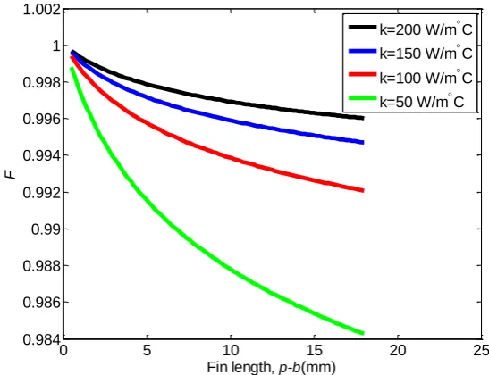
3.2.1 Fin efficiency (F) ... 36
3.2.2 Collector Efficiency Factor (F’)... 38
3.3 Thermal analysis in the flow (x) direction ... 40
3.3.1 Effects of design/operating parameters ... 47
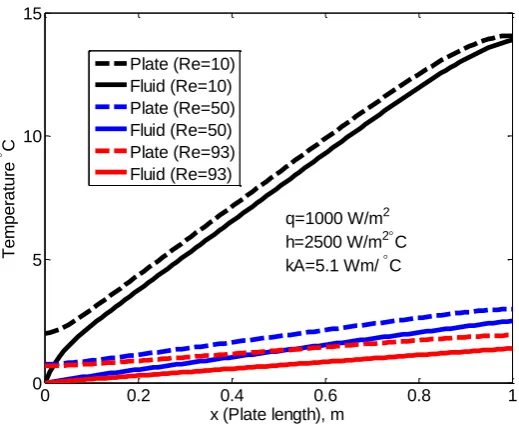
3.3.1.1 Flow rate ... 47
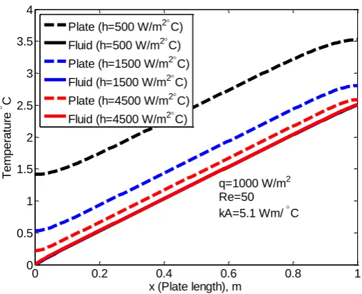
3.3.1.2 Heat Transfer coefficient ... 48
3.3.2 The Heat Removal Factor (FR) ... 52
3.3.3 The Flow Factor (F”) ... 54
3.4 Summary ... 55
4. Experimental Setup and Data Acquisition ... 57
4.1 Background ... 57
4.2 Heated Sandwich ... 58
4.2.1 Description ... 58
4.2.2 Design considerations ... 64
4.2.2.1 Clamping Force to withstand pressure of liquid ... 64
4.2.2.2 Deflection and thermal expansion of Slabs and Plates ... 66
4.2.2.3 Thermal Resistance at Plate – Top slab interface ... 67
4.2.2.4 Heat loss ... 70
4.2.2.5 Temperature differences ... 73
4.2.3 Data Reduction ... 74
4.2.3.1 Mean plate temperature ... 75
4.2.3.2 Mean fluid temperature ... 75
4.2.3.3 Heat flux ... 75
4.2.3.4 Surface Area ... 76
4.2.3.5 Heat transfer coefficient... 76
4.2.3.6 Pumping power per collector area ... 76
v
4.3 Counter Flow Heat Exchanger ... 77
4.3.1 Description ... 77
4.3.2 Data Reduction ... 81
4.3.2.1 Mean Slab temperature ... 81
4.3.2.2 Mean fluid temperature ... 82
4.3.2.3 Log mean Temperature difference ... 82
4.3.2.4 Heat flux ... 82
4.3.2.5 Surface Area ... 83
4.3.2.6 Heat transfer coefficient... 83
4.3.2.7 Pumping power per collector area ... 83
4.4 Measuring Instruments and Equipment ... 84
4.4.1 Thermocouples ... 84
4.4.1.1 Calibration ... 84
4.4.2 Resistance Temperature Detectors (RTDs) ... 86
4.4.3 Coriolis Mass Flowmeter ... 87
4.4.4 Differential pressure transducer ... 89
4.4.5 National Instrument data acquisition system ... 89
4.4.6 Circulating Bath ... 90
4.4.7 Statistical Analysis ... 91
4.4.8 Uncertainty ... 93
5. Numerical Analysis... 95
5.1 Background ... 95
5.2 ANSYS CFX - Overview and Validation ... 96
5.2.1 Heated Sandwich Validation ... 98
5.2.1.1 Geometry Creation ... 98
5.2.1.2 Mesh... 99
5.2.1.3 Domain and boundary conditions ... 102
5.2.1.4 Solution ... 106
5.2.1.5 Comparing numerical and experimental results ... 108
5.3 Summary ... 109
6. Results ... 110
6.1 Experimental results ... 110
6.1.1 Heated Sandwich ... 110
6.1.1.1 Aluminium Base ... 110
6.1.1.2 PTFE and Perspex slabs ... 113
6.1.2 Counter Flow heat exchanger ... 115
6.2 Numerical Results ... 118
6.2.1 Heated Sandwich Simulation ... 118
6.2.2 Simplified Model ... 121
6.3 Comparing Results ... 122
vii
6.3.2 Simulation and experimental results ... 124
6.3.3 Analytical and simulated results ... 125
6.4 Summary ... 126
7. Investigating Geometrical Parameters ... 127
7.1 Background ... 127
7.2 Aspect Ratio ... 127
7.2.1 Theory ... 128
7.2.2 Thermal Performance ... 130
7.2.3 Hydraulic Performance ... 134
7.2.4 Thermo-Hydraulic Performance ... 137
7.3 Surface Roughness ... 138
7.4 Manifold ... 142
7.5 Summary ... 146
8. Investigating Scaling Effects ... 147
8.1 Background ... 147
8.2 Entrance effects ... 147
8.3 Viscous dissipation ... 151
8.4 Conjugate Heat Transfer ... 153
8.5 Measurement uncertainties ... 161
8.6 Heat Transfer Correlation ... 164
9. Conclusion and Recommendations ... 168
9.1 Conclusion ... 168
9.2 Recommendations ... 172
ix
List of Tables
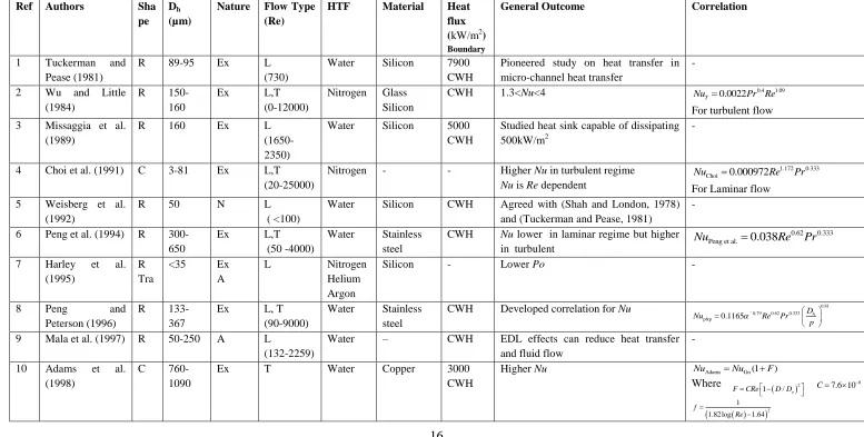
Table 2.1: Summary of previous studies ... 16
Table 4.1: Geometric parameters of the channels ... 62
Table 4.2: Deflection and expansion of slabs ... 66
Table 4.3: Thermal Resistance Details of Test rig Segments ... 69
Table 4.4: Statistical Analysis on thermocouple readings 3 10 , C ... 86
Table 4.5: Details of RTD signal converter module ... 87
Table 4.6: Details of circulating Bath ... 91
Table 4.7: Properties of Tyfocor ... 91
Table 4.8: Statistical parameters of measured instrument ... 92
Table 4.9: Uncertainties in measurement ... 94
Table 5.1: Details of the mesh used ... 101
Table 7.1: Geometric parameters of the channels ... 130
List of Figures
Figure 1.1: Schematic of micro-channel plate ... 7
Figure 3.1: Description of micro-channel plate directions ... 34
Figure 3.2: Micro-channel plate dimensions ... 35
Figure 3.3: Dimensions on a single micro-channel ... 36
Figure 3.4: Fin efficiency versus fin length ... 38
Figure 3.5: Collector efficiency factor versus heat transfer coefficient ... 39
Figure 3.6: (a) Elemental volume of plate ... 40
Figure 3.7: Temperature profile of fluid and metal plate at various flow rates ... 48
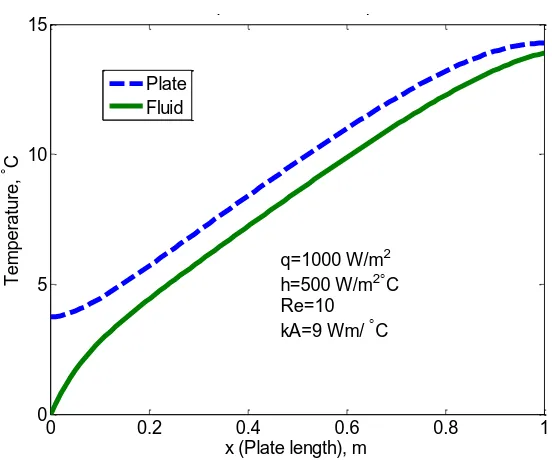
Figure 3.8: Temperature profile of fluid and metal plate at various heat transfer coefficients ... 49
Figure 3.9: Temperature profile of fluid and metal plate at various rates of axial thermal conductivity... 50
Figure 3.10: Temperature profile of fluid and metal plate for the upper extreme case ... 50
Figure 3.11: Temperature profile of fluid and metal plate for the lower extreme case ... 51
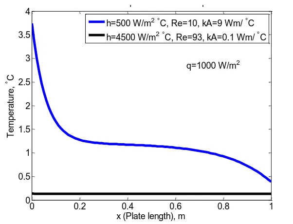
Figure 3.12: Temperature difference between plate and fluid (U) for the two extreme cases ... 52
Figure 3.13: Heat removal factor versus mass flow rate at different UL ... 53
Figure 3.14: Heat removal factor versus mass flow rate at different F' ... 54
Figure 3.15: Collector flow factor versus collector capacitance rate ... 55
Figure 4.1: Cross section of test rig through outlet port ... 58
Figure 4.2: Longitudinal 3D section of test rig ... 59
xi
Figure 4.4: (a) Inner face of Test Rig (b) Thermocouple arrangement on plate ... 61
Figure 4.5: Schematic showing thermocouple positions... 62
Figure 4.6 : Picture showing some of the plates ... 63
Figure 4.7: schematic of experimental setup... 63
Figure 4.8: Actual experimental setup ... 64
Figure 4.9: Isometric view of test rig showing fasteners ... 65
Figure 4.10: Engineering Drawing of the Test Rig ... 67
Figure 4.11: Schematic of thermal resistances in the test rig ... 68
Figure 4.12: (a) Distortion of grease layer (b) Procedure for measuring the sandwich ... 70
Figure 4.13: Heat loss at different (a) temperatures (b) input power ... 72
Figure 4.14: Temperature gradient across test rig ... 74
Figure 4.15: Cross section of counter flow heat exchanger ... 78
Figure 4.16: Inner faces of slabs ... 78
Figure 4.17: Thermocouple arrangement on slab ... 79
Figure 4.18: Schematic showing position of thermocouples ... 79
Figure 4.19: schematic of counter flow heat exchanger ... 80
Figure 4.20: The counter flow heat exchanger test rig (a) side view (b) end view .... 80
Figure 4.21: Micro – channel plate for counter – flow heat exchanger ... 81
Figure 4.22: (a) Thermocouples in bath (b) Calibration Kit ... 85
Figure 4.23: Thermocouple reading (a) before and (b) after calibration ... 86
Figure 4.24: RTD signal converter module ... 87
Figure 4.25: verifying accuracy of Coriolis mass flow meter ... 88
Figure 4.27: (a) Differential Pressure transducer (b) Pressure drop readings after
calibration ... 89
Figure 4.28: (a) SCXI-1102 Voltage input module (b) SCXI-1303 Terminal Block 90 Figure 5.1: (a) Heated sandwich geometry (b) Fluid domain ... 99
Figure 5.2: Temperature in flow direction at different number of nodes (a) Plate (b) Fluid ... 101
Figure 5.3: A magnified view of the mesh ... 101
Figure 5.4: The bottom slab domain ... 103
Figure 5.5: The fluid domain ... 105
Figure 5.6: The fluid-solid interface ... 106
Figure 5.7: Plate temperature at the plate fluid interface ... 108
Figure 5.8: Comparing experimental and numerical results ... 109
Figure 6.1: Measured temperature distribution in metal plate ... 110
Figure 6.2: Heat transfer coefficient versus fluid velocity ... 111
Figure 6.3: Nusselt number versus Peclet number ... 111
Figure 6.4: Pressure drop versus fluid velocity ... 112
Figure 6.5: Friction factor versus Reynolds number ... 113
Figure 6.6: Nusselt number versus Peclet number ... 113
Figure 6.7: Pressure drop versus fluid velocity ... 114
Figure 6.8: Friction factor versus Reynolds number ... 114
Figure 6.9: Temperature profile on slabs (a) Thin = 80°C (b) Thin =60°C ... 116
Figure 6.10: Heat transfer coefficient versus fluid velocity (a) Tyfocor (b) Water . 116 Figure 6.11: Nusselt number versus Reynolds number (a) Tyfocor (b) Water ... 116
Figure 6.12: Pressure drop versus fluid velocity (a) Tyfocor (b) Water ... 117
xiii
Figure 6.14: Plate temperature at the plate-fluid interface ... 118
Figure 6.15: Longitudinal fluid temperature profile for 3 channels... 119
Figure 6.16: Transverse fluid temperature profile at different lengths ... 119
Figure 6.17: Longitudinal velocity profile for 3 channels ... 120
Figure 6.18: Velocity contours at (a) Inlet manifold (b) Middle of channels (c) Outlet manifold ... 121
Figure 6.19: CFD geometry ... 122
Figure 6.20: Comparing analytic and experimental results (Re=10, Tin=20.5 °C) .. 123
Figure 6.21: Comparing analytic and experimental results (Re=54, Tin=59 °C) ... 123
Figure 6.22: Comparing analytic and experimental results (Re=100, Tin=40 °C) ... 124
Figure 6.23: Comparing experimental and simulated results... 125
Figure 6.24: Comparing analytical and simulated results ... 126
Figure 7.1: (a) H1 and H2 Nusselt numbers versus Aspect ratio (Shah and London, 1978, Dharaiya and Kandlikar, 2011) (b) Predicted heat transfer coefficient ... 130
Figure 7.2: (a) Heat transfer coefficient versus fluid velocity (b) Nusselt number versus Reynolds number ... 131
Figure 7.3: Comparing experimental results with theory (a) Tin = 5°C (b) Tin =20°C ... 133
Figure 7.4: Comparing results with correlations (a) Tin = 5°C (b) Tin = 20°C ... 134
Figure 7.5: (a) Pressure drop versus fluid velocity (b) Poiseuille number versus Reynolds number ... 135
Figure 7.6: (a) Friction factor versus Reynolds number (b) Pumping power versus fluid velocity ... 137
Figure 7.7 (a) Pump power vs Heat transfer coefficient ... 138
Figure 7.9: Surface finish on channel walls (a) Etched (b) Machined ... 139
Figure 7.10: Comparing machined and etched channels ... 141
Figure 7.11: Pressure drop and friction factor ... 141
Figure 7.12: Plate temperature at the plate fluid interface ... 143
Figure 7.13: Temperature profile transversely ... 143
Figure 7.14: Pressure distribution in the channels ... 144
Figure 7.15: Velocity distribution in channels ... 144
Figure 7.16: Mass flow rate in 3 channels ... 145
Figure 7.17: Temperature in manifold (a) inlet (b) outlet ... 145
Figure 8.1: Profile of ΔTpf along the plate (a)Tin= 5°C (b) Tin = 20°C ... 149
Figure 8.2: Local Nusselt number along the plate (a)Tin= 5°C (b) Tin = 20°C ... 149
Figure 8.3: Nusselt number vs Graetz number at various fluid temperatures ... 150
Figure 8.4: Transverse velocity profile at (a) entry (b) exit ... 151
Figure 8.5: Horizontal velocity profile at different locations ... 151
Figure 8.6: Brinkman number vs Nusselt number at various fluid temperatures .... 153
Figure 8.7: Nusselt number vs axial conduction number ... 155
Figure 8.8: Profile of ΔTpf at two extreme cases ... 156
Figure 8.9: Nusselt number vs axial conduction number in Counter flow heat exchanger ... 157
Figure 8.10: Simulated fluid and plate temperature profile ... 158
Figure 8.11: Temperature profile at channel walls ... 159
Figure 8.12: Heat flux profile at channel walls. ... 160
Figure 8.13: Comparing analytical and simulated results ... 161
Figure 8.14: Corrected Nusselt numbers versus Peclet numbers ... 162
xv
Figure 8.16: Corrected Nusselt number vs axial conduction number ... 163
Figure 8.17: Friction factor versus Reynolds number ... 164
Figure 8.18: Heat transfer Coefficient versus Peclet number ... 164
Acknowledgements
I would like to express my sincere gratitude to my supervisor, Dr Stan Shire, for his
continuous support, inspiration and the immense knowledge imparted throughout my
PhD study - I could not have asked for anyone better. My deep appreciation also
goes to Dr Roger Moss for his help, advice and critique. Also, to all members of staff
of the Sustainable Thermal Energy Technology Research Group for the invaluable
insight and help in designing and troubleshooting experiments; Prof Bob Critoph, Dr
Zacharie Tamainot-Telto, Dr Roger Thorpe and Dr Steve Metcalf. Special thanks to
Dr Layi Alatise for his advice and motivation. A big thank you to the technicians, for
fabricating various test rigs.
I am greatly indebted to my family; my Parents for the huge financial
sacrifice/investment made towards this degree, words cannot express my gratitude.
Dr Arinola Adefila, for her immense contribution – it is very much appreciated.
Other family members and friends, too numerous to mention, I am deeply grateful.
To my darling wife, Dami - Adeemama, thank you for your understanding, patience,
support and inspiration. You are simply the best. Above all, I am grateful to God
xvii
Declaration
I declare that the work in this thesis has been composed by me and no portion of the
work has been submitted in support of an application for another degree or
qualification of this or any other university or other institute of learning. The work
has been my own except where indicated and all quotations have been distinguished
by quotations marks and the sources of information have been acknowledged.
Parts of this thesis have been published by the author. These publications are listed
Contributions to Knowledge
Peer Reviewed Journal Papers
1. Oyinlola, M.A., Shire, G.S.F. and Moss, R. W. (2015) "Thermal analysis of a
solar collector absorber plate with microchannels," Experimental Thermal
and Fluid Science,67, 102-109.
2. Oyinlola, M.A., Shire, G.S.F. and Moss, R. W. (2015) "Investigating the
Effects of Geometry in Solar Thermal Absorber Plates with Micro-Channels"
International journal of heat and mass transfer, 90, 552-560.
3. Oyinlola, M.A., Shire, G.S.F. and Moss, R. W. (2015) "The Significance of
Scaling Effects in a Solar Absorber Plate with Micro-Channels" Applied
Thermal Engineering, 90, 499-508
Peer Reviewed conference proceedings.
1. Oyinlola, M.A. and Shire, G.S.F. (2013) Investigating Heat transfer in
Absorber plates with mini channels, The 13th UK Heat Transfer Conference
(UKHTC), London, UK.
2. Oyinlola, M.A., Shire, G.S.F. and Moss, R. W. (2014) Analysis of
temperature distribution in absorber plates with microchannels. The 5th
international conference on Heat Transfer and Fluid Flow in Microscale
(HTFFM V) , Marseille, France.
3. Oyinlola , M.A., Shire, G.S.F. , Moss, R. W. and Khaliji Oskouei, M (2014)
Investigating the effects of channel aspect ratio on fluid flow and heat
transfer in absorber plates with minichannels The 10th International
Conference on Heat Transfer, Fluid Mechanics and Thermodynamics
xix
Accepted conference papers and posters(unpublished)
1. Oyinlola , M.A. and Shire, G.S.F. (2013) Optimising heat transfer and fluid
flow in compact solar collectors, UK Energy Research Centre ( UKERC)
PhD summer school, Coventry, UK [Poster presentation]
2. Oyinlola, M.A., Shire, G.S.F. and Moss, R. W. (2014) Investigating heat
transfer in compact absorber plates manufactured by different techniques.
The 15th International Heat Transfer Conference (IHTC15), Kyoto, Japan.
Abstract
Analytical, computational and experimental studies were carried out to investigate heat transfer and fluid flow in micro-channel absorber plates for compact (thin and light-weight) solar thermal collectors. The main objective of the work was to study different design and/or operating scenarios as well as study the significance of various micro-scaling effects.
Analytical investigation showed that, under similar conditions, the proposed design yields a much higher fin efficiency, F and collector efficiency factor, F’ compared with the conventional solar collector design. An analytical model combining convective heat transfer in the collector fluid with axial conduction in the metal plate was developed. The predicted plate temperature profiles from the analytical model were in close agreement with the measured profiles. The model further showed that axial thermal conduction can significantly alter the plate temperature profile.
Experiments were designed to represent real life operation of the proposed system. A CFD study, using the same design and operating parameters, produced results comparable with experiments. This numerical simulation also gave further insight into the heat transfer and fluid flow patterns in the micro-channel plate.
The effect of channel cross section geometry was studied. The Nusselt number was observed to increase as the aspect ratio approached unity. Measured friction factors were similar in trend to the predictions for rectangular channels, although the overall rise in fluid temperature resulted in slightly lower friction factors. Thermal performance reduced slightly with increase in hydraulic diameter.
The significance of various scaling effects was also investigated experimentally and numerically. Most of the typical scaling effects such as viscous dissipation and entrance effects were found to be insignificant however, conjugate heat transfer, surface boundary condition, surface finish and measurement uncertainties could be significant. The results showed a Reynolds number dependent Nusselt number which has been attributed to axial thermal conduction.
It was also observed that only three walls were transferring heat; the walls of heat transfer had a uniform peripheral temperature while the heat flux varied peripherally. The closest simplified thermal boundary condition to represent heat transfer in these channels is the H1 with three (3) walls transferring heat. Increased surface roughness (obtained by using an etching technique to create the channels) was found to have a detrimental effect on heat transfer.
xxi
Nomenclature
a Channel depth (m)
A Longitudinal cross sectional area (m2)
AC Collector Area (m2)
Ap Plate area (m2)
AL Longitudinal cross sectional area of plate (m2)
b Channel width (m)
Br Brinkman number
2
m L
v Br
q
(-)
CCR Collector capacitance rate (-)
Ci constant (-)
cp Specific heat capacity (J/kg °C)
Dh Hydraulic diameter (m)
E Young’s modulus of elasticity (Pa)
e electron charge (C)
F Fin Efficiency (-)
f Friction factor (-)
F’ Collector Efficiency Factor (-)
F” FR/F’ (-)
Ff Force exerted by fluid (N)
FR Heat Removal Factor (-)
g Acceleration due to Earth's gravity (m/s2)
Gz Graetz Number
h
RePrD Gz
L
(-)
h Heat transfer coefficient (W/m2 °C)
H Overall heat transfer coefficient (W/m2 °C)
i Subscript number (-)
Ƙ Debye-Huckel parameter (1/m)
k Thermal conductivity (W/m °C)
kb Boltzman constant (1/m)
kf Thermal conductivity of fluid (W/m °C)
kp Thermal conductivity of metal (W/m °C)
L Length of channel (m)
Lhyd hydrodynamic entry length (m)
Lt Thermal entry length (m)
Ly Plate width (m)
M Axial conduction number (-)
m
Mass flow rate (kg/s)n number of observations (-)
n0 Ionic number concentration (1/m3)
Nc Number of channels in plate (-)
Nu Nusselt number h
f
hD Nu
k
(-)
p Channel pitch (m)
P Width of plate (m)
Pe Peclet number
Pe
RePr
(-)Pf Pressure exerted by fluid (Pa)
Po Poiseuille number Po fRe (-)
Pr Prandtl number p
f c Pr
k
xxiii
q Heat flux density (W/m2)
qc Heat flux density from channel walls (W/m2)
Q Rate of Heat Transfer (W)
qL Heat flux per unit Length (W/m)
qt Heat flux on top of plate (W/m2)
R Thermal Resistance (W/m °C)
Ra Mean deviation for surface roughness (µm)
Rp Maximum peak height (µm)
Rq Root mean squared (µm)
Rt Maximum height of profile (µm)
Re Reynolds number vDh
Re
(-)
s Surface area per unit length of channel (m)
S Surface area per unit length of plate (m)
Sc Total surface area of channels (m2)
SE Viscous work (J)
SM External momentum sources (J)
SF Shape factor (m)
t Students t’s parameter (-)
T Temperature (°C)
Ta Ambient Temperature (°C)
Tb Base Temperature (°C)
Tf Average fluid temperature (°C)
Tin Fluid temperature at inlet (°C)
Tout Fluid temperature at outlet (°C)
U Plate-Fluid Temperature difference (Local) (°C)
UL Overall Plate heat loss coefficient (W/m2 °C)
UE Internal Energy (J)
V Voltage drop (V)
vm Mean fluid velocity (m/s)
w
Pumping power (W/m2)x Position in flow direction (m)
xi Observation i (-)
y Position in transverse direction (m)
z valence of the positive/negative ions (-)
α Aspect ratio (-)
αTE
Coefficient of Thermal linear expansion (1/°C)β volumetric thermal expansion coefficient (1/°C)
δ Plate thickness (m)
Δ95 95% confidence level (-)
Δp Pressure drop (Pa)
ΔTpf Plate-fluid temperature difference (average) (°C)
ε Relative permittivity of the medium (-)
ε0 Permittivity of vacuum (F/m)
θ(x) local fluid Temperature (°C)
ν Kinematic viscosity (m2/s)
ρ Density (kg/m3)
σ Standard deviation (-)
σ2
Variance (-)
xxv
µ Dynamic Viscosity (Pa.s)
ώ uncertainty (-)
Glossary
A Analytical
BIPV Building Integrated Photovoltaic
C Circular
CEL CFX Expression Language
CFD Computational Fluid Dynamics
CFPC Compact Flat Plate Collector
CFPC Compact Flat Plate Collector
cs Cold Slab
CWH Constant Wall Heat Flux
CWT Constant Wall Temperature
DAQ Data Aquisistion
EDL Electric double layer
EFPC Evacuated Flat Plate Solar Collector
Ex Experimental
FPC Flat Plate Collector
GHG Greenhouse Gas Emissions
H1 Axially CWH and circumferentially CWT.
H2 Uniform wall heat flux, axially, and circumferentially
hf Hot fluid
hfin Hot fluid at inlet
hfout Hot fluid at outlet
HTC Heat Transfer Coefficient
L Laminar
xxvii
MEPCM microencapsulated phase change material
N Numerical
PV Photovoltaic
R Rectangle
RTD Resistance temperature detector
Sh hot slab
T Turbulent
Th Theoretical
Tra Trapezium
Tri Triangle
1. Introduction
1.1Background
Energy is a vital element in any society; it improves opportunities for access to basic
amenities and life’s necessities such as water, food and clothing. Sadly, it is common
knowledge that more than two billion of the world’s population (the majority of
whom live in rural areas) have no access to efficient energy supply. Technological
and economic advancement have also resulted in additional drains on current energy
supplies. On the other hand, environmental concerns, rising energy prices as well as
government incentives are creating opportunities for renewable sources to meet the
growing energy demand.
Buildings account for the bulk of the energy demand (Eicker, 2003); according to the
United Nations Environment Programme (UNEP) “Buildings use about 40% of
global energy ... Yet, buildings also offer the greatest potential for achieving
significant GHG emission reductions, at least cost, in developed and developing
countries” (UNEP, 2014). These highlight the need for more research and
development on technologies that promote the uptake of renewable energy in
buildings. Current renewable systems used in buildings include conventional
photovoltaic (PV) arrays, building integrated PV (BIPV), biomass systems,
evacuated tube collectors and flat plate solar collectors (FPC). This research focuses
on the absorber plate of a novel FPC design which presents opportunities for
building integration.
1.1.1 Flat Plate Collectors
FPCs are the most used solar collecting devices (Kalogirou, 2003). In their standard
2
and well insulated sides and bottom; a working fluid flows below or on top of the
absorber. Solar radiation passes through the transparent cover to the absorber plate
which absorbs and transfers the bulk of the energy to the working fluid. Standard
FPCs are cost-efficient, robust and effective even with diffuse solar irradiation. FPCs
are typically permanently fixed in position and require no tracking of the sun, they
are usually oriented directly towards the equator, facing south in the northern
hemisphere and north in the southern. In the last century, the use of these systems
has evolved from primitive uses such as drying agricultural products, to more
advanced uses such as producing steam and process heat. These improvements are
results of the numerous studies done to improve energy gain and reduce thermal
losses. A summary of the various approaches undertaken are grouped and discussed
below.
1.1.1.1Geometry
Performance enhancements have been achieved by innovatively manipulating the
geometry; a detailed energy and exergy analysis was done by Farahat et al. (2009)
who varied different geometrical parameters while a review of different artificial
roughness elements used to enhance the heat transfer coefficient was presented by
Kumar et al. (2012). Kundu (2002) did a detailed comparative study on absorber
plates of different geometry and the effect of plate aspect ratio was theoretically
studied by Yeh et al. (2003). Badescu (2006) and Tiris et al. (1995) are some who
have investigated optimising fin geometry. Also, the effect of spacing between riser
tubes has been studied by many including Bello and Sambo (1992) and Ghamari
Innovative ways of improving the heat transferred to the working fluid have been
proposed; Matrawy and Farkas (1997) compared parallel and serpentine tube
arrangements in conventional sheet and tube absorber plates, Rommel and Moock
(1997) analytically studied absorber plates with rectangular fluid ducts and Alvarez
et al. (2010) investigated absorber plates having surface contact with the working
fluid. Dović and Andrassy (2012) proposed two designs of collector without tubes,
parallel flat and corrugated absorber plates of chevron type, as a method of
improving performance. Del Col et al. (2013) found FPCs with roll-bond absorber
plates (channels for the liquid are integrated in the absorber plates) to provide
higher performance compared with conventional FPCs. Shariah et al. (1999)
numerically investigated the effect of thermal conductivity of the absorber plate on
the overall performance.
1.1.1.2 Working Fluid
The working fluid plays an important role in the performance of FPCs. various
approaches have been adopted in maximising performance with emphasis on the
working fluid. Chun et al. (2009) studied the effect of the working fluid on the
performance of solar energy systems in buildings while Rayegan and Tao (2011) did
a comprehensive study on working fluids and proposed a procedure for the selection
of working fluids for solar organic Rankine cycles (ORC). They suggested 11 fluids
for use in solar ORCs based on the category of solar collectors. Similar to this, is the
work of Tchanche et al. (2009), who performed a study on fluid selection for a low
temperature Solar ORC. The use of nano – fluids in FPCs has been proposed by
4
Phase change in flows has also been used to improve performance, for example
Ordaz-Flores et al. (2012) used acetone and methanol as working fluids for a two
phase flat plate solar system. Comparisons with the conventional systems showed
that the phase change systems exhibits slightly lower performance, however, they
offer advantages of no freezing, corrosion, scaling, fouling, nor blocking of the
tubing, that improve the lifetime of the system.
Similar to this is the integration of heat pipes where the absorber is the evaporator.
Azad (2012) performed a comparative study on 3 different types of heat pipe solar
collectors and concluded that they all performed satisfactorily. Other researchers
who have studied heat pipe solar collectors include Mathioulakis and Belessiotis
(2002), Tanak et al. (2005), Hussein et al. (2006) and Zhao et al. (2010).
1.1.1.3Minimising losses
Evacuated solar collectors utilise the technology of vacuum insulation in eliminating
convection losses and also have the potential of supressing gas conduction
(depending on the pressure). This is the crux of evacuated tube solar collectors, and
application of vacuum glazing to FPCs is increasingly becoming popular. Eaton and
Blum (1975) studied the effect of evacuating FPCs, they found that at a pressure of
1–25 torr (100-3000 Pa), natural convection heat loss from the absorber was
eliminated for absorber-to-cover spacing’s up to 15 cm. They noted that absorbers
with selective surfaces had a more reduced heat loss, however, upward losses from
collector were as a result of gas conduction. Beikircher et al. (1995) studied the gas
heat conduction in an evacuated flat plate collector (EFPC) for a pressure range of
10-3 to 104 Pa. They reported that at 0.1Pa, heat conduction in air was completely
their study, investigated the effects of filling the envelope with other gasses on
thermal losses. They noted that the reduction of the gas heat conduction with
comparison to air is 32% for argon, 40% for SF6, 62% for krypton and even 77% for
xenon. However, based on an economic and technical analysis, they suggested that
Krypton was the best suited gas for filling. Vestlund et al. (2012) and Vestlund et al.
(2009) studied the thermal and mechanical performance of filling the collector with
an inert gas at normal pressures. Their results show that this could reduce overall
heat losses by up to 20%.
Absorber plates with selective surfaces, commonly called selective absorbers, have
been researched and developed to further improve collector performance. Selective
surfaces have high absorptance for the solar spectrum range (0.2-2.5 µm) thereby
maximising the absorbed solar energy. They also have a low emittance for higher
spectrum range ( >2.0 µm) therefore losses are minimised. Some of the studies on
selective surfaces include Correa et al. (2014), Davoine et al. (2013) and Tharamani
and Mayanna (2007). The use of anti-reflective coatings is another method that has
been adopted to minimise losses. Some scholars who have studied this approach
include Chen et al. (2011), Nielsen et al. (2014) and Barshilia et al. (2012).
Aerogels have been used as a transparent insulation to minimise heat loss.
Researchers who have studied these include Dowson et al. (2012), Svendsen (1992)
and Nordgaard and Beckman (1992) .
1.1.1.4Building Integration
Developers have for long been working towards the integration of FPCs into
6
architectural designs, Tripanagnostopoulos et al. (2000) investigated FPCs with
coloured (black, blue and red brown) absorbers; they recorded high thermal losses in
the unglazed collectors but used flat booster reflectors to increase the radiation
falling on the collectors. Juanicó (2008) presented a new design of a roof-integrated
water solar collector. Matuska and Sourek (2006) compared the thermal behaviour of
façade collectors with standard roof mounted collectors and concluded that façade
collectors should have approximately 30% greater area than similar standard FPC in
order to have comparable performance. They noted that façade collectors also affect
the indoor comfort of buildings by limiting the increase in temperature to no more
than 1 °C in all their investigated configurations. A low cost solar water heating
system using cement concrete was studied by Chaurasia (2000); the system produced
water which varied from 36 °C to 58 °C. A comprehensive review of various
approaches to building integration of solar systems is presented by Hestnes (1999).
1.1.2 Compact Flat Plate Collectors – The game changer
At present, The University of Warwick, together with Loughborough University and
University of Ulster are developing a compact (thin and light-weight) evacuated flat
plate collector (CFPC) which combines the benefits of evacuated tube collectors
with that of flat plate collectors. This collector design will be an architecturally
attractive option for incorporation in buildings as an alternative to conventional flat
panel or evacuated tube collectors. It will also be a landmark achievement in
building integrated FPCs.
This thesis presents research focused on investigating the thermal and hydraulic
performance of the absorber plates for this collector design. The proposed absorber
mm) replace the conventional FPC arrangement of tubes bonded to a metal sheet. A
schematic of the micro-channel plate is shown in Figure 1.1. In addition to
achieving the compact size, plates of this design offer the added advantage of
enhanced convective heat transfer (based on the premise that the heat transfer
coefficient is inversely proportional to the channel’s hydraulic diameter), uniform
temperature distribution in the transverse direction and eliminates the bond
resistance between the tubes and sheet in conventional FPC design.
Figure 1.1: Schematic of micro-channel plate
As can be observed from the brief overview of studies focused on FPCs presented,
the majority of the studies on FPC absorber plates have focused on conventional
collector design with tubes bonded to a sheet. Currently, there is limited published
work on the micro-channel absorber plate design. Some of the few researchers who
have published work on application of micro-channels in solar collectors include
Khamis Mansour (2013); who looked at flat plate rectangular channelled absorber
plate, Sharma and Diaz (2011) who investigated mini-channel application in
evacuated tubes and Deng et al. (2013) who studied a novel FPC with
micro-channel heat pipe array.
Though heat transfer and fluid flow in micro-channels has been extensively studied
8
components. Also, a wide dispersion in the results obtained in this field can be
observed from the literature, which has been attributed to scaling effects. An
additional peculiarity of this design is the thermal boundary condition that will exist
on the channel walls. Therefore, a detailed study is required to understand the
thermal and hydraulic behaviour of these channels.
1.2Aim and Objectives
The aim of the current research is to investigate and optimise the performance of the
absorber plates for the proposed compact flat plate collector. Accurately
understanding the thermal and hydraulic behaviour has implications for the design
and operation of the proposed system. The main objectives of the current research
can be summarised as follows
To compare performance of this design to predictions of conventional theory.
To study the significance of the various scaling effects on the absorber plate
performance.
To study the effects of channel design on performance.
To propose optimal channel design and corresponding operating condition
for this system.
To propose accurate methods of predicting collector performance.
To achieve these, analytical, experimental, and numerical analyses were carried out
to investigate the heat transfer and fluid flow in plates of this design.
1.3Summary of the Thesis
Chapter 1 presents a background to the research as well as highlights the evolution
Chapter 2 presents a review of literature on heat transfer and fluid flow in
micro-channels. It reviews previous experimental and numerical studies on heat transfer
and fluid flow in micro-channels. This chapter compares and contrasts the different
methods and results obtained by several researchers.
Chapter 3 is an analytical study into the thermal and hydraulic performance of the
proposed plate design. Analytical models for predicting fluid and plate temperature
are derived here as well as parameters typically used for characterising FPCs such as
fin efficiency (F), collector efficiency factor (F’), heat removal factor (FR) and flow
factor (F”). The chapter further uses the analytical models to investigate the effects
of varying design and operating parameters.
Chapter 4 describes how experiments were designed to measure the quantities
needed for estimating performance. It gives a detailed explanation of the
experimental facility used for all laboratory tests as well as discusses the various
components of the experimental apparatus, how they were calibrated and the various
design considerations. This chapter also presents details of data analysis including
the dimensionless parameters.
Chapter 5 presents details of the numerical studies done using the commercial CFD
package Ansys CFX. The governing equations, physics definition, geometry, mesh,
boundary conditions etc. are discussed in this chapter. It also presents results on the
validation of the software.
Chapter 6 presents and compares the results obtained from the analytical,
10
Chapter 7 draws from the numerical and experimental studies to investigate the
effect of the channel geometry on the thermal and hydraulic performance of the
absorber plate. The design parameters varied in this study include the channels’
aspect ratio, depth, width, pitch, length and surface finish of channel walls. The main
operating parameter varied here is the mass flow rate. To study these effects over a
range of thermo-physical properties, two (2) heat transfer fluids were used at
temperatures ranging from 5°C – 60°C.
Chapter 8 uses the results from the experimental and numerical studies to investigate
the micro-scaling effects on the thermal and hydraulic performance of the plates.
These scaling effects include entrance effects, conjugate heat transfer and viscous
dissipation.
Chapter 9 presents the main conclusions of this work. It also recommends further
2. Literature Review
2.1Background
Heat transfer and fluid flow in miniaturized (micro or mini) channels has been the
focus of many researchers since Tuckerman and Pease (1981) pioneered the study of
heat transfer in micro-channels over three decades ago. These studies were largely
in the context of micro-electronic components. In recent times however, due to
advantages of compact size and high heat sinking capabilities, the use of
miniaturized channels as heat sinks/ heat exchangers has been extended to other
fields such as automotive, chemical and food industries, environmental technology
and the aviation and space industries (Schubert et al., 2001). The definition by
Kandlikar and Grande (2003) which defines conventional channels as those having
hydraulic diameters above 3 mm is adopted in this study.
The theory and correlations of heat transfer and fluid flow in conventional sized
channels are well established; constant Nusselt number in the range 0.457 – 8.235,
with the exact value depending on boundary conditions and geometry, are expected
for fully developed laminar flow (Shah and London, 1978, Holman, 2010,
Wibulswas, 1966). Similarly in terms of friction factor, constant Poiseuille numbers
in the range 56.92 – 96.00 are expected. The results from the extensive studies on
heat transfer in miniaturized channels are still inconsistent. Reviews on experimental
and numerical studies of heat transfer in micro-channels published by Dixit and
Ghosh (2015), Asadi et al. (2014), Rosa et al. (2009), Mokrani et al. (2009), Hetsroni
et al. (2005b), and Sobhan and Garimella (2001) confirm the very large scatter in
published results. These reviews unanimously attribute the dispersion to “scaling
effects”, which result from neglecting phenomena that are insignificant in
12
of these scaling effects include surface roughness (Qu et al., 2000), entrance and exit
effects (Lee et al., 2005, Rahimi and Mehryar, 2012), conjugate heat transfer
(Maranzana et al., 2004, Gamrat et al., 2005), thermal boundary conditions
(Dharaiya and Kandlikar, 2011), viscous dissipation (Morini, 2005), electric double
layer (Mala et al., 1997) and increased measurement uncertainties (Morini, 2004). It
should be noted that the constant Nusselt and Poiseuille number solutions are
obtained under some assumptions including
I. Steady fully developed flow.
II. The thermo-physical properties of the fluid do not vary with the temperature.
III. The fluid can be treated as a continuum medium.
IV. Incompressible flow.
V. Idealised boundary conditions (constant wall temperature or constant wall
heat flux).
VI. The heating due to viscous dissipation can be neglected.
VII. Surface roughness has negligible effects in laminar flow.
Some of these assumptions are not valid at the micro scale level; this explains the
need to better understand the scaling effects. The design and operating conditions of
the flow channels can increase the influence of these scaling effects on overall
performance. Therefore, in order to optimise design and operation, it is necessary to
investigate the heat transfer and fluid flow in this design of absorber plates. This
chapter reviews previous studies on heat transfer and fluid flow in miniaturised
2.2Overview
Table 2.1 presents a summary of the research conducted in this field from 1981 to
2014. The geometry of channels studied, nature of study and a summary of their
results (relevant to this study) is presented. It can be observed that most of the
studies conducted between 1981 and 1999 were experimental or analytical while
more numerical simulations were conducted after 2000. It can also be observed that
various geometries (circular, rectangular, triangular, and trapezoidal), materials
(copper, aluminium, and silicon) and heat transfer fluids (water, refrigerants, air,
nano-fluids) have been used. These have all been done to improve performance of
micro-channel heat sinks. For example, different geometries have been used to
increase the area available for heat transfer and high thermal conductivity materials
have been used to improve heat sinking performance.
Table 2.1 shows that some studies have reported lower Nusselt numbers compared
with predictions for conventional sized channels. These include Choi et al. (1991),
Peng et al. (1994), Peng and Peterson (1996) and (Dixit and Ghosh, 2013). Most of
these studies have found the low Nusselt numbers to be Reynolds number dependent
unlike conventional channels where Nusselt number is constant for fully developed
flow. In fact, Nusselt number correlations for micro-channels, which are Reynolds
number dependent, have been proposed by Choi et al. (1991), Peng et al. (1994)
and Peng and Peterson (1996). Qu et al. (2000) reported lower Nusselt numbers
(1<Nu<2) from their experimental study, however, their Nusselt numbers were Re
-independent. Gamrat et al. (2005) found a significant reduction in Nusselt number
when the hydraulic diameter was less than 1 mm. Celata et al. (2006) observed lower
Nusselt numbers than the theoretical value of 4.364 especially for flows at low
14
numbers flow in mini-channels. They observed a linear variation of Nusselt number
with the Reynolds number and found it to closely match the prediction of Choi et al.
(1991). Others who have acknowledged low Nusselt numbers in their study include
Nonino et al. (2009) and Rahimi and Mehryar (2012).
Some researchers have observed higher Nusselt numbers, both in the laminar and
turbulent regime, compared with conventional theory. Wu and Little (1984) found
their experimentally measured Nusselt number to be higher than those for
conventional channels. A similar observation was made by Adams et al. (1998) who
performed experiments on single phase turbulent flow. Yu et al. (1995), Celata et al.
(2002) and Bucci et al. (2003) have also found the Nusselt number to exceed the
theoretical predictions for conventional channels.
Lee et al. (2005) found that that their experimental results disagreed with all of the
tested correlations but were well predicted by numerical simulations. This is because
the boundary conditions did not fit the requirements of correlations. They
recommended the use of numerical simulations with suitable boundary conditions,
instead of correlations, to predict the performance of heat sinks using microchannels.
Gamrat et al. (2005) observed experimental Nusselt numbers that were about 60%
less than the conventional value, however, their numerical results agreed with theory.
The friction coefficient was found to decrease drastically at low Reynolds number
by Toh et al. (2002). This was attributed to high fluid temperature which yielded
low viscosity.
Some studies have suggested that conventional predictions can accurately predict
heat transfer and fluid flow in micro-channels. Weisberg et al. (1992) performed a
error) well with the experimental results of Tuckerman (1984). Harms et al. (1999)
found the Nusselt number to be similar to conventional correlations. The slight
deviation in Nusselt number at low Reynolds number observed in their experimental
results was attributed to measurement errors. Qu and Mudawar (2002) numerically
and experimentally studied laminar flow in micro-channels and found their results to
agree well with theory. The experimental study by Owhaib and Palm (2004) found
the heat transfer results to be accurately predicted by conventional correlations. Lee
and Garimella (2006) numerically investigated heat transfer in thermally developing
flow in rectangular micro-channels of different aspect ratios under H1 (axially
constant wall heat flux and circumferentially constant wall temperature) thermal
boundary condition. Their proposed correlation was in good agreement with
conventional theory. Similarly, Dharaiya and Kandlikar (2011) numerically
investigated heat transfer in rectangular micro-channels under H2 (uniform wall heat
flux, axially and circumferentially) boundary condition. They proposed Nusselt
number correlations which agreed with conventional theory. Toh et al. (2002) also
compared the results of their 3D numerical simulation with the experimental results
of Tuckerman (1984) and found good agreement. Qu and Mudawar (2002) , Lelea et
al. (2004) and Tiselj et al. (2004) performed experimental and numerical studies, in
each case both studies agreed with conventional theory.
From the brief overview presented above as well as the summary presented in Table
2.1, it is clear that existing correlations can not be used to adequately describe the
heat transfer in miniaturised channels. The significance of the various scaling effects
16 Table 2.1: Summary of previous studies
Ref Authors Sha
pe Dh (µm)
Nature Flow Type (Re)
HTF Material Heat
flux (kW/m2)
Boundary
General Outcome Correlation
1 Tuckerman and
Pease (1981)
R 89-95 Ex L
(730)
Water Silicon 7900
CWH
Pioneered study on heat transfer in micro-channel heat transfer
-
2 Wu and Little
(1984)
R
150-160
Ex L,T
(0-12000)
Nitrogen Glass
Silicon
CWH 1.3<Nu<4 0.4 1.09
0.0022
T
Nu Pr Re
For turbulent flow
3 Missaggia et al.
(1989)
R 160 Ex L
(1650-2350)
Water Silicon 5000
CWH
Studied heat sink capable of dissipating
500kW/m2
-
4 Choi et al. (1991) C 3-81 Ex L,T
(20-25000)
Nitrogen - - Higher Nu in turbulent regime
Nu is Re dependent
1.172 0.333
Choi 0.000972
Nu Re Pr
For Laminar flow
5 Weisberg et al.
(1992)
R 50 N L
( <100)
Water Silicon CWH Agreed with (Shah and London, 1978)
and (Tuckerman and Pease, 1981)
-
6 Peng et al. (1994) R
300-650
Ex L,T
(50 -4000)
Water Stainless
steel
CWH Nu lower in laminar regime but higher
in turbulent
0.62 0.333 Peng et al. 0.038
Nu Re Pr
7 Harley et al.
(1995)
R Tra
<35 Ex
A
L Nitrogen
Helium Argon
Silicon - Lower Po -
8 Peng and
Peterson (1996)
R
133-367
Ex L, T
(90-9000)
Water Stainless
steel
CWH Developed correlation for Nu 0.81
0.79 0.62 0.333 p&p 0.1165
h D
Nu Re Pr
p
9 Mala et al. (1997) R 50-250 A L
(132-2259)
Water – CWH EDL effects can reduce heat transfer
and fluid flow
-
10 Adams et al.
(1998)
C
760-1090
Ex T Water Copper 3000
CWH
Higher Nu NuAdamsNuGn(1F)
Where 2
1 / o
FCRe D D
6 7.6 10
C
2
1 1.82 log 1.64 f
Re
11 Tso and Mahulikar (1998)
R - A L,T Water – - Br explains deviation -
12 Harms et al.
(1999)
R Tra
400-1900
Ex L ,T
(173-12900)
Deionize d water
Silicon - slight Nu deviation at low Re, attributed
to measurement errors
-
13 Peterson (1999) C 0.2 N L Air - Conduction in micro-channel materials
can reduce performance
-
14 Kim and Kim
(1999)
R 0.1 A L
(730-836)
Water Silicon CWH Identified aspect ratio and the effective
thermal conductivity ratio as variables of engineering importance
-
15 Ravigururajan
and Drost (1999)
Ex L
(220-1250)
R124 30-90
CWH
h is 2-8 times higher
Pressure drop is 8-17 times higher
-
16 Mala and Li
(1999)
R 50-250 A L
(132-2259)
Water - CWH Po increases with Re. -
17 Rahman (2000) R
300-600
Ex L,T Water Silicon 100
CWH
Nu is Re dependent -
18 Fedorov and
Viskanta (2000)
R <100 N L Water Silicon 1000
CWH
combined convection–conduction heat transfer produces very complex three-dimensional heat flow patterns
-
19 Qu et al. (2000) Tra 62-169 Ex L Deionize
d Water
Silicon CWH Experimental Nu is 2- 3 times lower
than CFD prediction’ attributed to Surface roughness
Rm
Qu theory
Rmw
Nu Nu
20 Tunc and
Bayazitoglu (2001)
C - N L - - CWH
CWT
Nu increases with Pr and reduces with
Kn
-
21 Choi and Cho
(2001)
R
6900-25000
Ex L,T
(3000-15000) Paraffin Water Copper Silicon 100-400 CWH
Enhancement factor (h/ΔP) at low
aspect ratio but begins to decrease above aspect ratio of 0.2
-
22 Tunc and
Bayazitoglu (2002)
R - N L,T – – CWH
(H2)
Nu increases as aspect ratio approaches
unity
18
23 Qu and Mudawar
(2002)
R 350 Ex
N L (139-1672) Deionize d water Oxygen free copper 1000-2000 CWH
Agreed well with CFD prediction
Re dependent Pressure drop attributed
to temperature dependent fluid
properties
-
24 Ryu et al. (2002) R <100 N L
(364)
Water Silicon 1000
CWH
Channel geometry (width) crucial in dictating the performance of a micro-channel heat sink.
-
25 Zhao and Lu
(2002)
R A
N
L Water Copper
Silicon
CWH CWT
Nu increases as α is increased and
decreases with increasing k̃
-
26 Gao et al. (2002) R
200-2000
Ex L,T
(40-10000)
Deminer alised water
Brass 500
CWH
Nu decreases more at lower depths
Nu 60% less than conventional value
Conventional laminar Po obtained
27 Hegab et al.
(2002)
R
100-200
Ex T R134a Aluminium CWH Nu and f are lower
28 Toh et al. (2002) R 80-100 N L
(0-600)
Water Silicon
350-7900 CWH
f decreases drastically at low Re
Attributed to low viscosity due to high
fluid temperature rise at low Re
-
29 Celata et al.
(2002)
C 130 Ex L T
(100-8000)
R114 Stainless
steel
CWT Nu is dependent on Re
Nu deviates from classical theory
f deviates moderately at 100<Re <200
Attributed to increased DAQ error at low fluid velocity
-
30 Wu and Cheng
(2003)
Tra <150 Ex L Deionize
d water
Silicon CWH Nu increases almost linearly with Re at
Re<100, but slowly at Re> 100
Geometric parameters have more
significant effect than the surface roughness and hydrophilic property
Nu and f increase with surface
roughness
-
31 Bucci et al.
(2003)
C
172-520
Ex L,T
(100-6000)
water Stainless
steel
CWT Nu higher in laminar and turbulent
regime. 22.25% uncertainty in Nu
32 Kroeker et al. (2004)
C
500-2500
N L
(500-1000)
Water Copper
Silicon
10-100 CWH
Nu agreed with previous experimental
data
Axial variation of Nu similar to
classical solution for constant wall temperature.
Sinks with rectangular geometry have lower thermal resistance, while sinks with circular channels dissipate more heat per unit pumping power
-
33 Tiselj et al.
(2004)
Tri 160 Ex
N
L (3.2-64)
Water Silicon 36
CWH
Heat transfer agrees with conventional Navier–Stokes theory
-
34 Ng and Tan
(2004)
R 72 N L
(26.58)
Water - CWH 1<Nu<3
The EDL effect will decrease the effectiveness of the micro-channel Added source term to include EDL
-
35 Kim (2004) R 75 A
N
L – – - Proposed methods for optimal channel
size and fin thickness
-
36 Maranzana et al.
(2004)
R 300 N L
(15.4)
Water Silicon 30
CWH
one-dimensional model, for small flow rates, may lead to an underestimation of heat transfer coefficients
-
37 Owhaib and Palm
(2004)
C
800-1700
Ex L,T
(100-17000)
R143A Stainless
Steel
CWH Nu is Re dependent
Agrees with correlation in turbulent regime.
Similar h for 3 hydraulic diameters
studied in laminar regime
-
38 Croce and
D’Agaro (2004)
C 50-150 N L
(100-1700)
R114 - CWH Effect of roughness on heat transfer rate
is smaller (within the limits
experimental uncertainty) and highly dependent on shape.
Significant increase in Po - Increase is a
function of Re
20
39 Koo and
Kleinstreuer (2004)
C R
<50 N L
(20-2000) Water Methanol Iso-propanol CWT CWH
Nu increases with the Darcy number
Nu lower than the conventional value
viscous dissipation increases fluid
temperature even at low Re
Ignoring viscous dissipation could affect accurate flow simulations and measurements
-
40 Lelea et al.
(2004)
C
100-500 Ex N L (<800) Distilled water Stainless steel 3.6-15 CWH
Conventional theories are applicable Entrance effects should be included
-
41 Gamrat et al.
(2005)
R
200-2000 Ex N L (200– 3000)
Water Bronze - Nu is 60% less than CFD predictions
Uncertainty from position of
thermocouple
-
42 Lee et al. (2005) R
318-903 Ex N L,T (300-3500) Deionize d water Copper Silicon 450 CWH
Experiments agree with CFD having matching boundary conditions
Entrance and boundary conditions imposed in experiment need to be carefully matched in predictions.
-
43 Croce and
D'Agaro (2005) C R Tri
50-150 N L,T
(100-1500)
R114 - CWH Significant increase in Po
Roughness has small effects on heat transfer and is highly dependent on channel shape
-
44 Koo and
Kleinstreuer (2005)
C R
<50 N L
(20-2000)
water, methanol Iso-Propanol
- CWT
CWH
Nu can be lower or higher than theory
depending on type of surface roughness
-
45 Reynaud et al.
(2005)
R
300-1120
Ex L,T
(600-72000)
Filtered tap water
Bronze 1000
CWH
Nu slightly Re dependent
Nu slightly higher than theory
Similar Laminar Nu for 3 different dh.
Nu measurements at low flowrates are
altered by free convection effects.
Po close to theory for the two thickest
channels in laminar regime
46 Celata et al. (2006)
C 50 -528 Ex L
(50-2775) Deminer alised water Chromium molybdenu
m or
chromium– gold coated Glass 1370-2560 CWH
Lower Nu which was attributed to a
heat loss term that has the same effects as axial wall conduction.
Nu decrease is more marked for
decreasing Re
-
47 Shen et al. (2006) R 444 Ex L
(162– 1257)
Deionize d water
cooper 180-590
CWH
Nu deviate from theory attributed to
surface roughness
Nu is Pe dependent
f deviates from theory
0.2221 0.5046
Nu Pe
48 Muwanga and
Hassan (2006)
C 1000 Ex L
(500-5000)
Deionize d water
Stainless CWH Agrees with conventional theory
Used Liquid crystal thermography for temperature measurements
-
49 Lee and
Garimella (2006)
R
200-364
N L
(100-1500)
Water - 500
CWH
H1 thermal boundary condition best represents micro-channel heat sinks
-
50 Li and Peterson
(2007)
R 110 N L Water Silicon 10000
CWH
Geometry significant in improving heat transfer performance
-
51 Chen (2007) R - A
N
L – – CWH Nu increases with aspect ratio.
Nu decreases with increasing the
effective thermal conductivity ratio. -
52 Tsai and Chein
(2007)
R 90 A L Cu–
water CNT– water
Silicon - Nu is improved with nanoparticle
compared with pure fluid.
Improvement proportional to the
particle volume fraction
The degree of improvement also
depends on α
-
53 Kou et al. (2008) R <1000 N L Water Silicon 1000
CWH
Optimum channel size depends on flow power
-
54 Husain and Kim
(2008)
R 80-100 N L Water Silicon
340-7900 CWH
Micro-channel size and fin width have significant effect on the thermal performance of micro-channel heat sink