Original citation:
Du, Y. P., Zhao, C. Y., Tian, Yuan and Qu, Z. G.. (2012) Analytical considerations of flow boiling heat transfer in metal-foam filled tubes. Heat and Mass Transfer, Vol. 48 (No. 1). pp. 165-173. ISSN 0947-7411
Permanent WRAP url:
http://wrap.warwick.ac.uk/52077 Copyright and reuse:
The Warwick Research Archive Portal (WRAP) makes the work of researchers of the University of Warwick available open access under the following conditions. Copyright © and all moral rights to the version of the paper presented here belong to the individual author(s) and/or other copyright owners. To the extent reasonable and practicable the material made available in WRAP has been checked for eligibility before being made available.
Copies of full items can be used for personal research or study, educational, or not-for-profit purposes without prior permission or charge. Provided that the authors, title and full bibliographic details are credited, a hyperlink and/or URL is given for the original metadata page and the content is not changed in any way.
Publisher’s statement:
The original publication is available at www.springerlink.com
A note on versions:
The version presented here may differ from the published version or, version of record, if you wish to cite this item you are advised to consult the publisher’s version. Please see the ‘permanent WRAP url’ above for details on accessing the published version and note that access may require a subscription.
Analytical Considerations of the Flow Boiling Heat Transfer in
Metal-foam Tubes
Y.P Du1, C.Y. Zhao* 1,2,Y. Tian2, Z.G. Qu1
1
School of Energy and Power Engineering, Xi’an Jiaotong University, 710049, China
2School of Engineering, University of Warwick, CV4 7AL, United Kingdom
*Corresponding author, Email:C.Y.Zhao@warwick.ac.uk Tel: +44 (0)2476522339, Fax: +44 (0)24 7641 8922
Abstract A newly simplified microstructure model of metal foams was carried out for flow boiling heat transfer in metal-foam filled tube. Fin analysis, heat transfer network and superposition correlation were adopted to obtain the equivalent heat transfer coefficient for flow boiling. Based on annular pattern, fluid can be divided into vapor region in the center of the tube and liquid region near the wall. However, it was assumed that nucleate boiling performed only in the liquid region. The analytical solution was verified by its good agreement with experimental data. The parametric study on heat transfer coefficient and boiling mechanism were also carried out.
Keywords Metal foams; Flow boiling; Microstructure model; Analytical solution
Published in:
Heat and Mass Transfer
48
(1), 2012, pp. 165–173.
Doi:
doi: 10.1007/s00231-011-0853-1
1. Introduction
Saturated nucleate flow boiling has been extensively investigated [1-3]. Rohsenw [1] used an assumption of superposition to consider both nucleate and convective boiling effects on the flow boiling heat transfer coefficient. Dengler and Addoms [2] evaluated the equation for the two-phase heat transfer coefficient except for the nucleation. Later on, Chen [3] proposed a new correlation
covering both the region of forced convection and nucleate boiling, which was proved consistent with experimental data by other researchers. However, for open-cell metal foams, flow boiling mechanism in metal foams is different and complicated due to the complexity of solid matrix. The open-cell metal foams have unique structures and high porosities (usually bigger than 85%), so the results of the previous studies for the boiling heat transfer in porous media (usually the packed bed of particles with relatively low porosities less than 45%) can not be applied mechanically to the case for metal foams.
It is evident that the characteristics of the flow boiling heat transfer in metal foams are strongly dependent on the metal foam structures. Mo [4] established an analytical model for open-cell metal foams, containing two kinds of structures, called V-type and H-type, in order to describe the microstructures of metal foams for simplification. The cylinder diameter and specific surface area of metal foams obtained by them were consistent with previous studies. Furthermore, good agreement for heat transfer coefficient was achieved between analytical results and experimental data. However, in these two models the first-class boundary conditions were presumed in which wall temperature was set constant. Krishnan [5,6] carried out a single unit cell structure to simulate heat transfer in open-cell metal foams. The void was assumed to be spherical whilst pores were located at the vertices. The total heat transfer coefficient by this model was highly accordant with experimental data. Boomsma et al. [7] defined an innovative microstructure of metal foams and then developed a special method for simulating flow and heat transfer in
open-cell metal foams. The pressure loss and velocity distribution in foam-filled channels were investigated, which were 25% lower than those of experiment. However, these s models were established only for single phase flow conditions, and flow boiling characteristics with metal foams were not involved yet.
studies by them neglected the microstructure of metal foams, which is quite important for boiling heat transfer analysis.
In this paper, a newly simplified microstructure model of metal foams was carried out. Based on the model, an exact analytical solution for flow boiling heat transfer in metal-foam filled tube was carried out. The analytical solutions for heat transfer coefficient of flow boiling under annular
flow pattern were precisely formulated. The predicted results agreed well with previous experimental results.
2. Simplified model for microstructure of metal foams
A-A
A A
x y
Fig. 1Simplified structure for metal foams
Fig. 23D schematic of the model for metal foams
[image:4.595.208.390.241.366.2] [image:4.595.218.380.404.684.2]with previous studies. However, for the H-type strut, the angles and the lengths of two fins are not equal to the distance of V-type fins, which contradicts with isotropic characteristic of metal foams. Consequently, analytical model in Mo [4] needs to be improved. In this model, the H-type strut is composed of two circular arcs with a quarter of circular constant radian, as shown in Fig. 1. It was noted that the radius of the H-type strut arcs is the same with distance of two adjacent vertical fins.
The three dimensional schematic for the microstructure of metal foams was shown in Fig. 2. The details of the V-type can be found in Mo [4].
Due to the distributions and sizes of microstructures, the numbers of V-strut and H-strut can be easily obtained by using Eq. (1) and Eq. (2).
1 2
1
p p
x
D
d
d
(1)2 2
1
p p
x
D
d
d
(2)For metal foams with fixed porosity and pore density, the fibre diameter of the solid matrix and the surface area density of the metal foams can be calculated as follows:
2 2
2 2
1
1
1
1
4
4
1
1
f p f p
p p p p
D
D
x
d d
x
d
d
d
d
d
d
D
x
(3)2
4 (1
)
f p
d
d
(4)2 2 2
2
1
1
1
1
(
)
1
f p f p
p p p p f
sf
p
D
D
x
d d
x
d
d
d
d
d
d
d
a
D
x
d
(5)D
Liquid layer Vapour
Fig. 3Physical schematic for flow boiling in metal-foam filled tube
Flow boiling with annular flow pattern is considered, and is depicted in Fig. 3. It can be seen that the flow is divided into two regions, which are liquid layer near the heating wall and vapor zone contained in the liquid-vapor interface. Superposition correlation by Chen [3] has been adopted in this paper. It is assumed that nucleate boiling takes place in the liquid layer and equivalent flow boiling existed at the interface. Thus,
int
equiv nb er
h
h
h
(6)Heat transfer coefficient for nucleate boiling was formulated by Tong and Tang [13] as follows:
0.79 0.45 0.49
0.24 0.75 0.5 0.29 0.24 0.49
=0.00122
(
l pl l) (
)
(
)
nb sat sat
l g
c
h
S
T
P
r
(7)For liquid phase, the pressure gradients is transferred as follows,
sat l g sat
P
R
T
(8)For this case,
0.79 0.45 0.49
0.75 0.5 0.29 0.24 0.49
=0.00122
(
l pl l) (
)
nb l g sat
l g
c
h
S
R
T
r
(9)With the intermediate variable
B
being used,0.79 0.45 0.49
0.75 0.5 0.29 0.24 0.49
=0.00122
(
l pl l) (
l g)
l g
c
B
S
R
r
(10) [image:6.595.204.390.69.264.2]int int
equal er
er
B q
h
h
h
(11)2
int int
4
2
er er
equal
h
h
B q
h
(12)Horizontal
arcs
Fluid
(Vapor phase)
Vertical
sylinder
Liquid/vapor
interface
Fig. 4Heat transfer network for flow boiling in metal foams
The model for flow boiling in metal-foam filled tube is based on fin analysis, and heat transfer mechanism is predicted by network of fluid and different types of simplified structures for metal foams in terms of effects on heat transfer performance. The heat transfer network is shown in Fig. 4. It indicates that convective heat transfer takes place between the flowing vapor and the liquid-vapor interface, between V-type strut and H-type strut of metal foams, respectively, and this affects the fraction and the thickness of liquid layer of two-phase flow in annular pattern. However, the temperature at the liquid-vapor interface is fixed at the saturated value due to coexistence of liquid phase and vapor phase. The heat transfer coefficient at the liquid-vapor interface for metal-foam tube could be analysed through investigating heat transfer performance of the vapor surrounded by annular liquid.
4. Analysis of interface heat transfer for flow boiling in metal foams
For the vertical cylinder, the simplified governing equation is shown in Eq. (13) as follows:
2
2
4
(
)
0
c
f s
h T
T
T
y
d
(13)Excess temperature is defined as:
c
T
T
[image:7.595.189.403.64.389.2]With
m
1 being introduced for simplicity consideration, the energy equation is obtained in Eq. (16). 1 14
s fh
m
d
(15) 2 2 1 20
d
m
dy
(16)Eq. (17) and Eq. (18) give relevant boundary conditions as follows:
sat
y
T
y T
(17)0
y Dy
(18)By solving Eq. (16), the excess temperature distribution is obtained, which is shown in Eq. (19).
1
1
[
(
)]
[
(
)]
y
ch m
D
y
ch m D
(19)Dimensionless temperature is defined as:
1
1
[
(
)]
[
(
)]
y
ch m
D
y
ch m D
(20)So the average temperature Is formulated in Eq. (21) and Eq. (22),
1 1 0 1 0 1 1 1 1
[
(
)]
1
[
(
)]
1
1
1
[
(
)]
[
(
)]
[
(
)]
(
)
D Dch m
D
y
dy
D
ch m D
ch m D
y
D
ch m D
m
tanh m D
m D
(21) 1 1[
(
)]
(
)
y ytanh m D
m D
(22)According to the heat transfer network and the microstructure model for metal foams, the convective heat transfer coefficients between vapor and V-strut, between H-strut of metal foams and liquid vapor interface can be easily obtained, and they are shown in Eq. (23) –Eq. (25),
1
1 1 1
1
[
(
)]
(
)
f p f p y
tanh m D
q
d d h
d d h
1
2 2 2
1
[
(
)]
(
)
f p f p y
tanh m D
q
d
d h
d
d h
m D
(24)(0)
w w w y
q
x h
x h
(25)
denotes the ratio of bare wall surface area to the total wall surface area, and is given by Eq.(26).
4
sfa
D
(26)From the Energy Conservation Law, the following equation can be obtained.
1 2
1 2
( (
)
( ))
w
p c c
m C
T x
x
T x
q
q
q
(27)By substituting Eq. (1) and Eq. (2) into Eq. (27), Eq. (28) is obtained.
1 1 2 1 1 2 2 1
[
(
)]
1
( (
)
( ))
(
)
[
(
)]
1
4
(
)
p c c f p y
p p
f p y w y
p p sf
tanh m D
x
H
m C
T x
x
T x
d d h
d
d
m D
tanh m D
x
H
d
d h
x h
d
d
m D
a
H
(28)The variable
l
is defined as follows:1 1 2 1 1 2 2 1
[
(
)]
1
1
(
(
)
[
(
)]
1
)
(
)
f pp p p
f p w
p p
tanh m D
H
l
d d h
m C
d
d
m D
tanh m D
H
d
d h
h
d
d
m D
(29) Then(
)
( )
c c y
T x
x
T x
l
x
(30)The temperature of the vapor phase was solved as follows:
( )
(
( ))
lx( )
c in y y
T x
T
T
x
e
T
x
(31)Therefore, the temperature at the liquid-vapor interface is obtained, which is shown in Eq. (32) and Eq. (33).
( )
( )
1
lx c in lx yT x
T
e
T
x
e
(32)( )
( )
(
( )
)
lxc in
y
T
y x
T x
T
y x
T
e
For vapour phase, convective heat flux is calculated in Eq. (34) and Eq. (35).
( )
p(
y in) (1
lx)
Q x
mC T
T
e
(34)( )
p(
y in) (1
lL)
Q L
mC T
T
e
(35)In this way, the temperature difference between the interface and the averaged vapor phase is obtained in Eq. (36) as follows:
1
(
)
lL c in y ye
T
T
T
T
lL
(36)The heat transfer coefficient at the liquid-vapor interface is also formulated, which is shown in Eq. (37) and Eq. (38),
0 int
0
(
) (1
)
( )
1
(
)
1
(
)
lL
p y
er lL p
w y c
y
mC T
T
e
Q L
h
mC l
e
A T
T
L
T
T
lL
(37) 1int 2 1
1 2 2 2 2
(
(
))
1
(
)
(
)
(
(
))
1
(
)
(
)
er f p
p p
f p w
p p
tanh m H
H
h
d d h
d
d
m H
tanh m H
H
d
d h
h
d
d
m H
(38)Here
h
1,h
2 andh
w represent heat transfer coefficients on vertical strut, horizontal strut and [image:10.595.134.505.296.434.2]bare wall respectively [4], and the details are listed in Table 1 and Table 2.
Table 1Correlations of convective heat transfer coefficients across single cylinder
Vertical struts Horizontal struts Bare wall
1/ 3
1 ,max
1.13 m
d d
Nu C Re Pr Nud 1.13 C Re1 d,maxmPr1/ 3 Nu0.021Re0.8Pr0.5
,max ,max f v d f d V Re ,max ,max f v d f d V Re ,max p v in p f d V V d d ,max 2 / 2 p h in p f d V V
d d
[image:10.595.108.508.515.689.2]
,max
d
Re C1 m
0.4-4 0.989 0.330
4-40 0.911 0.385
40-4000 0.683 0.466
4000-40000 0.193 0.618
40000-400000 0.027 0.805
5. Results and discussions
The model has been verified by comparison with previous investigations on flow boiling in metal foams filled tube, as shown from Fig. 5 to Fig. 7. In Fig. 5 that the equivalent boiling heat transfer coefficients under different mass flow rates agree mainly with the experimental results by Zhao et al. [10]. The analytical results are a little higher than the experimental data with a maximum deviation of 25%. However, for fixed fibre diameter of metal foams, the results predicted by the model agree well with the experimental data, and this is shown in Fig. 6. The case for the high density heat flux is also investigated for comparison, which is shown in Fig. 7.
0.0 0.1 0.2 0.3 0.4 0.5 0.6 0.7 0.8 0.9 4000
6000 8000 10000
106Kg/m2s 3.5bar R134a Annular flow pattern
h
(W
/m
2 K
)
Vapor quality
Analytical Model Zhao et al. [10]
40 PPI 90% Porosity 19KW/m2
0.0 0.1 0.2 0.3 0.4 0.5 0.6 0.7 0.8 0.9 0
2000 4000 6000 8000 10000
Analytical Model Zhao et al. [10]
h
(W
/m
2 K
)
Vapor quality
80Kg/m2s 3.5bar R134a Annular flow pattern
40 PPI 90% Porosity 19KW/m2
Fig. 5Validation of the model under different mass flow rate
0.1 0.2 0.3 0.4 0.5 0.6 0.7 0.8 0.9 2000
3000 4000 5000 6000 7000 8000
h
(W
/m
2 K
)
Vapor quality
Analytical model Zhao et al. [10]
106Kg/m2s 3.5bar R134a Annular flow pattern
20 PPI 1.4m fibre diameter 19KW/m2
[image:12.595.158.424.76.283.2] [image:12.595.161.426.316.526.2]0.0 0.1 0.2 0.3 0.4 0.5 0.6 0.7 0.8 0.9 0
5 10 15 20 25 30
h
(K
W
/m
2 K
)
Vapor quality
Analytical model Zhao et al. [10]
106Kg/m2s 3.5bar R134a Annular flow pattern
40 PPI 90% Porosity 100KW/m2
Fig. 7Comparison of heat transfer coefficients for high heat flux
denotes the ratio of nucleate boiling to the whole heat transfer coefficient, given by Eq.(34).
NB
equiv
h
h
(34)The distribution of
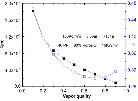
is shown in Fig. 8. It was obvious that the ratio decreases with vapor [image:13.595.172.425.68.275.2]quality increasing for refrigerant R134a in the annular flow pattern. It can be attributed to the reduction of liquid layer thickness nearby the heated wall. It also indicates that proportion of nucleate boiling reaches the minimum value when vapor quality equals 0.7.
Fig. 9 is the effect of heat flux at the wall on the ratio of nucleate boiling. It is seen that the ratio goes up with the increase of heat flux. The average value of the ratio is larger than 0.5, which indicates the dominant role of the nucleate boiling.
0.0 0.2 0.4 0.6 0.8 1.0 0.0
4.0x10⁻⁴ 8.0x10⁻⁴ 1.2x10⁻³ 1.6x10⁻³ 2.0x10⁻³
Vapor quality
m
106Kg/m
2
s 3.5bar R134a
40 PPI 90% Porosity 19KW/m2
0.28 0.32 0.36 0.40 0.44 0.48
[image:13.595.153.441.558.770.2]Fig. 8Composition of heat transfer for flow boiling
0 50 100 150 200 250 0.2
0.3 0.4 0.5 0.6 0.7 0.8
Mass flow rate(Kg/(m2S))
q=19KW/m2
q=100KW/m2
3.5bar R134a x=0.5
40 PPI 90% Porosity
Fig. 9Effect of heat flux on nucleate boiling
The effect of microstructure of metal foams on heat transfer is analysed in Fig. 10. From the analysis above, convective boiling heat transfer is influenced by the fibre diameter and pore diameter of the metal matrix. Fig. 10 shows that heat transfer of equivalent convective boiling and
forced convection is enhanced with the increase of
d
f/
d
p2. In addition, the differences of theheat transfer coefficients between these two cases in Fig. 10 become smaller when
d
f/
d
p2increases, indicating that forced convection plays more dominant role with increasing
d
f/
d
p2. [image:14.595.179.425.121.331.2]100 200 300 400 500 600 700 0.0
4.0x10³ 8.0x10³ 1.2x10⁴ 1.6x10⁴ 2.0x10⁴
h
(
W
/m
2 K
)
df/dp2(m-1)
Equivalent convective boiling Forced convection
3.5bar R134a x=0.5
[image:15.595.164.431.76.296.2]106Kg/m2s 19KW/m2
Fig. 10Effect of metal foams on heat transfer performance
0.2 0.3 0.4 0.5 0.6 0.7 0.8 6000
6200 6400 6600 6800 7000
h
(
W
/m
2 K
)
Vapor quality
6.0bar 3.5bar
106Kg/m2s R134a Annular flow pattern
20 PPI 1.4m fibre diameter 19KW/m2
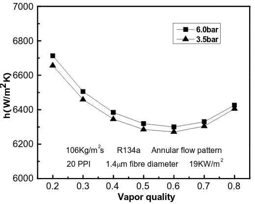
Fig. 11Effect of saturated pressure on heat transfer performance
6. Conclusions
A newly simplified microstructure model of metal foams has been developed, and the equivalent heat transfer coefficient for flow boiling in metal-foam filled tube is analytically studied based on the microstructure model and fin analysis method. It is found that the fibre diameter, surface area
density of metal foams and heat transfer coefficient predicted by analytical approach show quite good agreement with experimental data by other researchers. The weight of nucleate boiling is reduced with the increase of vapor quality and the decrease of the heat flux at the wall. The equivalent heat transfer coefficients of flow boiling and forced convection can be increased with
increasing
d
f/
d
p2, whilst the influence of saturated pressure is limited under annular flow [image:15.595.169.429.333.541.2]Acknowledgements This work is supported by the National Basic Research Program (2006CB601203), the National Natural Science Foundation of China (50806057) and the Engineering and Physical Sciences Research Council (No: EP/F061439/1) .
References
1. Rohsenow WM (1953) Heat Transfer with Evaporation . In: Chapter Heat Transfer, A
Symposium Held at the University of Michigan, University of Michigan Press, pp. 101-150
2. Dengler CE, Addoms JN (1956) Heat Transfer Mechanism for Vaporization of Water in a Vertical Tube. AIChE Chem Eng Progress Symp Ser 52: 95–103
3. Chen JC (1966) A Correlation for Boiling Heat Transfer to Saturated Fluids in Convective Flow. Ind Eng Chem Process Des Dev 5: 322-329
4. Mo B (2007) Numerical Evaluation of Heat Transfer and Pressure Drop in Open-cell Foams. M.S Thesis, University of Florida
5. Krishnan SM, Murthy JY, Garimella SV (2006) Direct simulation of Transport in Open-cell Metal Foam. ASME J Heat Transf 128: 793-799
6. Krishnan SM, Garimella SV, Murthy JY (2008) Simulation of Thermal Transport in Open-cell Metal Foams: Effect of Periodic Unit Cell Structure. ASME J Heat Transf 130: 024503-1-5
7. Boomsma K, Poulikakos D, Ventikos Y (2003) Simulation of Flow through Open Cell Metal Foams Using an Idealized Periodic Cell Structure. Int J Heat Fluid Flow 24: 825-834
8. Murthy S, Joshi Y, Gurrum S, Nakayama W (2006) Enhanced Boiling Heat Transfer Simulation from Structured Surfaced: Semi-analytical Model. Int J Heat Mass Transf 49: 1885-1895
9. Wang CY, Cheng P (1997) Multiphase flow and heat transfer in porous media. Adv Heat Transf 30: 93-196
10. Zhao C Y, Lu W and S A Tassou, (2009) Flow boiling heat transfer in horizontal metal foam tubes”,ASME J. of Heat Transfer, 131:121002-1-8.
11. Lu W, Zhao CY (2009) Numerical Modeling of Flow Boiling Heat Transfer in Horizontal Metal-foam Tubes. Adv Eng Mater 11: 832-836
12. Pastuszko R, Poniewski ME (2008) Semi-analytical Approach to Boiling Heat Fluxes Calculation in Subsurface Horizontal and Vertical Tunnels. Int J Therm Sci 47: 1169-1183