Abstract— All-IP network architecture is fast becoming a norm in mobile telecommunications. The International Telecommunications Union – Radio communication sector (ITU-R) recognizes a technology as 4G after haven met the International Mobile Telecommunications Advanced (IMT-A) specification of a minimum of 100Mb/s downlink data rate for high mobility and 1Gb/s for low mobility. Advent of Long Term Evolution by 3GPP, providing a minimum downlink data rate of 100Mb/s, marked a new beginning in Radio Access Technologies (RATs). It also notably implements an all-IP network architecture, providing higher data rates, end-to-end Quality of Service (QoS) and reduced latency. This paper aims at providing a technical overview of 3GPP LTE. Starting from a brief overview of its network architecture, this paper aims at exploring some key features of LTE that places it at the forefront in achieving the goals of wireless access evolution, enabling it to become a key element of the ongoing mobile internet growth. This paper also highlights two key aspects of LTE that are currently research intensive, and is wrapped up with the technological advancements on LTE.
Index Terms—4G, LTE, LTA, IMT-A, GSM, UMTS, E-UTRAN
I. INTRODUCTION
HE International Telecommunications Union – Radio communication sector (ITU-R) recognizes a technology as 4G after haven met the International Mobile Telecommunications Advanced (IMT-A) specification of a minimum of 100Mb/s downlink data rate for high mobility and 1Gb/s for low mobility. LTE is a major step towards meeting these IMT-A requirements as it is characterized by some of the features considered for 4G systems. As at February 2014, the Global mobile Suppliers Association (GSA) confirmed a total of 274 LTE networks launched in 101 countries thus far, with majority deployed on the 1800MHz frequency band [1]. LTE is a phenomenal technology – it enables operation under a vast set of conditions and still delivers excellent performance. This paper highlights the techniques LTE employs as well as the growth of LTE thus far.
Manuscript received March 18, 2015; revised April 13, 2015.
Oluwadamilola. I. Oshin is with the Department of Electrical and Information Engineering, Covenant University, Ogun State, Nigeria (+2347087907028; e-mail: damilola.adu@covenantuniversity.edu.ng).
Aderemi. A. Atayero is a Professor of Communication Engineering with the Department of Electrical and Information Engineering, Covenant University, PMB 1023 Ota, Ogun State, Nigeria (e-mail: atayero@covenantuniversity.edu.ng).
II. WHAT IS LTE?
LTE (Long Term Evolution) was developed and standardized by 3GPP as Release 8. It builds on 3GPP GSM/UMTS cellular concept and uses E-UTRAN (Evolved-UMTS Terrestrial Radio Access Network) as its radio access: it is therefore sometimes referred to as E-UTRAN. Compared to previous 3GPP telecommunication standards, LTE marks a departure from the normal circuit switched or a combination of circuit and packet switched networks, to an all-IP/packet-based network. LTE is a wireless access technology, which provides high quality experience.
3GPP LTE is a significant advancement in cellular technologies. The motivations for LTE as outlined by 3GPP are: need to ensure the continuity of competitiveness of the 3G system for the future, user demand for higher data rates and quality of service, packet-switched optimized system, continued demand for cost reduction (Capex and Opex), low complexity and to avoid unnecessary fragmentation of technologies for paired and unpaired band operation [2].
Wireless access technology evolution aims at achieving the following: rich experience and high performance, connectivity, coverage and roaming, ecosystem richness, efficiency and cost effectiveness. Starting from a brief overview of its network architecture, this paper aims at exploring the access technology elements of LTE that places it at the forefront in achieving the goals of wireless access evolution, enabling it become a key element of the ongoing mobile internet growth. This paper also highlights two key aspects of LTE that are currently research intensive, and is wrapped up with the technological advancements on LTE.
III. LTENETWORK ARCHITECTURE
LTE network architecture is a generally simplified access network which marks a total departure from previous standards, characterized by the absence of a circuit-switched domain. It employs a non-hierarchical (distributed) structure. The LTE network architecture incorporates new network elements.
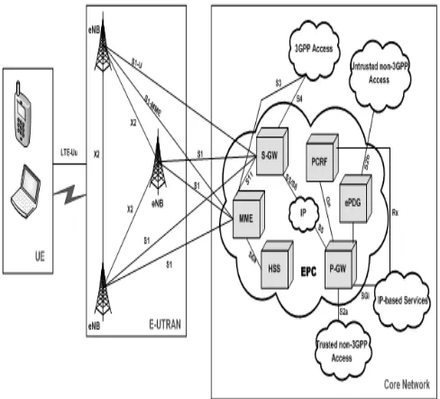
As shown in Figure 1, LTE network architecture can be sub-divided into three major groups: air interface, radio access network and core network.
3GPP LTE: An Overview
Oluwadamilola I. Oshin and Aderemi A. Atayero, Members, IAENG
Fig. 1. LTE Network Architecture.
A. Air Interface
All transmissions of data and control information between the user equipment (UE) and the evolved base stations (eNBs) take place within the air interface. LTE uses various mechanisms (as discussed later in this paper) within the air interface to provide highly reliable and efficient means of carrying out these operations.
B. Radio Access Network (RAN)
Import The RAN of LTE consists only of a network of fully interconnected eNBs; hence the network is described as being flat or distributed. This RAN is called the E-UTRAN i.e. the Evolved-UMTS Terrestrial Radio Access Network. It is an evolved RAN from UTRAN, used by 3G networks but in LTE, all radio network controller (RNC) functions are transferred to the eNBs. The functions of the eNB therefore include:
Radio Resource Management: This handles functions such as scheduling, dynamic allocation of resources, radio bearer control and mobility control.
IP Header Compression.
Security
Connection to the core network.
C. Core Network
This is a major area where LTE differed from previous standards. All others had their core networks either entirely circuit switched or split into circuit switched domain and packet switched domain, but LTE core network is entirely packet switched and it is called the Evolved Packet Core (EPC). The EPC in conjunction with the E-UTRAN is called the Enhanced Packet System (EPS), whose details have been defined by 3GPP’s study of System Architecture Evolution (SAE).
A Summary of the functional elements of the EPC are outlined below [3]:
Mobility Management Entity (MME): this handles user authentication, it tracks and maintains the location of a user equipment, performs signalling operations, MME selection for inter-MME handovers.
Serving Gateway (S-GW): while the MME handles control distribution functions, the S-GW handles data bearer functions where it handles user data functionality, routes and forwards data packets to the P-GW, performs mobility anchoring for inter-3GPP mobility and is responsible for lawful interceptions.
Packet Data Network Gateway (P-GW or PDN-GW): It handles packet filtering for every user, allocation of IP addresses to the UEs, supports service level charging by collecting and forwarding call data records, handles DL data rate enforcement to ensure that a user does not surpass his traffic rate subscription level, provides interworking for the user plane, between some 3GPP access systems and all non-3GPP access systems, supports QoS differentiation between multiple IP flows. It is also capable of handling multiple lawful interceptions of user traffic to promote government intelligence services fighting criminal activities. The P-GW enforces PCRF policies.
Home Subscriber Server (HSS): this is a major database, which houses all subscription-related information, to perform call control activities and session management functions.
Policy and Charging Control Function (PCRF): The PCRF ensures QoS regulation within the network based on definite policies. It is responsible for framing policy rules from the technical details of Service Date Flows (SDFs) that will apply to the users’ services, and then forwarding these rules to the P-GW for enforcement.
Evolved Packet Data Gateway (ePDG): The ePDG provides interworking with un-trusted non-3GPP IP access systems. It ensures security by having a secured tunnel between the UE and the ePDG. It can also function as a local mobility anchor within un-trusted non-3GPP access networks.
As observed in Figure 1, LTE uses interfaces as indicated for communication between its entities. In general, LTE network architecture implements a simplified, flat all-IP architecture which leads to reduced latency, reduced Capex and Opex, increased scalability and efficiency among other benefits.
shared in a finite frequency bandwidth i.e. it controls how to use (share) the radio resources efficiently. These operations take place within the air interface of the LTE network.
A. Orthogonal Frequency Division Multiplexing (OFDM)
The OFDM is a data transmission multi-carrier modulation technique, which divides a high bit-rate data signal into several parallel low bit-rate data signals which are then modulated using an appropriate modulation scheme. OFDM is the core of LTE downlink transmission system. Majority of the striking features of LTE is made possible by its use of OFDM. The “low bit-rate multi-carrier” technique of OFDM, with a cyclic prefix added to it, makes the transmission robust to time dispersion on the radio channel without the need for advanced and complex receiver channel equalization. In the downlink, this leads to reduced cost of terminal equipment and reduced power consumption as well. OFDM is also used due to its resilience to multipath delays and spread, its capability for carrying high data rates and its ability to support both FDD and TDD schemes.
B. Orthogonal Frequency Division Multiple Access (OFDMA)
In the downlink, the Base Station (BS) is the transmitter while the User Equipment (UE) only receives, therefore it does not have multiple access problems in terms of collisions. Fading is a natural characteristic of radio communication channels (either in time, frequency or space domain), resulting in rapid variations in radio channel quality. A derivative of OFDM – OFDMA is used in LTE downlink, where it combines functionalities of FDMA and TDMA. With OFDMA, the UE gets scheduled to a time slot and a frequency group (which makes the system resilient to frequency-selective fading) among other features, in order to send information. Using OFDMA, LTE can use channel-dependent scheduling to take advantage of the variations resulting in more efficient use of available radio resources. This creates a lot of flexibility and makes the system robust, as not all the requirements for transmission can be bad at the same time.
C. Single Carrier – Frequency Division Multiple Access (SC-FDMA)
In In the uplink, the UEs transmit to the BSs. Due to the high peak-to-average ratio (PAR) of OFDM (characterized by the high amount of power required by the RF power amplifier to push out the RF signal from the UE antenna to the BS), 3GPP was forced to adopt a different transmission scheme for LTE uplink. SC-FDMA, a hybrid scheme, was the solution – it combines the low PAR feature (which allows high RF power amplifier efficiency in the UEs, thereby reducing battery consumption for the UE) of single-carrier schemes with the resilience of multipath interference and the flexible subcarrier frequency allocation
of OFDM technology [4].
V. CODING AND MODULATION
The reduced latency and high throughput of LTE is traceable to a number of mechanisms implemented in it. The physical/MAC layer of LTE adopts two key techniques: Hybrid Automatic Repeat reQuests (HARQ) and adaptive modulation and coding (AMC). These two techniques work together to give a very adaptive transport mechanism in LTE [5].
To handle re-transmission errors, LTE uses two loops: a fast HARQ inner loop with soft combining to take care of most errors and a robust selective-repeat ARQ outer loop to take care of residual errors [6, 7]. HARQ is a technique for both error detection and correction by identifying when transmission errors occur and facilitating retransmission from the source thereby ensuring that data is transported reliably from one network node to another. LTE uses Type-II HARQ protocols.
LTE demonstrates dynamic resource allocation through link adaptation. Link adaptation is achieved using the AMC mechanism, with the aim of improving data throughput in a fading channel. AMC works by varying the downlink modulation technique depending on the channel conditions of each user. Given a good channel condition, the LTE system can use a higher order modulation scheme (64-QAM with 6 bits per symbol) or reduced channel coding, making the channel more spectrally efficient, and resulting in higher data rates. But as the channel becomes noisy due to signal fading or interference, the system selects a lower modulation technique (QPSK or 16-QAM with fewer bits per symbol) or stronger channel coding.
VI. RADIO ACCESS MODES (DUPLEX SCHEMES) A duplex scheme organizes how radio communication systems communicate in the two possible directions (uplink and downlink). 3GPP has specified LTE to operate in either unpaired spectrum for Time Division Duplex (TDD) called TD-LTE or paired spectrum for Frequency Division Duplex (FDD); where each has its pros and cons, therefore selection is made depending on the intended application.
LTE specifications emphasize on TD-LTE, as it presents significant advantages over LTE FDD. TD-LTE, asides many other advantages, provides an upgrade path for TD-SCDMA, it does not require a paired spectrum since uplink and downlink transmissions occur on the same channel making it highly spectrally efficient and TD-LTE also reduces hardware cost. LTE operation in FDD which is the same duplex method for GSM/UMTS, gives room for subscribers’ migration to LTE.
VII. RADIO CHANNEL BANDWIDTH
LTE is not only able to operate in different frequency bands, but can be implemented using different spectrum sizes. This makes it possible to harness the global wireless market and align with regional spectrum regulations and the obtainable spectrum. LTE implements a scalable radio channel bandwidth from 1.4MHz to 20MHz with a subcarrier spacing of 15kHz although, a 20 MHz bandwidth will be required for optimum performance and to cope with the growth of the mobile internet. 3GPP has specified the LTE air interface to be “bandwidth agnostic” thereby allowing the physical layer to adapt to different spectrum allocation without severe impact on system operation.
LTE defines an enhanced mode of operation for broadcast/multicast services called eMBMS (Enhanced- Multimedia Broadcast/Multicast Service), yielding notable performance benefits compared to MBMS over WCDMA. LTE does this by enabling the support of MBSFN (Multimedia Broadcast over Single Frequency Network) yielding a possible subcarrier spacing of 7.5kHz for standalone eMBMS operation using a dedicated carrier [9].
VIII. MULTIPLE ANTENNA TECHNIQUES
Every terrestrial radio communication channel has data throughput limitations as defined by Shannon’s theorem, and multipath interference. LTE networks are expected to provide high data rate in addition to high spectral efficiency; therefore, 3GPP included the use of multiple antenna techniques to provide additional robustness to the radio link [10]. Multiple antenna techniques take advantage of the effects of multipath interference to increase data throughput significantly within the channel’s given bandwidth. The use of multiple antenna techniques introduces the concept called precoding; this is essential for obtaining the best data reception result at the receiver. It specifically maps the modulation symbols onto the different antennas.
In selecting the type of multiple antenna technique to use, transmission modes were defined. 3GPP’s Release 8 (LTE) specifies seven transmission modes (named TM1, TM2 e.t.c.) for the downlink and one transmission mode for the uplink. These antenna techniques differ by the benefit they provide and the conditions required for their operation. The transmission modes differ in the number of layers or ranks and the number of antenna ports. The uplink transmission mode is Closed-loop switched antenna diversity. The downlink transmission modes are:
TM1 Single antenna TM2 Transmit Diversity
TM3 Open-loop spatial multiplexing – Cyclic Delay Diversity (CDD)
TM4 Closed-loop spatial multiplexing TM5 Multi-user MIMO (MU-MIMO) TM6 Closed-loop single layer precoding TM7 Beamforming
IX. VOICE OVER LTE/IPMULTIMEDIA SUBSYSTEM (IMS) OVERVIEW
LTE implements an all-IP architecture; this implies that voice communication cannot be “business as usual” i.e. voice communication cannot be circuit-switched as it is with lower generation technologies. This problem also applies to SMS communication as well; therefore, new solutions for supporting voice and SMS on LTE network became an urgent need.
In order to provide these very crucial services, alliances were tasked to come up with solutions to these shortcomings, which are listed below:
Circuit-Switched Fall-Back (CSFB): This method involves the use of a 2G/3G network alongside the LTE network. The LTE network is used for data services but on a call initiation, the network falls back to a 2G/3G circuit-switched connection while the LTE network (packet-switched) is suspended. For an SMS transmission, the mobile equipment uses an interface known as SGs (MME-MSC interface) which allows messages to be transmitted over an LTE channel.
Simultaneous Voice – LTE (SV-LTE): This is very similar to the CSFB but in SV-LTE, the user device makes use of the 2G/3G network and the LTE network concurrently. Thus, when a call is initiated, it is routed through the circuit-switched 2G/3G connection while maintaining connection with the LTE network. This option requires the use of two radios simultaneously by the mobile device which causes a degrading impact on the battery life of the device.
Over-the-top (OTT) VoIP: An example of an OTT VoIP solution is Skype. This concept led to the widespread usage of VoIP as a voice communication service and has advanced to an era of being pre-installed in smart phones. However, OTT VoIP solutions cannot guarantee satisfactory user experience in the absence of LTE coverage. OTT VoIP service providers do not have control over QoS in the wireless network, therefore, cannot ensure a good quality of experience (QoE) under all load circumstances. It also lacks the capability of handing over to a circuit-switched connection.
SMS over the intermediate LTE network.
Voice over LTE (VoLTE): This method implements 3GPP’s IMS core network by deploying Multimedia Telephony (MMTel) on the IMS core as the solution for voice service delivery and other traditional circuit-switched services over the LTE network. VoLTE eliminates the need for fall-backs to 2G/3G voice, ensuring a truly flat all-IP LTE network. With VoLTE users are assured telecom grade voice and all forms of rich communication services on LTE-enabled devices. VoLTE defines three working interfaces:
The User Network Interface (UNI): This is the interface between the user device and the operator’s network.
The Roaming Network NetworkI nterface (R-NNI): This is the interface between the Home and Visited Network, for use in a roaming situation.
The Interconnect Network Network Interface (I-NNI): This is the interface between the networks of the two users making a call.
VoLTE has been accepted globally by a significant number of telecom industries as the standard for carrying voice, SMS and other related services over the LTE network [11].
X. SELF ORGANIZING NETWORKS (SON)
The impact or functionality of a network is not just in its deployment and usage but in its ability to achieve operational excellence. This involves continuous end-to-end network management of the system i.e. seamless operation and consistent performance. Due to the increasingly expanding and evolving wireless network, there is a crucial need to automate this management process [12, 13]. In order to achieve this, LTE adopts SON techniques which enables the network to configure itself and manage the radio resources to achieve optimum performance at all times with minimal human supervision. SON techniques cover three main areas:
Self Configuring: As a network expands and more eNBs are deployed, self configuring networks eliminate the need to go around configuring each one; rather, they are configured using automatic installation procedures.
Self Optimizing: After configuration, self optimizing techniques adjust the network’s operational characteristics based on measurement information collected from the UEs and eNBs, and use them to auto-tune the network to best meet its needs.
Self Healing: In any system, faults are very likely to occur; however, the self healing capability of a network enables automatic detection and fault masking by changing relevant network
characteristics. For example, edges of adjacent cells can be increased by raising power levels and changing antenna elevations.
XI. LTETECHNOLOGICAL ADVANCEMENTS
There are two groups of technological advancements on LTE Release 8, namely LTE Release 9 and LTE Release 10 [14].
Transmission Mode 8 (TM8), Dual Layer Beamforming, was added in LTE Release 9. LTE Release 9 also focuses on features that enhance the core network of LTE Release 8. These enhancements centre on:
Location, broadcast and IMS emergency services using GPRS and EPS.
Support of circuit switching services over the EPS of LTE
Home NB or eNB architecture considerations focusing on security, QoS, charging and access restrictions
IMS evolution
LTE Release 10: This is the evolution of LTE to meet the IMT-A requirements defined by ITU. It is known as LTE-Advanced (LTE-A), and its focus is on higher capacity as outlined:
Downlink peak data rate of 3Gb/s and Uplink peak data rate of 1.5Gb/s.
Higher spectral efficiency on the downlink, from an upper limit of 16bps/Hz in Release 8 to 30bps/Hz in Release 10
Increased number of simultaneously active subscribers
Improved performance at cell edges
LTE-A centres on three new techniques that enable it achieve the above-mentioned feats [15]:
Carrier Aggregation (CA): The most basic method of increasing capacity is by adding more bandwidth. LTE-A is increased in bandwidth through aggregation of up to five component carriers of different bandwidths to form a maximum bandwidth of 100MHz. This also provides LTE-A backward compatibility with Release 8 and Release 9 mobiles. Carrier aggregation can be used in both FDD and TDD schemes.
Enhanced multiple antenna techniques: It adds a ninth transmission mode to the downlink called Eight Layer Spatial Multiplexing (8x8 MIMO), and adds a second transmission mode to the uplink (4x4 MIMO).
Coordinated Multipoint (CoMP) Transmission/ Reception: This feature was finalized in Release 11. In this technique, multiple transmit and receive points provide coordinated transmission/ reception. This transmission/ reception is carried out jointly and dynamically across multiple cell sites, same site or within same or different eNBs. The primary purpose of CoMP is to improve the performance at cell edge.
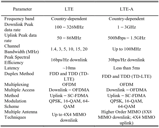
Table 1 below gives a summary of the key characteristics of LTE at its inception and the current features of LTE as at today, LTE-A. However, recall that there are improvements on the first release of LTE as already discussed in this sub-section, before the LTE Release 10 (LTE-A).
TABLEI LTE–LTE-ACOMPARISON
Parameter LTE LTE-A
Frequency band Country-dependent Country-dependent Downlink Peak
data rate 100 – 326MHz 1 – 3GHz Uplink Peak data
rate 50 – 86MHz 500Mbps – 1.5GHz Channel
Bandwidth (MHz) 1.4, 3, 5, 10, 15, 20 Up to 100MHz Peak Spectral
Efficiency 16bps/Hz downlink 30bps/Hz downlink
Latency ~10ms Less than 5ms
Duplex Method FDD and TDD
(TD-LTE) FDD and TDD (TD-LTE)
Multiplexing OFDM OFDM
Multiple Access Method
Downlink – OFDMA Uplink – SC-FDMA
Downlink – OFDMA Uplink – SC-FDMA Modulation
Scheme
QPSK, 16-QAM, 64-QAM
QPSK, 16-QAM, 64-QAM Multiple Antenna
Techniques Up to 4X4 MIMO downlink
Higher Order MIMO (8X8 MIMO downlink; 4X4 MIMO
uplink) .
XII. CONCLUSION
It is most evident that LTE brings about a win-win situation for the users and network operators. It gives sustainable and significant advantages over existing 3G technologies and also offers the most efficient and feasible evolution path as user/operator network demands mature.
REFERENCES
[1] “GSA confirms 1800 MHz as the most popular LTE band; LTE1800 used in over 37% of networks”, Online, available: http://www.gsacom.com/news/gsa_367.php, accessed: 11.11.2014. [2] Oni O.O., Atayero A.A., Idachaba F.E, Alatishe A.S.. "LTE Networks:
Benchmarks, Prospects and Deployment Limitation." In Proceedings of the World Congress on Engineering, vol. 1. pp. 422-427, Available: http://www.iaeng.org/publication/WCE2014/WCE2014_pp422-427.pdf 2014.
[3] Dino Flore, “LTE RAN architecture aspects,” IMT-Advanced Evaluation, Beijing, China, December 2009.
[4] Ian Poole, “LTE OFDM, OFDMA and SC-FDMA,” Adrio Communications Ltd.
[5] Agilent Technologies, “3GPP Long Term Evolution: System overview, product development and test challenges,” Application note, 2009.
[6] Anders Furuskar, Tomas Jonsson and Magnus Lundevall, “The LTE Radio Interface – Key Characteristics and Performance,” in IEEE, 2008. [7] Davis Astely et al., “LTE: The Evolution of Mobile Broadband,” IEEE
Communications Magazine, April 2009.
[8] A. Z. Yonis, M. F. L. Abdullah and M. F. Ghanim, “LTE-FDD and LTE-TDD for cellular communications,” Progress in Electromagnetics Research Symposium Proceedings, KL, Malaysia, March 2012. [9] 3G Americas, “The Evolution of Rel7 to Rel8 – HSPA and SAE/LTE,”
A Whitepaper, June 2008.
[10] Yair Shapira, “LTE Multiple antenna techniques,” Exploregate. [11] Dan Warren, “Roaming in LTE and Voice over LTE,” GSMA
Association, 2010.
[12] Atayero A.A., Adu O.I, Alatishe A.A. "Self Organizing Networks for 3GPP LTE." In Computational Science and Its Applications–ICCSA 2014, pp. 242-254. Springer International Publishing, 2014.
[13] Sujuan Feng and Eiko Seidel, “Self-Organizing networks (SON) in 3GPP Long Term Evolution,” Nomor Research, Munich, Germany, May 2008.
[14] 3G Americas, “3GPP Release 8 and beyond,” A Whitepaper, February 2009.
[image:6.595.45.310.271.484.2]