Abstract— The reverse shoulder implant is an implant for total replacement of the glenohumeral joint of patients suffering from osteoarthritis and with a damaged rotator cuff. The problem that arises with these conjoined ailments is that the displacement of the humeral head causes limited movement of the upper limb, with vertical mobility restricted to only allow for the arm to ascend to roughly the height of the shoulder. Attaching the ball to the scapula and the socket to the top of the humerus fixes the centre of rotation of the joint to increase the moment arm over the healthy shoulder’s original position enabling patients’ movement and dexterity to return. In this study the numerical evaluation of a Verso Shoulder Implant (Biomet, UK) was carried out and the mechanical parameter such as stress, strain and deformation at the interface between the glenoid and scapula bone was analysed.
Index Terms— Verso Shoulder Implant, Finite Element, rotator cuff.
I. INTRODUCTION
The human shoulder is a complex joint system that allows for a great range of movement of the arm. It is made up of three bones: The humerus, scapula and clavicle.
The study focused on the joint between the humerus and scapula known as the glenohumeral joint, around which act a group of muscles known as the rotator cuff whose role is to pull the humeral head into the glenoid of the scapula and assist with the arm flexion, extension, adduction, abduction, rotation and circumduction. The rotator cuff is made up of four muscles; the supraspinitous, infraspinitous, subscapularis and teres minor. The shoulder plays a very important part in making the motion of the arm the most uninhibited in the body. Coupled with how hugely dependent many daily activities are on the mobility and dexterity of the arms means that any problem that occurs
Manuscript received March 06, 2016; revised April 06, 2016. All of the authors have no financial relationship to any private organizations.
Francis Popham is with Mechanical, Aerospace and Civil Engineering Department, College of Engineering, Design and Physical Sciences, Brunel University London, UK
Janith Muhandiram (corresponding author) is with Mechanical, Aerospace and Civil Engineering Department, College of Engineering, Design and Physical Sciences, Brunel University London, UK. Tel. - +447931999858. Email – [email protected]
Nesreen Abulkhair is with Mechanical, Aerospace and Civil Engineering Department, College of Engineering, Design and Physical Sciences, Brunel University London, UK
Mahmoud Chizari is with the School of Mechanical Engineering, Sharif University of Technology in Tehran. He is also with Orthopaedic Learning and Research Center at Brunel University London, Uxbridge, UB8 3PH, UK. Fax: +44 1895256392, E-mail: [email protected]
with the function the shoulder can cause great distress, both mentally and physically.
One of the most detrimental problems that arise regarding the movement of the shoulder occurs at the glenohumeral joint, where the erosion of the solid cushioning known as cartilage and the lubricated synovium causes the bones to rub together when moving. This is known as arthritis of which there are two types that prevail in the shoulder. Osteoarthritis is a common occurrence caused by constant exposure of the joint to high stresses. Rheumatoid arthritis occurs when the synovium enflames destroying the bone and cartilage it encompasses. The direct contact of the two rough bony surfaces causes many problems including stiffness of joints and pain and therefore must be treated by surgery. Although, there are non-intrusive methods of treatment they will not enable regrowth of the cartilage and are therefore seen more as pain management.
The surgical method to cure arthritis is a specific form of orthopaedic surgery called total replacement arthroplasty, which is where the ends of the joints are cut off and replaced with a man-made imitation. In total shoulder replacement this involves replacing the head of the humerus with a metal hemisphere and the glenoid cap in the scapula with a polyethylene cup. The problem with this method is that any musculoskeletal problems the patient had prior to surgery, which were not due to the geometry of the joint but to the supportive muscles, will still be prominent with the new shoulder, specifically when that restriction is caused by a loss of strength, or tear of the rotator cuff muscles.
The objective of this project is to examine the mechanical behaviour of the glenoid interface of a shoulder fitted with a Biomet Verso Shoulder implant (Biomet, UK) by using finite element analysis when the joint is subjected to high impact loading. This specific interface has been chosen because this is the most common area of failure in reverse shoulder implants which could possibly be due to stress levels of the screws and/or bone exceeding their material yield strengths or large displacements of any of the parts, which make up the joint, when subjected to considerable loading.
This can be solved by using a reverse shoulder implant like the Verso Shoulder, which switches around the position of the ball and socket of the shoulder. Attaching the ball to the scapula and the socket to the top of the humerus fixes the centre of rotation of the joint to increase the moment arm over the healthy shoulder’s original position enabling patients’ movement and dexterity to return. Patients who undergo this procedure are able to apply muscular forces from the deltoid muscle to the joint much more efficiently than before enabling a much greater range of movement.
Biomechanical Aspects of the Scapula-Glenoid
Fixation in a Reverse Shoulder Implant
(a) (b) Fig 1: (a) X-ray of Shoulder Implant (c) Verso Implant [1]
Previous study by Kontaxis has shown that there are mechanical benefits with an increased moment arm allowing for weaker rotator cuff muscular forces along with the deltoid to act more efficiently on the joint. The main concern is that the device reverses the natural joint leading to the speculation of possible physical and mechanical anomalies which would not have previously occurred. Holcomb [3] showed that the main area of failure in reverse shoulder arthroplasty was the screws and insets at the interface of the implant and scapula with the continual movement of the arm leading to an ever increasing degree of damage.
Failure in this area tends to be down to two factors. The first is that the implant parts are overloaded, either due to incorrect geometry or positioning of the sphere of the implant causing the natural muscular forces to apply forces which the implant has not been designed to take, or from experiencing a considerably high impact load through the arm. The former is down to the fitting of the implant while the latter is down to the design of the implant, which can be analysed in order to see, theoretically, how the joint will react. The second main factor for failure is down to how the bone surrounding the implant repairs itself. Bone is a living material and needs to be put under stresses and small displacements in order to strengthen. In order for the bone to grow denser around the implant, it requires a micromotion range of between 50 and 150 micrometers. Any less and the bone will not be encourage to strengthen, anymore and the bone will be damaged.
One method of analysing the stresses and micromotion within the implant is by running a finite element analysis (FEA) on a computational representation of an implant, which has previously been used to compare healthy and arthritic shoulder joints. The research carried out by Büchler [4] showed the stress distribution over the scapula with varying positions of the humeral head on a healthy and arthritic shoulder using FEA.
The results showed that stresses within the scapula were more evenly distributed in the healthy shoulder with lower maximum stresses than in the arthritic shoulder, whose stresses were considerably localised. It is this effect of exponentially increased damage through increasing stress localisation that leads to surgery being the only effective method of curing osteoarthritis.
In order to see how effective the reverse shoulder implant is in overcoming the problems caused by arthritis and degraded rotator cuff, Kontaxis [5] compared the movements used in activities of daily life of those with an implant (test group) to those with a healthy shoulder (control group) by using motion analysis. Although limited in rotational movements that required the rotator cuff muscles,
the movements made by the test group that were dependant on the deltoid were very similar to the control group showing that the reverse shoulder implant does improve the range of motion. This study will be continuing on previous research into the mechanical properties of a reverse shoulder implant carried out by Hopkins and Virani [6] in which different reverse shoulder implants were set into polyurethane foam, representing cancellous bone, and loaded axially, from which the displacements were measured and the results compared to those taken from FEA. These studies set out to identify the motion and stresses of numerous implants under loading, as opposed the internal stresses in the bone. This study will analyse the stresses that build up around the glenoid joint as well as the deformation of the screws within the scapula. By using precise geometry of the scapula rather than a solid block, it will be possible to observe how the natural shape of the bone reacts to the unnatural arrangement of the joint. The objective of this project is to examine the mechanical behaviour of the glenoid interface of a shoulder fitted with a Biomet Verso Shoulder implant (Biomet, UK) by using finite element analysis when the joint is subjected to high impact loading. This specific interface has been chosen because this is the most common area of failure in reverse shoulder implants [3] which could possibly be due to stress levels of the screws and/or bone exceeding their material yield strengths or large displacements of any of the parts, which make up the joint, when subjected to considerable loading. What the results should show is how the design and geometry of the Verso Shoulder should react to high loads and whether its design would need to be evaluated. The finite element method will be used as this is one of the few methods which are easily accessible that will be able to show all the mechanical behaviour that occurs within a relatively small, inaccessible area.
II. METHODOLOGY
I.
Scenarios
Three different scenarios were analysed for this study. The first two only examined the scapula side of the skeletal-prosthetic joint, namely the glenoid sphere, baseplate and screws, and used the same loading conditions used for the research carried out by Hopkins [7], in which an axial load of 756N and a vertical force of 756N were applied to the glenoid head representing a high impact loading. The direction and magnitude of the resultant force of 1,070N would be similar to a person using their arm to stop themselves when falling. As in Hopkins’ report the first scenario used a solid cuboid block in order to represent the scapula, after which the same forces were applied but using the model of the scapula. This was done in order to show if there are any differences between the results due to the bone geometry.
The final scenario was a much more comprehensive examination using all the parts of the implant and both the bones. The resultant force used for the previous analyses was then applied acting through the humerus in the direction of the glenohumeral joint.
II.
Model Geometry
model on which the analysis will be carried out by using Mimic (Materialise BV, Leuven, Belgium) software. The Verso Shoulder is a product of Biomet (Biomet, UK), conscribed by the Reading Shoulder Unit and is just one of many reverse shoulder prosthetics that surgeons use for this procedure. The geometry of the bones was also obtained in this way but by using Sawbones as the scanning subject. The CT scans were done prior to the study by Reading Shoulder Unit.
As the model came, there were a number of problems with the geometry which needed rectifying. The first, most obvious problem was that the humerus and scapula had no recesses for the implant to be fitted into. This was solved using the Boolean cut tool which removed the shape of the intrusion of the implant into the bone. Before this could be done however, the current hole on the scapula would need filling in first as there were problems with its geometry, and the second screw which attaches the baseplate to the scapula needed to be created using the rotate pattern tool. Also the baseplate was not properly aligned with the hole in the scapula and so needed moving before the new screw could be created in order to get it into the correct position.
III.
Material Properties
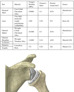
The material properties of the implant parts were provided by Reading Shoulder Unit; taken from Biomet (Biomet, UK), Matweb (Matweb, US) and a study on ultra-high molecular weight polyethylene carried out by Kurtz [8]. The mechanical properties of the bone have been modelled to be that of cancellous bone rather than cortical bone as it is this softer, spongy material which has contact with the implant. It will also be idealised to have linear mechanical properties which is adequate for most studies of bone stress and strain [9].
Part Material
Young’s Modulus (MPa)
Poisson’s Ratio
Density (tonne/mm3
) Source
Humeral Shell
Cast Cobalt Chromium Alloy
230000 0.3 8276 Manufacture r
Liner
Ultra high molecular weight polyethylene (UHMWPE)
1290 0.38 935 Kurtz [8]
Glenoid Sphere
Wrought Cobalt Chromium Alloy
241000 0.3 8276 Manufacture r
Glenoid
Baseplate Wrought
Titanium Alloy 114000 0.34 4430 Matweb [10] 2x Screws
Humerus Cancellous
[image:3.595.351.503.377.574.2]Bone 372 0.26 282 Mansat [11] Scapula
Fig 2: 3D Model of the Human Shoulder
The next step was to define interactions in order for Abaqus/CAE to know which surfaces of each part were in contact. Each interaction set up was specified as a frictionless surface contact as the interest was not on the frictional shear stresses. Once the interactions had been set the full assembly, as shown in Fig 1, was complete.
Forces and Boundary Conditions on the full shoulder model included the humeral section of the assembly and was loaded with the same force of 1070N but acting at the top and bottom of the humerus. Although a body force would have been preferable it was not possible to specify the precise direction of the load so a concentrated force was used spilt over 25 of the upper and lower nodes. This meant the force needed to be divided by 50 as the load specified acts on each chosen node. As before the force acting through the humerus represented an impact load and the results obtained should lead to a more realistic stress distribution across the glenoid due to the load not being applied directly through the end point of the sphere.
[image:3.595.40.291.452.764.2]The assembly of the final model required the meshing of all parts of the humeral side. As the focus of the project was the glenoid interface this area was not going to be analysed in great depth and so the mesh density assigned was relatively low, without overly sacrificing the geometry, in order to minimise the computational time.
Fig 3: Boundary Conditions and Gravitational Forces Acting on the Shoulder Model
IV. RESULTS
possible to compare the distribution of the stresses and points and magnitudes of the maximum stresses. The maximum stress results for all models were also compared to the compressive yield strengths (4.8 MPa for Cancellous Bone [12]) in order to see if, theoretically, there would be any damage to the scapula or screws caused by the impact force.
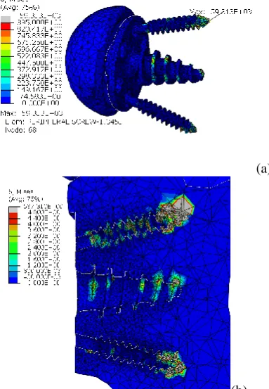
The stresses in the full shoulder model show a similar trend to the ones in the simplified shoulder model. The maximum Von Mises stress is 59.313GPa and occurs at the tip of the upper screw, shown in Fig a.
Fig 4: Von Mises Stress on Full Model
(a)
(b)
Fig 5: (a) Maximum Point of Stress in Full Shoulder Model; (b) Stresses on the Bone in the Full Shoulder Model
The stresses on the scapula in the full shoulder also show many similarities between the simplified shoulder model. The maximum stress is slightly lower at 597MPa but the points of high stress are still at the ends of the screws. There is a slight increase of stress induced by the baseplate screw over the simplified shoulder shown by the yellow circle. The stress experienced by the glenoid face is also low, however there is a small point towards the right edge of increased stress of between 2.4-2.8MPa.
The deformation of the bone in the glenoid interface due to the impact loading is shown in Fig 6. The maximum deformation is shown by the yellow circle at a magnitude of 627µm. This is considerably higher than the 150µm required for the bone to regrow around the implant. It is possible to see the deformation between 50µm and 150µm in the second picture showing that only very specific areas around the baseplate screw which are in this range.
(a) (b)
Fig 6: Deformation of the Scapula in Full Shoulder Model between (a) 0mm to 0.63mm and (b) 0.05mm to 0.15mm
V. DISCUSSION
Failure of reverse shoulder implants typically occurs at the interface of the scapula and it was for this reason that this interface was chosen for analysis by FEA. What the results show is that the level of stress experienced at the interface of the baseplate, screws and scapula is far greater than the compressive yield strength of the materials of the parts under analysis. The result of these high stresses in a real life implant would be failure of the screws and damage to the surrounding bone in the scapula as shown in the radiograph data [3].
The results of FEA show considerable stresses acting on the bone and the screws within the scapula for all three cases, showing that the force applied to the glenoid head is distributed by the baseplate through the screws. The problem is that the screws themselves have an incredibly small cross sectional area of only 3mm in diameter. This is due to the fact that the area of the glenoid itself, where the baseplate and screws are attached, is very small and so there is not a lot of room for manoeuvre regarding designing larger screws.
The most common point of failure for screws is roughly in the area where the thread starts as it tends to experience a higher stress due to the change in geometry causing a stress raiser. Fig shows an increase in the stress levels around the first thread on the screws however only the simplified block screws have exceeded the yield strength, most likely due to the higher overall stresses experienced.
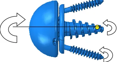
[image:4.595.304.539.153.284.2] [image:4.595.50.208.188.335.2] [image:4.595.50.242.365.642.2]This is an average approximation of the stress which the screw would be subjected to under this type of loading across its cross sectional area. The stress of 7.56MPa is far below the yield stress of titanium leading to the conclusion that there must be another aspect inducing these stresses such as a moment force acting on the screw tips. It is possible to extrapolate that the stresses acting the screw thread and tip will be of a much higher order as their area reduces significantly. This would account for the high values of stress at the tip of the screws shown in the results. The results from the three cases were relatively consistent in that the areas of high stress concentration were all around the interface of the screws and bone, both in the scapula and screws themselves. This shows that there must be a turning moment acting perpendicular in the horizontal to the centreline of the baseplate due to the vertical component of the load from which the reactant moment from the scapula would cause an increase in stress. As there is an axis of symmetry through the centreline the same turning moment would be applied to both the screws and so similar stresses would occur. This can be seen where the stress is localised around the screw tips.
Assuming that the turning moment is the cause for such high stress it is possible to deduce that the centre of rotation must be close to, if not actually at the tip of the baseplate screw. This would explain the comparatively low stresses acting at this interface as it would only be experiencing a compressive axial force with possibly a small reaction moment force.
Fig 7: Suggested Direction of Turning Moment with Estimated Centre of Rotation and Reaction Moments
Another reason for these stress increases would be from the upward tangential movement of the baseplate causing the threads of the lower screw to pull against the bone and the threads and tip of the upper screw to push against the bone. The proof of this can be seen in the results where the upper screw hole experiences more stress on the upper side of the base of the hole. A turning moment acting clockwise would induce stress on the lower surface as the screw would push down. This also accounts for the maximum point of stress of the simplified block model being on the top edge of the screw thread.
Another point of interest on the baseplate is where the screw thread tapers to a point on the glenoid face side. This is another area of highly concentrated stress due to the cross
sectional area of the thread gradually getting smaller. As shown before, the smaller the area, the greater the stress, although with this section there is also the added increase due to the sudden change in geometry that causes it to be a stress raiser.
The displacement of the full shoulder model was also analysed in order to see whether the motion of the implant within the scapula was in the recommended range of 50µm to 150µm which would encourage growth around the screws. The coloured areas highlights the sections which have moved within this boundary range and, show that this only occurs sparsely on the baseplate screw. The majority of the displacement was below the lower boundary range meaning that the bone would not be encouraged to grow. The result does only show the effect of a high impact loading rather than regular daily loading and so is not conclusive evidence that the bone would not grow around the screws, however with an impact load it would be expected that the displacement of the bone is over the range rather than under it. This would most likely be down to a computational error of incorrect model boundary definition.
VI.
Comparison of Model Results
[image:5.595.54.212.56.122.2]As stated before, the highest points of stress for all the models occurred near the tip of the upper screw. The two major contributing factors to this are the force acting in the direction of the screw and the small cross sectional area. The maximum values of the stresses acting on the screw and scapula are shown in Table 1 which shows a similarity between the two shoulder models. The results of the block model show higher stresses acting in both the screw and scapula leading to the conclusion that for this analysis the geometry of the part to which the implant in attached does have an effect on the stress levels. This means that the scapula cannot be idealized when examining its mechanical properties in this manner. Another reason for the difference of maximum stress could be down to the meshing of the parts as the two shoulder models used the same mesh whereas the mesh on the block model had to be made separately. Although the mesh size defined at the holes was consistent with the block and scapula there were still differences with the overall mesh.
Table 1: Maximum Von Mises Stresses of the Models
Part Full Shoulder Model
Scapula 587MPa
Screw 59GPa
The main difference between the simplified and full shoulder model is the stress acting at the tip of the baseplate screw is considerably greater in the later. This would be due to the load not being applied through the central axis of the baseplate but at the region the liner interacts with the glenoid head. As this area of contact is below the centre line the tangential movement would be increased, increasing the stresses on the upper end of the baseplate screw hole. One method of reducing stress in this area would be to maintain the thickness of the thread across the baseplate’s threaded length.
[image:5.595.57.256.472.576.2]due to the holes in the baseplate being larger than the screw diameter and the contact surface is on the inner edge of these holes, so the baseplate would be able to move slightly without also forcing up the screw.
VII.
Evaluation of Results
The results indicated high levels of stress occurring on and around the screws within the glenoid interface. These stresses were caused by numerous factors including movement of the baseplate and the small size of the components. The tangential movement of the baseplate could be reduced either by making the back face rougher or by designing spines across the back face that would pierce into the glenoid. This would increase the mechanical grip over the face of the glenoid to stop the movement.
The maximum stresses due to the turning moment occur at the tips of the screws as they would endure the largest displacement. By minimising the distance of the parts within the scapula would lead to lower stresses from the turning moment. This could be done by reducing the angles of the screws so that their tips are closer to the centre of rotation.
VIII.
Reliability of the Results
The main problem with justifying the reliability of the results obtained by FEA is that there are no experimental values to compare them to. No previous studies were found which focused attention on the scapula-screw interface so the results could not be compared to these either. There are also errors introduced to any model being examined by FEA which derive from, for example, incorrect discretization techniques, simplifications in defining material properties and setting up analysis methods. The difficulty with running FEA on a skeletal-implant interface is that cancellous bone is an anisotropic material with extremely low density which is the complete opposite of titanium. Various parameters of the model were therefore simplified in order to obtain the results.
The biggest influence on the results from simplifying the model was the use of mass scaling as it localizes stress and can increase the focus of stress at these areas. Although the values of the results should be looked upon with this in mind, they can still be seen as valid in that they highlight the areas where the majority of stress occurs and does show where the failure of the bone or implant will occur in the shoulder joint under high impact loading.
IX. RESULTS
The glenoid interface of a Biomet Verso Shoulder implant was analysed using FEA in order to see the stresses and displacements that occur under a high impact load. This interface was chosen as it is the most common point of failure for reverse shoulder implants. Three different models were analysed in Abaqus CAE using the same direction and magnitude of loading of 1070N acting at 45° into the glenoid head. The results shows that high levels of stress occurred at the tips of the screws and at the base of the screw holes on the scapula, which were far above the respective material compressive yield strength leading to damage of the bone and screws. The results also showed that the majority of displacement of the bone did not reach the 50µm boundary required for bone growth around the implant. The suggested reason for the high levels of stress was that the baseplate was twisting within the plane of the force creating moment reactant forces to occur at the tips of
the screws. This theory was supported by the relatively low stresses acting at the tip of the baseplate screw which would be the point of rotation. A suggested redesign was devised in order to try to minimise the stresses however due to time constraints this was not analysed. There was a large difference between the maximum stresses in the block model compared to the two shoulder models. This could have been down either to the difference in geometry or the mesh leading to differences in the calculations of the stress. Either way this difference shows that when running this type of analysis, it is important to be consistent with the model. It was not possible to confirm the results obtained from this project as there were no experimental or similar FEA results to which they could be compared. The results were obtained using dynamic analysis method on a steady state method due to its complex geometry, and the analysis was simplified by using a high degree of mass scaling. This would have had a large effect on the results by localising the stresses making them more pronounced in these areas, however the results still showed the areas of high stress and their relative magnitude.
ACKNOWLEDGMENT
This project was completed with the help of Dr Qureish Vanat, Dr Yousaf Shah, and those working at the Reading Shoulder Unit and Biomet UK who supplied the models.
REFERENCES
[1] The Verso Shoulder. Reading Shoulder Unit. [Online] Mole
Productions Ltd., 2008.
http://www.rsu.moleproductions.net/verso_shoulder.php.
[2] A. Kontaxis, G.R. Johnson, The biomechanics of reverse anatomy
shoulder replacement – A modelling study. Newcastle: Elsevier, 2009.
[3] Jason O. Holcomb, Derek Cuff, Steve A. Petersen, Derek R. Pupelloa,
Mark A. Frankle. Revision reverse shoulder arthroplasty for glenoid baseplate failure after primary reverse shoulder arthroplasty. Tampa, FL: Elsevier, 2009.
[4] Buchler P., Ramaniraka N.A., Rakotomanana L.R., Iannotti J.P., Farron
A. A finite element model of the shoulder: application to the. Lausanne, Switzerland: Elsevier, 2002.
[5] A. Kontaxis, S. Banerjee, A. MJ Bull, G.R. Johnson, Kinematics
Performance on Activities of Daily Living After Reverse Shoulder Joint Replacement. Newcastle: Newcastle University, 2007.
[6] Nazeem A. Virani, Melinda Harman, Ke Li, Jonathan Levy, Derek R.
Pupello, Mark A. Frankle. S. In vitro and finite element analysis of glenoid bone/baseplate, Journal of Shoulder and Elbow Surgery, 2008, Vol. 17.
[7] Fixation of the reversed shoulder prosthesis. Andrew R. Hopkins,
Ulrich N. Hansen, Anthony M. J. Bull, Roger Emery, Andrew A. Amis. London: J Shoulder Elbow Surg, 2008.
[8] Steven M. Kurtz, Dan Mazzucco, Clare M. Rimnac, Dave Schroeder.
Anisotropy and oxidative resistance of highly crosslinked UHMWPE after deformation processing by solid-state ram extrusion. Philadelphia, PA: Elsevier, 2006.
[9] M. Chizari, B. Wang, M. Snow, Experimental and numerical analysis
of screw fixation in anterior cruciate ligament reconstruction. Manchester: University of Manchester, 2007.
[10] Titanium Ti-6Al-4V (Grade 5), Annealed. MatWeb. [Online]
http://www.matweb.com/search/DataSheet.aspx?MatGUID=a0655d 261898456b958e5f825ae85390
[11] P. Mansat, C. Barea, M.C. Hobatha, R. Darmana, M. Mansat,
Toulouse, Anatomic variation of the mechanical properties of the glenoid, Journal of Shoulder and Elbow Surgery, 1998, Vol. 7.
[12] Sawbones Third-Generation Simulated Cancellous Bone (Solid).
MatWeb. [Online]