Abstract— Software defined networking (SDN) is a new networking paradigm which provides the separation between data plane and control plane. There is a centralized controller which controls the packet flows and instruct switches regarding its flow rules. The separation between data plane and control plane makes easy for the management of centralized network. It gives flexibility to the system administrator to control the different network functionality dynamically. Network topology is an important issue for any SDN controller, since it represents the central view of the network infrastructure. The topology helps in controlling the data path and provides flow entries for different switches to handle arrival packets. Link failure is a common issue for any network and it is needed to find alternative paths. This paper focuses on representation of network topology, loops finding and alternate path finding during link failures. The proposed approach designed using POX controller as SDN controller and Mininet emulator as network infrastructure in linux based Ubuntu 14.04 operating system platform.
Index Terms— Software defined networking, Topology discovery, Link failure, Alternative path, POX controller.
I. INTRODUCTION
oftware defined networking (SDN) is a network model in which the data planes and control planes are decoupled from each other. There is a SDN controller, which controls the forwarding of packets and provides flow entries to every switch. The SDN switch has less functionality and these switches perform forwarding of packets based on the match in its flow tables. The instruction comes from SDN controller to every switch and these switches perform forwarding of packets accordingly. If there is no match found in switch’s flow table, then these switches communicate to its controller regarding the arrived packet. The controller then instructs flow entries to every switches from source to destination and provide path for the communication. SDN is centralized, programmable, dynamic network architecture. SDN controllers performed as network operating system and different applications can run on its platform. There are three types application programming interface (API) in SDN. These
Manuscript received July 20, 2015; revised October 7, 2015.
Anish Kumar Saha is with the National Institute of Technology, Arunachal Pradesh, District: Papumpare, State: Arunachal Pradesh, Pin: 791112, India. (phone number: +919862216460; fax: +91360-2284972; e-mail: [email protected]).
Koj Sambyo is with the National Institute of Technology, Arunachal Pradesh, District: Papumpare, State: Arunachal Pradesh, Pin: 791112, India. (e-mail: [email protected]).
C.T. Bhunia is with the with the National Institute of Technology, Arunachal Pradesh, District: Papumpare, State: Arunachal Pradesh, Pin: 791112, India. (e-mail: [email protected]).
interfaces are North Bound interface, South Bound interface and East-West interface. The interface between application programs & the controller, controller & network infrastructure and communication between multiple controllers named as North Bound API, South Bound API and East-West API respectively. The communications between a SDN controller to switches is done through secure channel communication. Transport Layer Security (TLS) is used for establish communication. Examples of well-known South Bound API are OpenFlow, Forwarding & Control Element Separation (ForCES). In [1-4], authors present surveys and futures on SDN.
Due to dynamic architecture and programmable functionality, SDN provides an easy implementation in different application areas of on-demand networking, energy efficient networking, secure networking from intruder, efficient traffic engineering, load balancing in server, smart grid etc [5-8].
Examples of different well-known controllers are NOX, POX, Beacon, OpenDay light, Floodlight, Ryu, Trema, ONOS, Junpier Contrail etc [9]. The objective of our paper is to emphasize on how to represent network topology, discover the shortest path possible and identify an alternative path during link down. The proposed approach designed using POX controller and mininet emulator as network infrastructure in linux based Ubuntu 14.04 operating system platform.
II. RELATED WORKS OF TOPOLOGY DISCOVERY IN SDN
Discovering the network topology is an important issue in software defines networking. One of the well-known loop free techniques is spanning tree topology. Jmal et al. [10] explained shortest path routing mechanism using POX controller. Pakzad et al. [11] proposed efficient topology discovery with minimum number of Packet-Out events from the controller to the switches. Link failure is a common phenomenon in any networks. In [12] [13], authors presented to handle link failure and provide failure recovery in OpenFlow protocol in SDN networks.
Here we proposed table driven based topology discovery, loops finding and alternate path finding in network. The path with least intermediate switches is selected for communication. When any link failure occurs, the algorithm finds alternate path for communication and update its adjacency matrix of network topology. Adjacency matrix of topology update accordingly with respect to changes occurs in topology.
Topology Discovery, Loop Finding and
Alternative Path Solution in POX Controller
Anish Kumar Saha, Koj Sambyo, and C.T. Bhunia
III. PROPOSED APPROACH OF TOPOLOGY DISCOVERY
[image:2.612.338.538.204.306.2]The proposed model has segmented into different algorithms. Each algorithm has functionality and in together performed topology discovery, loop finding and failure recovery. These algorithms are design to performed as applications in controller. Here we used POX controller as SDN controller. POX controller worked as publish-subscribe model. There are some objects which generate events and there are some subscribers which subscribe event through event handler. The communication between switch to controller is coordinated through events. There are collections of events and each events will fired under certain condition. POX controller uses OpenFlow protocol for South Bound API. OpenFlow protocol has different events and the events are named as Packet-In, Packet-Out, Port-Status, Flow-Removed, Connection-Up, Connection-Down, Error-In etc. The proposed algorithms usage different notations and these notations are listed in Table 01.
TABLE 1
LIST OF NOMENCLATURES
Different nomenclature
S : Set of all switches in the network Si ∈ S : A Switch in the network.
Pi ∶ Set of all ports in Switch Si
Pij∈ Pi∶ A port in the switch Si
𝑀 : Set of all machines in the network
𝑀𝑖𝑗∈ 𝑀: IPaddress of a machine attached to 𝑃𝑖𝑗 port of Switch 𝑆𝑖.
Pi′SiPi∶ Pi′ is ingress port & Pi is egress port of Si
On startup, all switches raise Connection-Up event and communicate to its controller through specified ip-address & port number. The controller gets details of data path identity (DPID) of different switches through Connection-Up event. DPID is a unique identity number to identify a switch. Controller can get other details of MAC address (network interface) of switch ports, attached machine’s ip-address & MAC address etc through other events eg. Packet-in event.
Algorithm 1:SwitchPort-MachineIPaddress mapping moduleat controller
Output: Map_Table (𝑆𝑖 → 𝑃𝑖𝑗𝑀𝑖𝑗) {
For all Si in S, do
records 𝑆𝑖 → 𝑃𝑖𝑗𝑀𝑖𝑗 map
}
The purpose of the Algorithm 1 is to map between switch Si
to machine Mij through switch Port no Pij. This mapping helps
in finding where a particular machine Mij attached to which
switch Si and its port number Pij. Algorithm 1 is an event
handler for Connection-Up & Packet-In events and will execute whenever events raise from a switch. The data structure of Map_Table(𝑆𝑖 → 𝑃𝑖𝑗𝑀𝑖𝑗)is shown in Fig. 1.
There are two important events namely In,
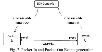
Packet-Out. Packet_In event raise from a switch and the controller subscribe the event through its event handler. The Packet-In event is raised when a switch gets a packet and do not have any match entry in its flow table and thus forward the packet to the controller. Conversely the event Packet-Out will rise when a controller wants to send messages to switches. Switch will receives message from controller through Packet-Out event. There is a link layer protocol called Link Layer Discovery Protocol (LLDP) for advertising identity, capabilities and neighbor of a network. Two events Packet-In, Packet-Out and Link Layer Discovery Protocol (LLDP) are needed to discover links in a network.
In Fig. 2, switch Si gets a LLDP packet via Packet-Out
event from the controller. Switch Si then flood the received
LLDP packet to all its ports except ingress port. Switch S2
receives the LLDP packet from switch S1 through its port j.
Then switch S2 forwards the LLDP packet to the controller via
Packet-In event. From the contents of LLDP packet, controller come to know the link between (S1, Port i) & (S2, Port j). This
process of link finding continues for all the switches exist in a network. Algorithm 2 is an application for the controller to send LLDP packets to every switch and receives all returned LLDP packets from switches. All discovered links are saved in adjacency table(A).
Algorithm 2: Generate and process LLDP-packet at controller
Output: Adjacency Table (A) {
Forall Switch 𝑆𝑖 𝑖𝑛 𝑆 do
Send LLDP-packet via Packet-Out event to switch
𝑆𝑖 from Controller
Forall received LLDP-packet via Packet-in event do
Insert Link of Si & Sj in A with
𝐴 𝑖, 𝑗 = (𝑃𝑜𝑟𝑡𝑖 , 𝑃𝑜𝑟𝑡𝑗)
where 𝑃𝑜𝑟𝑡𝑖 ∈ 𝑃𝑖 & 𝑃𝑜𝑟𝑡𝑗 ∈ 𝑃𝑗
}
Algorithm 3: Forward LLDP-Packet at switch.
{
Forall incoming LLDP-Packet do If LLDP-Packet.inPort = Controller then
Flood LLDP-Packet to all ports except ingress port
Else
Send LLDP-Packet to the Controller Via Packet-In event
}
Fig. 2. Packet-In and Packet-Out Events generation
[image:2.612.45.297.500.589.2]Si Pi1 Mi1 Pi2 Mi2 Pi3 Mi3 Pi4 Mi4 … Pin Min
Algorithm 3 is a task for every switch. All switches will accept all LLDP packets and floods if the sender is controller (except ingress port) else forward it to the controller via Packet-In event as shown in Fig 2.
Let us take an example of a network in Fig 3. After discovering of all links using Algorithm 2 & Algorithm 3, the contents of adjacency table (A) shown in Table 2.
A value Si, Sj = (Porti,Portj) means Si is connected to Sj
via the Porti and Portj, where Porti ∈ Pi & Portj ∈ Pj.
Assume the structure of the network shown is in fig 3.
The next step is to find a path between every switch to every other switch in a network. Algorithm 4 finds path to every switch to every other switches and it also identify list of loops in a topology. This list of loops will help in finding alternative paths during link failure.
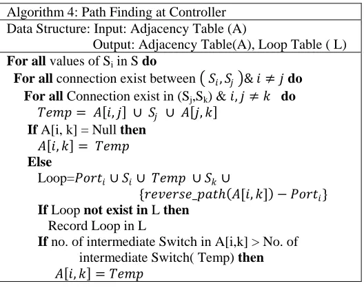
Algorithm 4: Path Finding at Controller Data Structure: Input: Adjacency Table (A)
Output: Adjacency Table(A), Loop Table ( L)
For all values of Si in S do
For all connection exist between 𝑆𝑖, 𝑆𝑗 & 𝑖 ≠ 𝑗do
For all Connection exist in (Sj,Sk) & 𝑖, 𝑗 ≠ 𝑘 do
𝑇𝑒𝑚𝑝 = 𝐴 𝑖, 𝑗 ∪ 𝑆𝑗 ∪ 𝐴 𝑗, 𝑘
If A[i, k] = Null then
𝐴 𝑖, 𝑘 = 𝑇𝑒𝑚𝑝
Else
Loop=𝑃𝑜𝑟𝑡𝑖∪ 𝑆𝑖∪ 𝑇𝑒𝑚𝑝 ∪ 𝑆𝑘∪
{𝑟𝑒𝑣𝑒𝑟𝑠𝑒_𝑝𝑎𝑡ℎ 𝐴[𝑖, 𝑘] − 𝑃𝑜𝑟𝑡𝑖}
If Loop not exist in L then
Record Loop in L
If no. of intermediate Switch in A[i,k] > No. of intermediate Switch( Temp) then 𝐴 𝑖, 𝑘 = 𝑇𝑒𝑚𝑝
Let us take an example, how Algorithm 4 works for the network in Fig. 3.
Pass 1: For Si=S1, Sj=S2, Sk=S5,
𝐴 1,5 = 𝐴 1,2 ∪ 𝑆2 ∪ 𝐴 2,5
= 𝑃2, 𝑃1∪ 𝑆2 ∪ 𝑃2𝑃2
= 𝑃2, 𝑃1𝑆2𝑃2, 𝑃2
New entry: (S1, S5) = P2, P1S2P2, P2
After pass 1, the content of adjacency table (A) is shown in Table 3.
Pass 2: For Si=S1, Sj=S3, Sk=S4,
1 2 3 3 1 1 2 3 3 1 3 , , , , ] 4 , 3 [ ] 3 , 1 [ ] 4 , 1 [ P P S P P P P S P P A S A A
New entry (S1, S4) =P1, P1S3P2, P1andtheadjacency table’s (A) content shown in Table 4.
Pass 03: For Si=S1, Sj=S4, Sk=S5,
Similarly if we continue pass 03 steps for Algorithm 4, we get
1 , 2 4 1 , 2 3 1 , 1 1 , 2 4 1 , 2 3 1 , 1 ] 5 , 4 [ 4 ] 4 , 1 [ P P S P P S P P P P S P P S P P A S A Temp
Since the content of A[1,5] is not null, means there is a presence of loop between S1 to S5.
1 2 2 , 2 5 1 , 2 4 1 , 2 3 1 , 1 1 2 } 2 ) 2 , 1 2 2 , 2 {( 5 1 , 2 4 1 , 2 3 1 , 1 1 2 } 2 ) 2 , 2 2 1 , 2 ( _ { 5 1 , 2 4 1 , 2 3 1 , 1 1 2 } 1 ]) 5 , 1 [ ( _ { 5 1 1 Port P S P P S P P S P P S P P S P P P P S P P S P P S P P S P P S P P P P S P P path reverse S P P S P P S P P S P Port A path reverse S Temp S Loop
The value of loop is identified and placed in loop table as shown in Table 6. Again path (P1,P1S3P2,P1S4P2,P1) contains
two intermediate switch S3 & S4 and the path (P2, P1S2P2, P2)
contain one intermediate switch S2. Here we use least
intermediate node path, hence the value of (S1,S5) in adjacency
[image:3.612.314.569.51.474.2]table is (P2, P1S2P2, P2). After Pass 03, the adjacency table(A) is shown in Table 5.
TABLE 4
ADJACENCY TABLE(A) AFTER PASS2
S1 S2 S3 S4 S5
S1 - P2,P1 P1,P1 P1, P1S3P2, P1 P2,P1S2P2,P2
S2 P1,P2 - - - P2, P2
S3 P1,P1 - - P2, P1 -
S4 - - P1,P2 - P2, P1
S5 P2,P2 P1, P2 -
TABLE 3
ADJACENCY TABLE(A) AFTER PASS 1
S1 S2 S3 S4 S5
S1 - P2,P1 P1,P1 - P2, P1S2P2, P2
S2 P1,P2 - - - P2, P2
S3 P1, P1 - - P2, P1 -
S4 - - P1,P2 - P2, P1
[image:3.612.65.285.150.264.2]S5 P2, P2 P1, P2 -
[image:3.612.53.292.338.415.2]Fig. 3. Network contains five OpenvSwitch (S1,S2,S3,S4 & S5)
TABLE 2
ADJACENCY TABLE( A) OF SWITCH-TO-SWITCH CONNECTION
S1 S2 S3 S4 S5
S1 - P2, P1 P1,P1 - -
S2 P1,P2 - - - P2, P2
S3 P1, P1 - - P2, P1 -
S4 - - P1,P2 - P2, P1
[image:3.612.319.567.354.462.2] [image:3.612.42.306.512.721.2]If we continue our steps, the final adjacency table is shown in Table 7 and Loop table will be same as shown in Table 6.
IV. ROUTING AND FAILURE RECOVERY USING ADJACENCY MATRIX TABLE & LOOP TABLE
Let us take a machine Mi attached to switch Si wants to
communicate with the machine Mj attached to switch Sj. When
packets from Mi arrived at switch Si, switch Si searches the
flow match for the destination address Mj in its flow table. At
initial condition, there is no flow entry in its flow tables in switch Si for the destination machine Mj and therefore
forwarded to the controller via Packet-In event. From the IPaddress Map Table(𝑆𝑖 → 𝑃𝑖𝑗𝑀𝑖𝑗), controller get the DPID and port number of destination switch for Mj. The
communication path between source switch to destination switch can get from adjacency table (A). Finally controller instructs flow entry for every switch from Si to Sj via
Packet-Out event.
For instance, path between S1 to S5 is S1P2→P1S2P2→P2S5.
The meaning of S1P1 is P2 is the egress port of S1 switch and
the meaning of P2S5 is P2 ingress port of S5. In addition, the
intermediate switch S2 has ingress port P1 & egress port P2.
Controller give flow entry for switch S1,S2 and S5 for the
communication between Mi to Mj. All packets for the said
communication will follow the path S1→S2→S5.
Now assume, link Si→Sj goes down. The controller comes
to know that the link (Si,Si) is down via PortStatus event raised
from the switches Si & Sj. Henceforth the controller need to
find alternate path for the link (Si,Si). For such case, the loop
table (L) will helps for alternative path. Controller first searches a loop contained both switches Si & Sj in loop table
(L). If there is a loop available, then alternate path can get from loop by reading it in the reverse direction from Si to Sj
and converts all ingress port to egree port & vice versa for all switches Si to Sj. The same is shown in Fig. 4. The changes are
updated in its adjacency table (A) and in loop table (L).
Algorithm 5: Alternate path at Controller Data Structure:
Input: Down Link (𝑆𝑖, 𝑆𝑗)
Loop Table ( L)
Output: Alternate_Path of down Link (𝑆𝑖, 𝑆𝑗)
For all loop in L do
if loop contained edge (𝑆𝑖, 𝑆𝑗)then
𝑇𝑒𝑚𝑝 = 𝑅𝑒𝑣𝑒𝑟𝑠𝑒_𝑅𝑒𝑎𝑑_𝑃𝑎𝑡ℎ(𝑙𝑜𝑜𝑝 𝑓𝑟𝑜𝑚 𝑆𝑖 𝑡𝑜𝑆𝑗)
forall value Si in Sdo
forall value Sj in S and 𝑖 ≠ 𝑗 do
if A[i,j] path contain edge (Si, Sj) then
Replace (Si,Sj) in A[i,j] with Temp as below
𝐴 𝑖, 𝑗 = 𝑃𝑎𝑡ℎ (𝑃𝑖… 𝑇𝑒𝑚𝑝 … 𝑃𝑗) Delete Entry L in loop
Algorithm 5 shows to find an alternative path during any link down. Assume, Pm′SmPm, … … Pi′SiPi, Pj′SjPj, … … , Pn′SnPn be a
loop contain both (Si,Si). So, the Reverse_Read_Path will be PiSiPii… … PmSmPm′, PnSnPn′, … … PjSjPj′
For instance,
Assume down Link: (S3,S4).
Loop contained (S3,S4) link inL is, P2S1P1, 𝐏𝟏𝐒𝟑𝐏𝟐, 𝐏𝟏𝐒𝟒𝐏𝟐, P1S5P2,P2S2P1
Earlier value of A[1,4]= P1, P1S3P2, P1
Temp= Reverse_Read_Path(L from S3 to S4)
= 𝑃2𝑆3𝑃1,𝑃1𝑆1𝑃2, 𝑃1𝑆2𝑃2, 𝑃2𝑆5𝑃1, 𝑃2𝑆4𝑃1
New Entry A[1,4]= Path( S1P1, Temp, P1S4)
=Path( S1P1, P2S3P1,P1S1P2, P1S2P2, P2S5P1, P2S4P1, P1S4)
= (S1P2, P1S2P2, P2S5P1, P2S4)
[image:4.612.331.529.52.135.2]=(P2, P1S2P2, P2S5P1, P2)
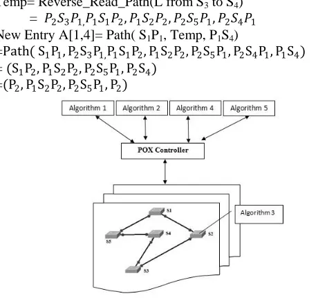
Fig.5. The network architecture with POX controller and its applications
[image:4.612.51.303.54.186.2]Fig. 4. Alternative path after down link (S3 to S4)
TABLE 7
ADJACENCY TABLE(A) AFTER ALL PASS COMPLETED
S1 S2 S3 S4 S5
S1 - P2, P1 P1,P1 P1,P1S3P2,P1 P2,P1S2P2 ,P2
S2 P1,P2 - P1,
P2S1P1, P1
P2,P2S5P1,P2 P2, P2
S3 P1,P1 P1,P1S1P2 ,P1
- P2, P1 P2,P1S4P2 ,P1
S4 P1,P2S3P1 ,P1
P2,P1S5P2 , P2
P1,P2 - P2, P1
S5 P2,P2S2P1 ,P2
P2, P2 P1, P2S4P1,P2
P1, P2 - TABLE 6
LOOP TABLE AFTER PASS 04
Index Loop
1 P2S1P1, P1S3P2, P1S4P2, P1S5P2,P2S2P1
TABLE 5
ADJACENCY TABLE(A) AFTER PASS 04
S1 S2 S3 S4 S5
S1 - P2,P1 P1,P1 P1, P1S3P2, P1 P2, P1S2P2, P2
S2 P1,P2 - - - P2, P2
S3 P1,P1 - - P2, P1 -
S4 - - P1,P2 - P2, P1
[image:4.612.49.296.64.310.2] [image:4.612.50.300.227.346.2] [image:4.612.317.547.482.698.2]We used here POX controller as SDN controller and mininet emulator as network infrastructure respectively. Network architecture and placement of different algorithms are shown in Fig. 5.
V. CONCLUSION
For any SDN architecture, topology discovery is an important issue. The proposed algorithms are work as event handler for the controller. We maintained adjacency table and loop table to find path and alternative paths. We used minimum intermediate node path for communication. Our next plan is to design north bound applications for energy efficient resource control, load balancing and traffic engineering in SDN paradigm.
REFERENCES
[1] Nunes, B.A.A.; Mendonca, M.; Xuan-Nam Nguyen; Obraczka, K.; Turletti, T., "A Survey of Software-Defined Networking: Past, Present, and Future of Programmable Networks," Communications Surveys &
Tutorials, IEEE , vol.16, no.3, pp.1617,1634, Third Quarter 2014
[2] Kreutz, D.; Ramos, F.M.V.; Esteves Verissimo, P.; Esteve Rothenberg, C.; Azodolmolky, S.; Uhlig, S., "Software-Defined Networking: A Comprehensive Survey," Proceedings of the IEEE , vol.103, no.1, pp.14,76, Jan. 2015
[3] Jarraya, Y.; Madi, T.; Debbabi, M., "A Survey and a Layered Taxonomy of Software-Defined Networking," Communications Surveys &
Tutorials, IEEE , vol.16, no.4, pp.1955,1980, Fourthquarter 2014
[4] Fei Hu; Qi Hao; Ke Bao, "A Survey on Software-Defined Network and OpenFlow: From Concept to Implementation," Communications Surveys & Tutorials, IEEE , vol.16, no.4, pp.2181,2206, Fourthquarter 2014 [5] Msahli, M.; Pujolle, G.; Serhrouchni, A.; Fadlallah, A.; Guenane, F.,
"Openflow and on demand networks," Network of the Future (NOF), 2012 Third International Conference on the , vol., no., pp.1,5, 21-23 Nov. 2012
[6] Giroire, F.; Moulierac, J.; Phan, T.K., "Optimizing rule placement in software-defined networks for energy-aware routing," Global
Communications Conference (GLOBECOM), 2014 IEEE , vol., no.,
pp.2523,2529, 8-12 Dec. 2014
[7] Carpa, Radu; Gluck, Olivier; Lefevre, Laurent, "Segment routing based traffic engineering for energy efficient backbone networks," Advanced Networks and Telecommuncations Systems (ANTS), 2014 IEEE
International Conference on , vol., no., pp.1,6, 14-17 Dec. 2014
[8] Jianchao Zhang; Boon-Chong Seet; Tek-Tjing Lie; Chuan Heng Foh, "Opportunities for Software-Defined Networking in Smart Grid," Information, Communications and Signal Processing (ICICS) 2013 9th International Conference on , vol., no., pp.1,5, 10-13 Dec. 2013
[9] Khondoker, R.; Zaalouk, A.; Marx, R.; Bayarou, K., "Feature-based comparison and selection of Software Defined Networking (SDN) controllers," Computer Applications and Information Systems
(WCCAIS), 2014 World Congress on , vol., no., pp.1,7, 17-19 Jan. 2014
[10] Jmal, R.; Chaari Fourati, L., "Implementing shortest path routing mechanism using Openflow POX controller," Networks, Computers and Communications, The 2014 International Symposium on , vol., no., pp.1,6, 17-19 June 2014
[11] Pakzad, F.; Portmann, M.; Wee Lum Tan; Indulska, J., "Efficient topology discovery in software defined networks," Signal Processing and Communication Systems (ICSPCS), 2014 8th International Conference on , vol., no., pp.1,8, 15-17 Dec. 2014
[12] Sharma, S.; Staessens, D.; Colle, D.; Pickavet, M.; Demeester, P., "Fast failure recovery for in-band OpenFlow networks," Design of Reliable
Communication Networks (DRCN), 2013 9th International Conference
on the , vol., no., pp.52,59, 4-7 March 2013
[13] Sharma, S.; Staessens, D.; Colle, D.; Pickavet, M.; Demeester, P., "Enabling fast failure recovery in OpenFlow networks," Design of
Reliable Communication Networks (DRCN), 2011 8th International