Abstract— The paper concerns the strengthening using FRP composites of masonry walls loaded in the plane. Strength of unreinforced masonry walls is based on the strength of mortar and bricks proportions and layout. When the force reaches a sufficient value to exceed the in-plane strength of the wall, the destruction can occur due to shear. This failure is characterized by different factors: diagonal tension, joint sliding and flexural cracking. The paper presents an analytical model and numerical calculations for two different systems of FRP strips. FRP strips were installed parallel to the bed and head layer of mortar and along the diagonals of the wall in the X-shaped form. In the recent years, interest in the renovation of the construction and strengthening of existing masonry buildings has led to the development of non-invasive methods of engineering. As an alternative to the use of traditional methods advanced FRP composite fiber can be used. FRP strips offer perfect physical and mechanical properties. The main characteristics of the composite FRP are little effect on the overall structure weight, high tensile strength (ultimate and long-term) in the fiber direction and negligible in the direction transverse to them. Their function is primarily to take over the tensile stresses caused by the action of shear and bending. Achievable advantages of their use are also increasing of the total stiffness, ductility, flexibility (very high value of limit strains), high corrosion resistance, easy way of application in areas with limited access, no need for application of heavy equipment when working with composite materials, and fast installation. Furthermore, the use of FRP composites can be the perfect solution for modernization of structural walls in seismic areas, and gives effectiveness in repairing damaged masonry structures during the earthquake.
Index Terms— in-plane behavior, masonry walls, strengthening, FRP composite
I. INTRODUCTION
In the recent years the importance of the repair and strengthening of masonry structures has greatly increased. This is due not only to the destruction of masonry structures as a result of natural disasters, but also because many of the typical masonry structures have achieved their service life, and as well it is a result of a many activities in the revitalization design. Masonry structures can be damaged due to the low strength of the construction or overloading, dynamic vibration, settlement and in-plane deformation. Behavior of masonry walls loaded in their plane depends on various parameters, such as mechanical and geometrical
Manuscript received February 21, 2014; revised April 01, 2014. J. Szolomicki is with the Institute of Building Engineering, Wroclaw University of Technology, Wroclaw, POLAND (e-mail: jerzy.szolomicki@ pwr.edu.pl).
properties, load schema and boundary conditions. Strength of unreinforced masonry walls is based on the strength of mortar and bricks proportions and layout. When the force reaches a sufficient value to exceed the in-plane strength of the wall, the destruction can occur due to shear. This type of failure is characterized by brittle tensile cracking in mortar and brick, and sudden loss of lateral resistance.
The traditional methods used in the repair of masonry are: - filling cavities, internal voids and sealing possible cracks
using injection of mortar or fluid resin;
- stitching of large cracks and other weak areas by drilled holes in the element filled with bars and mortar;
- use of reinforced grouted perforations in order to improve the consistency and tensile strength of the wall;
- external jacketing using shotcrete or cast-in-situ concrete; - internal or external post-tensioning with steel ties in order
to tie structural elements together into an integrated three-dimensional system.
Conventional techniques of strengthening can ensure adequate increase of strength, stiffness and ductility, but are often short-lasting and have extensive influence. Moreover, additional components can be installed to transfer additional forces or to strengthen existing braces and struts. As an alternative to these solutions, in the event of a significant increase in the load of strengthened structures composite materials may be used [5].
The composite materials are made of polymeric fibers with high strength and are impregnated with polymeric resins. FRP composites are characterized by perfect tensile strength in the fiber direction and the low strength in the direction transverse to the fibers [12]. Their main function is to adsorb the tensile stresses arising from shear and bending. Among the achievable advantages there are also overall stiffness, strength and ductility.
The fibers most used for composite materials employed in the applications for the civil engineering structures are: carbon CFRP and glass GFRP [1]. The most common shape of the composite materials is the laminate one. The laminates are constituted by two or more overlapped thin layers [3], [14]. The fibers provide the strength and the resin matrix holds them in place and transfers the load evenly amongst the fibers. The resin also protects the fibers and bonds them to the surface, transferring the load from the structure into the fibers.
Methods of strengthening using CFRP and GFRP composite materials positively affect the bearing capacity and the response of the structure [7]. FRP composites are important in the transferring of load, compensating the lack of tensile strength of masonry structures [4]. However,
Computer Analysis of In-plane Behavior
of Masonry Walls Strengthened by FRP Strips
different types of fibres (CFRP and GFRP ones [8, 13, 15]) and placing the reinforcement in different positions, and to formulate analytical models able to predict the ultimate strength in agreement with the observed failure mechanisms. The application of FRP strips modifies the static behavior of walls because the fibres can bear the stresses occurring at the tensed edges.
II. MODEL OF FRP AND MASONRY
Design of FRP strips reinforcement should ensure that the system is always in tension. Compression of FRP composite may cause debonding due to local instability. FRP composites are generally used in masonry walls in different geometrical arrangements. In presented numerical analysis two different pattern of wall strengthening were used: - wall strengthened with cross pattern Carbon and Glass
FRP strips;
- wall strengthened with grid pattern Carbon and Glass FRP strips.
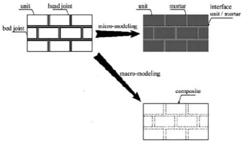
[image:2.595.303.551.50.196.2]In recent decades, many authors have proposed different strategies for determining the numerical modeling of the structural response of masonry structures [10]. For example taken into account the heterogeneity of the wall consisting of blocks connected by a head and bed mortar. There can be indicated the three concepts of numerical modeling of the wall. The first one is called the micro-modeling or two-material model, the second simplify micro-modeling, and the third is referred to as macro-modeling or equivalent material model, Fig. 1. This last approach, also known as homogenization, requires the adoption of a unified representative replacement cell, which is a simplification of the real system components forming the wall. Its parameters must correspond to the most of the actual parameters of the material, which is the basis of the effectiveness of the application of the FEM. In computer analysis of the walls was used the homogenized anisotropic numerical model proposed by Lopez [9]. This model is based on assumptions about the compatibility of deformation and equilibrium model of representative homogenized masonry cell, Fig. 2.
Fig. 1. Micro and macro-model of masonry structures.
The in-plane resistance in load-bearing unreinforced masonry walls is provided by the shear bond strength of the mortar and the friction shear due to the horizontal load. The shear strength of a bearing wall, in the case of a sliding failure mode, can be determined as:
(1) where:
- shear stress at the shear bond failure, - shear bond strength at zero normal stress due to adhesive strength of a mortar, - coefficient of friction between brick and mortar,
- normal stress.
FRP composites can provide viable solutions for strengthening of walls subjected to stresses caused by wind or earthquake loads.
Fig. 2. Base cell of representative homogenized masonry.
III. MODEL OF FINITEELEMENTMETHOD In the presented paper the studied models were analyzed using FE analysis using the LUSAS code, ver. 14.7. Masonry wall was modeled by means of the solid elements HX 16 and HX 20, Fig. 3. As the constitutive model for masonry material a homogenized model was applied as proposed by Lopez et al [9].
[image:2.595.304.544.412.553.2]Fig. 3. Examples of applied solid elements [11].
IV. NUMERICAL ANALYSIS OF MASONRY WALLS STRENGTHENED WITH FRP STRIPS
Carbon fiber reinforced polymers (CFRP) and glass fiber reinforced polymers (GFRP) were considered for investigating the behavior of FRP strips bonded on masonry walls.
Fig. 4. Geometry, loading and boundary conditions of analyzed masonry wall.
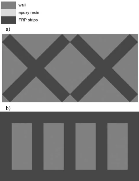
The walls with dimensions (2.40 m x 1.2 m x 0.25 m) and with loading conditions shown in Fig. 4 were the subject of the analysis. Numerical analysis was completed taking into account literature data [2] which indicated the location and the layout of the strengthening strips as in Fig. 5.
In order to compare the validity of the proposed computer modeling technology and behavior of not strengthened and strengthened walls up to the ultimate state the following cases were investigated:
- wall without strengthening;
- wall strengthened with cross pattern by using CFRP (epoxy TB650+HS Carbon UD) (Tab. 1);
- wall strengthened with cross pattern by using GFRP (epoxy TB650+E-Glass) (Tab. 1);
- wall strengthened with grid pattern by using CFRP (epoxy TB650+HS Carbon UD) (Tab. 1);
- wall strengthened with grid pattern by using GFRP (epoxy TB650+ E-Glass) (Tab. 1).
Numerically examined walls were strengthened before failure mode was reached.
a)
b)
Fig. 5. Different types of application of FRP strips for wall strenghtening: a) wall strengthened with cross pattern, b) wall strengthened with grid pattern.
TABLEI
BASIC CHARACTERISTICS OF CFRP AND GFRP STRIPS [11] Strips Widt
h (cm)
Thicknes s (mm)
Modulu s Ex (N/m2)
Modulu s Ey (N/m2)
Modulu s Gxy (N/m2)
CFRP 20 2 130.0E9 9.0E9 4.4E9
GFRP 20 2 43.0E9 8.0E9 4.0E9
Each model was studied considering typical horizontal uniformly distributed load cases (Fig. 4).
Selected results of stress distribution calculations were presented in the figures below:
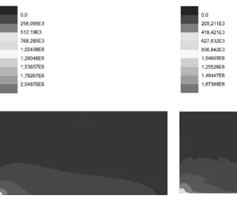
- stress S1 in not strengthened masonry wall for horizontal uniformly distributed load 200 kN/m2 (Fig. 6);
- stress S1 in wall strengthened with cross pattern by using CFRP strips for horizontal uniformly distributed load 200 kN/m2 (Fig. 7);
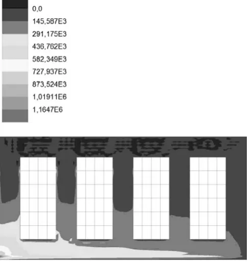
- stress S1 in wall strengthened with grid pattern by using CFRP strips for horizontal uniformly distributed load 200 kN/m2 (Fig. 8);
- stress S1 in cross pattern of CFRP strips for horizontal uniformly distributed load 200 kN/m2, 500 kN/m2 (Fig. 9, 10);
[image:3.595.54.269.56.175.2]Fig. 6. Stress S1 in not strengthened masonry wall for horizontal uniformly distributed load 200 kN/m2.
Fig. 7. Stress S1 in masonry wall strengthened with cross pattern by using CFRP strips for horizontal uniformly distributed load 200 kN/m2.
From Figs 6 to 12 it is possible to see that CFRP and GFRP strips transferred exceeded tensile stresses and significantly reduced it in the wall.
[image:4.595.304.546.376.653.2]Fig. 8. Stress S1 in masonry wall strengthened with grid pattern by using CFRP strips for horizontal uniformly distributed load 200 kN/m2.
[image:4.595.307.549.520.650.2]Fig. 10. Stress S1 in cross pattern of CFRP strips for horizontal uniformly distributed load 500 kN/m2.
[image:5.595.153.533.51.317.2]Fig. 11. Stress S1 in grid pattern of CFRP strips for horizontal uniformly distributed load 200 kN/m2.
Fig. 12. Stress S1 in grid pattern of CFRP strips for horizontal uniformly distributed load 500 kN/m2.
V. CONCLUSIONS
The objective of the presented study was to determine the behavior of unreinforced and FRP strengthened masonry walls under in-plane loading. For this purpose, the numerical approach was carried out.
In-plane load of the examined wall was assumed in order to observe the behavior of the wall from the initial state (not damaged one) to the state of its destruction. For such model stress distribution analyses in the wall without reinforcement and in the walls strengthened with CFRP and GFRP strips (grid and cross pattern) were conducted. For the walls strengthened with CFRP and GFRP strips it can be clearly seen that the tensile stresses are transferred to these stripes that leads to a significant reduction of theses stress in the masonry wall. As the load increases, the zone of maximum tensile stress occurs in the lower corner of the wall and moves up. Tensile stress in the wall without reinforcement causes appearance of cracks and with their further increase cause destruction. In the case of walls strengthened with CFRP and GFRP fibres stress S1 distribution is similar. When the load increases installed FRP strips transfer greater tensile stresses. However, it should be noted, that more efficient for the transfer of unfavorable tensile stress in the case of cross pattern are the CFRP strips then GRFP ones.
[image:5.595.48.291.373.631.2][4] S. W. Chuang, Y. Zhuge, T. Y. Wong, L. Peters, “Seismic retrofitting of unreinforced masonry walls by FRP strips”, Proceedings of Pacific
Conference on Earthquake Engineering, 2003.
[5] P. Foster, J. Gergely, D. Young, M. McGinley, “Strengthening masonry buildings with FRP composites”, Proceedings of the 11th
International Conference: Structural Faults & Repair, Edinburgh,
UK, 183 (2006) [CD-ROM version].
[6] E. Garbin, M. R. Valluzzi, C. Modena, N. Galati, A. Nanni, “In-plane design for masonry walls strengthened by FRP materials”, Proceedings of the 11th International Conference: Structural Faults
& Repair, Edinburgh, UK, 184 (2006) [CD-ROM version].
[7] R. M. Kiss, L. P. Kollar, J. Jai, H. Krawinkler, “Masonry strengthened with FRP subjected to combined bending and compression, Part II: Test results and model predictions”, Journal of
Composite Materials, 36(9),2002, pp. 1049-1063.
[8] Y. Liu, J. Dawe, J. McInerney, “Behaviour of GFRP sheets bonded to masonry walls”, Proceedings of the International Symposium on Bond
Behaviour of FRP in Structures(BBFS), Hong Kong, China, 2005,
pp. 473-480.
[9] J. Lopez, S. Oller, E. Onate, J. Lubliner, “A homogeneous constitutive model for masonry”, International Journal for Numerical Methods in
Engineering, 46, 1999.
[10] P.B. Lourenco, “Experimental and numerical issues in the modeling of the mechanical behavior of masonry”. II Structural Analysis of
Historical Constructions (IISAHC) – Barcelona, 1998.
[11] Lusas Version 14.7, Element Reference Manual, Lusas, 2011, UK. [12] A. Morbin, “Strengthening of Masonry Elements with FRP
Composites”. University of Missouri-Rolla, pp. 192.
[13] A. Nanni, G. Tumialan, “Fiber-reinforced composites for the strengthening of masonry structures”, Structural Engineering
International, 13(4), 2003, pp. 271-278.
[14] M. Panizza, E. Garbin, M. R. Valluzzi, C. Modena, “Bond behaviour of CFRP and GFRP laminates on brick masonry”, Proceedings of the 6th International Conference on Structural Analysis of Historical
Construction, Bath, UK, 2008, pp. 763-770.
[15] M. R. Valluzzi, “Strengthening of masonry structures with Fibre Reinforced Plastics: From modern conception to historical building preservation”, Proceedings of the 6th International Conference on
Structural Analysis of Historical Construction, Bath, UK, 2008, pp.