Abstract—This paper investigates the crush characteristic of foam filled tubes under quasi-static axial load. The specimens are circular steel and aluminum tubes. The tubes are filled with PU foam with densities of 100 and 200 kg/m3. The
specimens are crushed under quasi-static compression with a speed of 50 mm/min. Computer simulation is also conducted and the result is compared with experiment, good agreement is achieved. This study reveals that filling foam in tube affects the mode of collapse of tubes significantly. The mode of collapse of aluminum tube is changed from diamond mode or mix mode to be concertina mode when the tube is filled with PU foam. In contrast, collapse mode of steel tube is changing from concertina mode to be mix mode when it is filled with foam. It is also found that filling foam in tube can enhance the energy absorption capacity of tube as the energy absorptions of foam filled tubes are higher than those of empty tubes. However, the specific energy absorption seems to be decreased as the density of foam is increasing.
Index Terms—metal tube, energy absorption, axial load, foam-filled tube
I. INTRODUCTION
Metals, such as steel and aluminum, have been widely used in many engineering structures i.e. automobile, aircraft, piping and machineries. This is because metal can be formed in various shapes and joined by many techniques. Focusing on automotive industry, metal can be considered as the main material for car body due to its crashworthiness characteristic. Normally, the car body is designed to be able to be collapsed and absorbs impact energy. However, the collapse must be controlled and limited in the position which no harm to passengers in the cockpit. Therefore, many researchers have been attempting to improve energy absorption capacity of automotive body using many techniques. The study focusing on shape and geometric parameters of structure, type of materials i.e. composite, hybrid and inserting materials are some topics of research in this area. Dong-Kuk Kim et. al. [1] studied on the crashworthiness of square and circular tube with thickness of1.2mm, 2.0 mm and 3.0 mm. The thickness to width ratio
Manuscript received March 18, 2016.
Thinvongpituk C. is with the Department of Mechanical Engieering, Faculty of Engineering, Ubon Ratchathani University, Warinchamrab, Ubonratchathani, Thailand, 34190, phone: +0066 45 353309 fax: +0066 45 353308; e-mail: [email protected]
Onsalung N. is with Division of Mechanical Engineering, Faculty of Industry and Technology, Rajamangala University of Technology Isan, Phangkhon, Sakon-Nakhon, Thailand 47160, phone: +0066 042 772 391, Fax: +0066 042 772 392, e-mail: [email protected]
Poonaya S. is with the Department of Mechanical Engieering, Faculty of Engineering, Ubon Ratchathani University, Warinchamrab, Ubonratchathani, Thailand, 34190, phone: +0066 45 353309 fax: +0066 45 353308; e-mail: [email protected]
(t/W) and thickness to diameter ratio (t/D) were varied. The result suggested that the symmetric mode is occurred in high t/W for square tube and in low t/D for circular tube. In the same year, Langseth et al. [2], [3] investigated the energy absorption capacity of rectangular tube under static and dynamic load using LS-DYNA and compared to experiment. They focused on the influence of mass and impact speed of impactor. This result was also compared with the results of Nia [4] and Yamasita [5] as well as Gupta [6]. The results suggested that symmetric mode usually delivers higher energy absorption value. Therefore, mechanism to control collapse mode to gain symmetric mode is attractive to some investigators. There are many techniques to get symmetric mode, one of those is filling plastic foam in the structure. Furthermore, filling foam also helps improving energy absorption without increasing too much weight. P. Raju Mantena and Richa Mann [7] investigated the circular foam filled tube under impact. Different densities of foam were filled in tubes. The experimental result was compared to FEA result which was conducted with ABAQUS. The result indicated that filling foam in tube can improve energy absorption of structures.
It is worth to mention here that there are many types of foam used to fill in the structure. Some examples are metallic foam, polymeric foams such as aluminum foam, [8]-[10] polystyrene foam [11]-[12], PVC foam [13] and polyurethane foam [14]-[15]. Among those, polyurethane foam or PU foam is quite interesting due to it is cheap and widely used in some engineering purposes such as container, insulator or wire arrangement in some parts of vehicles. Recently, there have been some researchers studied on PU foam as energy absorption improvement device. Some research reported that filling PU foam in tube could change collapse mode from asymmetric mode to axisymmetric mode [16]-[17]. C.J. Zhang [18] found that the interaction between PU foam surface and tube wall increases the total energy absorption of structure. Normally, filling foam technique is used in aluminum rather than steel tubes because aluminum tube is lighter and the effect of foam is prominent. However, both aluminum and steel are widely used in vehicle structures, therefore, the comparative study for both materials are interesting.
This paper is aimed to study the energy absorption capacity of foam filled circular tubes made from aluminum and steel. The influence of foam density and geometric ratio are focused. Energy absorption behavior and collapse mode of them are investigated and discussed.
II. METHODOLOGY A. Parameters Definition
The crashworthiness parameters can be considering from load-displacement curve. The energy absorption of a structure can be approximated by Eq. (1). The structure
Crush Characteristic of Foam-Filled Circular
Steel and Aluminum Tubes under Axial Loading
under axial crushing load should be high energy absorption when compared to the mass of the device. This concerned is reflected in specific energy absorption which is an important criterion for lightweight design. Generally, only the crushed mass of an absorber is taken into account. However, in some complex structures which the crushed mass is difficult to measure, the total mass of the structure may be used. This parameter is obtained by dividing the energy absorption by mass as shown in Eq. (2).
mean
0 .
S
a
E
PdSP S (1)s a/
E E mass (2)
Where S is the crushing stroke of a deformed specimen, P and Pmean is the instantaneous crushing load and average
crushing load respectively, and mass is the total mass of tube and foam.
B. Material and properties
Polyurethane foam
The light weight material that used in this study is polyurethane (PU) foam. Polyurethane foam can be produced by mixing together of two chemicals, namely IsocyanateandPolyol. Both substances are mixed in a ratio of 1:1 in liquid form. As a result, the volume of foam increases up to 27 times. Normally, the density of foam variesfrom 30 to 40kg/m3. The thermal conductivityis low that makes rigid polyurethane foam an excellent insulator. Polyurethane ischaracterized bytremendous amount of air bubbles foaming closed cells which trap air inside. It is resistant to impact weather of all seasons. The mechanical properties of the PU foam are tested under axial compression loading. Before compression test, the polyurethane foam is produced in cubic shape with about 50mm × 50mm × 50 mm and then tested by uniaxial compressive at constant speed of 5 mm/min. Afterwards the true stress and plastic strain will be calculated from this curve in order to specify the plastic deformation data. This parameter is required in the finite element simulation. Specimen Preparation
The empty and foam-filled specimen in the study are made of aluminum alloy (AA6063-T5) and mild steel (AISI 1020). The circular tubes with three different value of D/t ratio are applied in the present study. They are 21.17, 33.87, and 42.33. Each D/t ratios are consisting of the empty and foam-filled tube which varies the density of PU foam, e.g. 100 kg/m3 and 200 kg/m3.
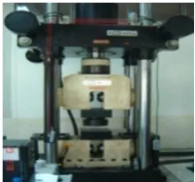
Initial high of specimens before filling with polyurethane foam is 200 mm height. After filled with polyurethane foam, the tubes are cut at both ends to have 150 mm height. The specimens are made in triplicate in order to repeat the test. The ESH universal testing machine with 2,000 kN capacity is applied. The typical specimens of foam-filled tube are shown in Fig. 1.
In order to gain the property of tube, the specimens are cut along the axial direction and using standard test methods for tension testing of metallic materials (ASTM E8M). In order to identify the property, the specimens are sent to the National Metal and Materials Technology Center (MTEC), National Science and Technology Development Agency (NSTDA) for tensile testing. In this study, the steel tube is low carbon steel AISI 1012 whose density is 7,700 kg/m3, Young’s modulus 200 GN/m2
, tensile strength 370 MN/m2, yield strength 310 MN/m2, and Poisson’s ratio 0.3. In case of circular aluminum tube, the specimens are made of aluminum alloy AA6063-T5. The mechanical properties under tensile testing are consist of density 2,700 kg/m3, Young’s modulus 68.7 GN/m2, Tensile strength 245
MN/m2, Yield strength 187 MN/m2, Poisson ratio 0.33, and the maximum elongation before break is about 13% all measure at 25 °C.
C. Finite Element Modeling
To understanding preparedness for the finite element model, Fig. 2 illustrates the configuration and contact boundary condition of specimen preparation in finite element. The model in finite element are consisted of four main part i.e. aluminum or steel tube, top rigid plate, bottom rigid plate and PU foam core. The top and bottom plate will be created the reference node and constrain both rigid bodies at the center plate. The element type of both rigid body is R3D4. The top reference node is for specify values of the displacement of collapse, the step time and the impact velocity. The bottom reference node is for detect value of the reaction force (Rf2) in axial direct (u2) and fix to
non-moveable x-y-z direction. Those reference nodes will continually record data or graph pattern in the analyses procedure.
The accuracy of the finite element simulation highly depends on the number of element or element size that uses to mesh on the specimens tube. In this study, three dimensional four-node shell element type S4R in ABAQUS/Explicit are used for mesh on the surface of specimen. The mesh independent is verified by using average load compare with element size. It will be using simulation by varying the size of element until the average load is converged to a constant value at point of number element increases. In this checking, the load constant at mesh size of about 0.6 mm. For crushable foam model, the C3D8R 8-node linear brick, reduced integration, hourglass control element type is converged at 1.5 mm. The number of shell element of tube is more than 50,000 elements and the crushable foam is more than 20,000 elements, respectively.
(a) (b) (c)
The finite element simulation must be defined plasticity data of true stress (σt) and plastic strain (εpl) in ABAQUS. It
is converted the mechanical properties of engineering stress (σnom) and engineering strain (εnom) from uniaxial tensile or
compressive test. The calculation results of plasticity data for steel tube, aluminum tube and polyurethane foam that using in FEA are shown in Table I and Table II respectively.
TABLEI
TRUE STRESS-PLASTIC STRAIN OF ALUMINUM AND STEEL
Alloy εpl 0.000 σt 187.429208.202 222.062 237.904 243.824 255.446
0.018 0.032 0.049 0.062 0.082
Steel εpl 0.000 σt 187.429 213.949 237.904 243.824 255.446 263.624
0.023 0.049 0.062 0.082 0.097
TABLEII
TRUE STRESS-PLASTIC STRAIN OF POLYURETHANE FOAM
ρf
(
k
g
/m
3)
100 σt εpl 0.727 0.829 0.952 1.056 1.232 1.662 0.000 0.096 0.148 0.191 0.245 0.287
200 σtεpl 2.943 3.405 3.675 4.010 4.459 4.604 0.000 0.057 0.105 0.157 0.247 0.289
D. Experimental Procedures
Quasi-static means very slow process and this type of testing can be defined as the test which is carried out on the specimen at a constant speed of load, ranging between 1.5×10⁻³ m/s to 0.1 m/s. The advantages of quasi-static tests are that the test can easily controlled and the equipment required is not very expensive when compared to any other forms of testing. The specimens are tested under simply supported (free end) with cross head speed test 50 mm/min. In case of finite element simulation, the specimens are also replete tested as same condition of experiment. The crush stroke of both experiments and finite element simulation is 60% (90mm) of original height until fully collapse. The three times of experiment with totally 36 tests is carried out for experiment and finite simulation. The empty and foam-filled tubes are axially tested by the 2,000 kN universal testing machine (UTM) as shown in Fig. 3. The machine records the displacement of the compressing head and the reaction force to calculate for energy absorption.
III. RESULT AND DISCUSSIONS A. Load-displacement response
Initially, the tube deforms elastically until about a peak load. Thereafter, the structure plastically collapses as the folds form progressively and the load values increases sharply in this region. Then, the curve is created in wavy shape corresponding to the form of progressive folding or mode of collapse until terminating the test. During the empty and foam-filled tubes are being crushed, the displacement and reaction force are recorded. These data are plotted into some patterns of load-displacement curve. The area under load-displacement curve of the specimen is used to determine the energy absorption capacity as well as other crashworthiness parameters. Generally, there are three patterns of collapse mode for the circular tube. Fig. 4(a) is the load-displacement curve of concertina mode with seven folding lobe. Fig. 4(b) shows the load-displacement curve of diamond mode and deform in four diamond folds. The mix mode of deformed tube is combining between concertina and diamond mode as shown in Fig. 4(c)
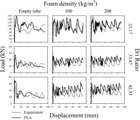
Fig. 5 and 6 show load and displacement curves of aluminum and steel specimens. The results from experiment and FEA simulation are compared in these figures, corresponding to different D/t ratios. In general, the curve is fluctuated up and down in a wavy shape. In the first curve, the load is maximum, so called maximum load. It is observed from those figures that the FEA results are normally laid above the experimental curves. This is because the simulation is perfect and some assumptions are made in the calculation. Taking a rough consideration on influence of density, it is observed that tubes with higher density tend to have higher load curve. This implies that foam filled tubes can absorb more energy than empty tubes, for both aluminum and steel tubes.
[image:3.595.377.488.49.152.2](a) (b) (c)
[image:3.595.102.250.56.159.2]Fig. 4 The typical collapse mode on load displacement curve under quasi-static load: (a) concertina mode, (b)diamond mode, and (c) mix mode. Fig. 3. The universal testing machine with 2,000 kN capacity. Fig. 2. Schematics and boundary condition of model in finite element
[image:3.595.55.282.303.438.2] [image:3.595.319.555.633.697.2]Fig. 5 shows load displacement curves of empty and foam filled aluminum tubes with D/t = 21.17, 33.87 and 42.33. The result from FEA is compared with experimental result and they are in good agreement. It is observed that the load displacement curves of empty tubes fluctuate in a number of wavy shapes but with less number than that of foam filled tubes. It is also observed that as the density of foam is increasing, the value of load is increased. In addition, higher number of peak is obtained at higher foam density.
Fig. 6 illustrates the load displacement curves of empty and foam filled steel tubes. The FEA result agrees well with experimental result. In general, the curves of steels are similar to that of aluminum but with more number of peaks. In addition, the value of load is higher at higher density and higher D/t ratio.
B. Mean crushing load
As the load response of specimen is recorded and plotted as shown in Fig. 5-6, the mean crushing load is calculated as the average value of load from the onset of impact until end. The values of mean crushing loads of steel and aluminum specimens are tabulated in Table III.
TABLEIII
MEAN CRUSHING LOAD OF EMPTY AND FOAM-FILLED TUBE
D/t ρf (kg/m3)
Steel Aluminum
EXP FEA EXP FEA
21.17
0 42.96 51.93 80.32 87.42
100 47.34 53.96 84.27 95.12
200 51.31 56.85 92.34 102.25
33.87
0 37.26 54.75 23.53 26.40
100 48.01 59.25 25.90 30.42
200 62.68 65.16 28.18 35.31
42.33
0 28.84 41.90 25.28 28.45
100 34.71 47.00 26.04 31.47
200 40.64 52.68 31.91 42.13
Considering data from Fig. III, it is observed that the result from FEA is generally higher than that of experiment. The discrepancy may be arisen from the imperfection in experiment. In general, the mean crushing load of foam filled tube is increasing as the density of foam increased. This phenomena is observed for both aluminum and steel tubes.
C. Collapse mode
There are 3 collapse mode achieved in this study. They are concertina mode, diamond mode and mixed mode, as shown in Fig. 7(a) - 7(c), respectively. Fig. 7(d) shows the wall sectioned of collapsed tube, in order to observed the collapse mode more closely. It is observed that mode of collapse achieved from FEA and experiment are quite similar. The collapse modes of all specimens are summarized in Fig. 8.
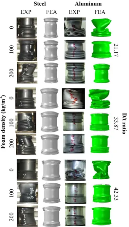
Fig. 8 shows the summary of collapse mode of all specimens corresponding to different D/t ratio and densities. It is observed that the result from FEA is similar to experimental results. All empty steel tubes are failed in concertina mode, while the empty aluminum tubes are failed in diamond mode and changed to mix mode for high D/t ratio. It is also observed that both types of tubes with 100 kg/m3 foam filled are mostly failed in concertina mode, except the steel tubes with D/t=42.33 which failed in mix mode. Number of fold in steel tubes is more than that of aluminum tubes and tends to increase for higher D/t ratio. Considering the 200 kg/m3 density foam filled tube, all specimens are failed in concertina mode. Number of folds is increasing as the value of D/t is increased. It should be noted that steel tubes is tending to buckling in foam filled cases. The buckling mode is normally not desirable since it reduces the crashworthiness capacity of structures.
[image:4.595.52.292.62.268.2]From the result, it is generally saying that empty aluminum tube is failed in diamond mode or mix mode. Its
Fig. 7 Typical collapse mode under axial load: (a) concertina mode, (b) diamond mode, (c) mixed mode. (d) half view with foam-filled tube.
[image:4.595.326.544.407.522.2] [image:4.595.50.291.573.757.2]collapse mode is changing to be concertina mode when tube is filled with PU foam as well as the number of fold is also increasing. In case of steel, the empty tube is failed in concertina mode and changed to be diamond mode and mix mode when it is filled with foam. In addition, steel tube can be failed in buckling mode for high density foam filled. This implies that filling foam in steel tube may be not suggestive because it may cause low efficiency collapse mode. In contrast, aluminum tube filled with PU foam tends to be more efficient in terms of crashworthiness since it failed in concertina mode which good in energy absorption [19, 20].
D. Response of energy absorption
Fig. 9 shows the energy absorption (Ea) of specimens, both from FEA and experiment. In general, it is observed that the value from FEA is going well with experiment.
From Fig. 9, tubes with every D/t can absorb higher energy as the foam density is increasing. Considering the influence of D/t, steel and aluminum tubes with D/t =21.17 can absorb higher energy than D/t= 33.87 and 42.33 tubes, respectively. This is due to the influence of wall thickness.
In case of tubes with D/t=21.17, aluminum and steel tubes filled with foam are able to absorb more energy as the foam density increases. At this D/t, aluminum tube is more energy efficient than steel. However, in cases of D/t=33.87 and D/t=42.33, steel tube seems to have slightly higher energy absorption capacity. In addition, as the value of D/t increases, the energy absorption capacity is tending to decrease.
E. Response of specific energy absorption
Fig. 10 illustrates the specific energy absorption (Es) of specimens. For tube with D/t=21.17, the value of Es is higher than that of D/t=33.87 and D/t=42.33, respectively. In addition, Es of tubes with foam filled is decreased, compared to empty tube. Comparing aluminum and steel tube, it is found that aluminum tube has higher Es value than steel tube at D/t = 21.17 and for every foam densities. For D/t=33.8 and 42.33, empty aluminum tube has higher Es value than steel tubes. In case of foam filled D/t=33.8 and 42.33, steel and aluminum tubes have similar value of Es, and tend to decrease as the density of foam is increasing.
IV. CONCLUSION
[image:5.595.310.547.106.214.2] [image:5.595.66.276.204.573.2]This study reveals that filling foam in tube can change mode of collapse of specimens. In case of aluminum tube, its mode of collapse changes from diamond or mix modes to be concertina mode. While the steel tube is changing from concertina mode to mix mode and tend to buckling for higher foam density. The energy absorption capacity of aluminum and steel tubes can be enhanced by filling foam Fig. 10 The specific energy absorption of empty and foam-filled tube. Fig. 9 The energy absorption of empty and foam-filled tube.
[image:5.595.307.546.421.520.2]as the value of Ea is increasing for higher foam density. However, this effect is decreasing for higher D/t tube. Considering the specific energy absorption, the value of Es seems to decrease as the value of foam density is increasing. This implies that, although filling foam technique can improve the energy absorption but also increase net weight of structure.
ACKNOWLEDGMENT
Authors wish to thank Department of Mechanical Engineering, Faculty of Engineering, Ubon Ratchathani University, for supporting all test rigs.
REFERENCES
[1] D.-K. Kim, S. Lee, and M. Rhee, “Dynamic crashing and impact energy absorption of extruded aluminum square tubes”, Materials & Design. vol. 19: pp.179-185, 1998.
[2] M. Langseth, O.S. Hopperstad, and A.G. Hanssen., “Crash behaviour of thin-walled aluminium members”, Thin. Wall. Struct. vol. 32, pp. 127-150, 1998.
[3] M. Langseth, O.S. Hopperstad, and T. Berstad., “Crashworthiness of aluminium extrusions: validation of numerical simulation, effect of mass ratio and impact velocity”, Int. J. Impact. Eng., vol. 22, pp 829-854, 1999.
[4] A.A. Nia and J.H. Hamedani., “Comparative analysis of energy absorption and deformations of thin walled tubes with various section geometries”, Thin. Wall. Struct. 48: 946-954, 2010.
[5] M. Yamashita, M. Gotoh, and Y. Sawairi., “Axial crush of hollow cylindrical structures with various polygonal cross-sections - Numerical simulation and experiment”, J. Mater. Process. Tech., vol. 140, pp 59-64, 2003. [6] N.K. Gupta and Venkatesh., “A study of the influence
of diameter and wall thickness of cylindrical tubes on their axial collapse”, Thin. Wall. Struc., vol. 44, pp. 290-300, 2006.
[7] P.R. Mantena and R. Mann., “Impact and dynamic response of high-density structural foams used as filler inside circular steel tube”, Composite Structures. vol. 61, pp. 291-302, 2003.
[8] I.W. Hall, M. Guden, and T.D. Claar., “Transverse and longitudinal crushing of aluminum-foam filled tubes”, Scripta Materialia. vol. 46, pp 513-518, 2002.
[9] Q.C. Wang, Z.J. Fan, L.J. Gui, Z.H. Wang, and Z.L. Fu., “Experimental studies on the axial crash behavior of aluminum foam-filled hat sections”, Frontiers of Mechanical Engineering in China., vol. 4, pp. 381-387, 2006.
[10]L. Mirfendereski, M. Salimi, and S. Ziaei-Rad., “Parametric study and numerical analysis of empty and foam-filled thin-walled tubes under static and dynamic loadings”, International Journal of Mechanical Sciences., vol. 50, pp. 1042-1057, 2008.
[11]A.A. Singace and H. Elsobky., “Further experimental investigation on the eccentricity factor in the progressive crushing of tubes”, International Journal of Solids and Structures., vol. 33, pp. 3517-3538, 1996. [12]U.E. Ozturk and G. Anlas., “Finite element analysis of
expanded polystyrene foam under multiple compressive loading and unloading”, Materials and Design, vol. 32, pp 773-780, 2011.
[13]N.K. Gupta and R. Velmurugan., “Consideration of internal folding and non-symmetric fold formation in axisymmetric axial collapse of round tubes”, International Journal of Solids and Structures., vol. 34, vol. 2611-2630, 1997.
[14]A.G. Hanssen, M. Langseth, and O.S. Hopperstad. “Static and dynamic crushing of circular aluminium extrusions with aluminium foam filler”, International Journal of Impact Engineering., vol. 24, pp. 475-507, 2000.
[15]H. Jin, W.Y. Lu, S. Scheffel, T.D. Hinnerichs, and M.K. Neilsen. “Full-field characterization of mechanical behavior of polyurethane foams”, International Journal of Solids and Structures., vol. 44, pp. 6930-6944, 2007.
[16]A.G. Hanssen, M. Langseth, and O.S. Hopperstad., “Static and dynamic crushing of square aluminium extrusions with aluminium foam filler”, International Journal of Impact Engineering., vol. 24, pp. 347-383, 2000.
[17]Q. Wang, Z. Fan, and L. Gui. “Theoretical analysis for axial crushing behaviour of aluminium foam-filled hat sections”, International Journal of Mechanical Sciences., vol. 49, pp. 515-521, 2007.
[18]C.J. Zhang, Y. Feng, and X.B. Zhang., “Mechanical properties and energy absorption properties of aluminum foam-filled square tubes”, Transactions of Nonferrous Metals Society of China., vol. 20, pp. 1380-1386, 2010.
[19]K.R.F. Andrews, G.L. England, and E. Ghani., “Classification of the axial collapse of cylindrical tubes under quasi-static loading”, Int. J. Mech. Sci., vol. 25, pp. 687-696, 1983.