Abstract— Scientists all over the world are making predictions about the ill effects of Global warming and its consequences on the mankind. Conventional Fuel Fired Electric Power Stations contribute nearly 21.3% of the Global Green House Gas emission annually. Hence, an alternative for such Power Stations is a must to prevent global warming. One fine alternative that comes to the rescue is theOcean thermal energy conversion (OTEC) Power Plant, the complete Renewable Energy Power Station for obtaining Cleaner and Greener Power. Even though the concept is simple and old, recently it has gained momentum due to worldwide search for clean continuous energy sources to replace the fossil fuels. The design of a 5 Megawatt OTEC Pre-commercial plant is clearly portrayed to brief the OTEC technical feasibility along with economic consideration studies for installing OTEC across the world. OTEC plant can be seen as a combined Power Plant and Desalination plant. Practically, for every Megawatt of power generated by hybrid OTEC plant, nearly 2.28 million litres of desalinated water is obtained every day. Its value is thus increased because many parts of the globe are facing absolute water scarcity. OTEC could produce enough drinking water to ease the crisis drought-stricken areas. The water can be used for local agriculture and industry, any excess water being given or sold to neighboring communities.
Index Terms—Desalinated water, Ocean Temperature Differences, Rankine Cycle, Renewable Energy.
I. INTRODUCTION
CEAN thermal energy conversion is a hydro energy conversion system, which uses the temperature difference that exists between deep and shallow waters in tropical seas to run a heat engine. The economic evaluation of OTEC plants indicates that their commercial future lies in floating plants of approximately 100 MW capacity for industrialized nations and smaller plants for small-island-developing-states (SIDS). The operational data is needed to earn the support required from the financial community and developers. Considering a 100 MW (4-module) system, a 1/5-scaled version of a 25 MW module is proposed as an appropriate size. A 5 MW pre-commercial plant is directly applicable in some SIDS. OTEC works on Rankine cycle, using a low-pressure turbine to generate electric power. There are two general types of OTEC design: closed-cycle plants utilize the evaporation of a working fluid, such as ammonia or propylene, to drive the turbine-generator, and open-cycle plants use steam from evaporated
R. Magesh is with Coastal Energen Pvt. Ltd., Chennai 600 006, Tamilnadu, India (e-mail: wellingtonmagesh@ gmail.com).
sea water to run the turbine. Another commonly known design, hybrid plants, is a combination of the two. In fact, the plants would cool the ocean by the same amount as the energy extracted from them. Apart from power generation, an OTEC plant can also be used to pump up the cold deep sea water for air conditioning and refrigeration, if it is brought back to shore. In addition, the enclosed sea water surrounding the plant can be used for aquaculture. Hydrogen produced by subjecting the steam to electrolysis during the OTEC process can fuel hybrid automobiles, provided hydrogen can be transported economically to sea shore. Another undeveloped opportunity is the potential to mine ocean water for its 57 elements contained in salts and other forms and dissolved in solution. The initial capital cost of OTEC power station would look high, but an OTEC plant would not involve the waste-treatment or astronomical decommissioning costs of a nuclear facility. Also, it would offset its expense through the sale of the desalinated water.
II. LITERATUREREVIEW
Jacques Arsene d’Arsonval (1881) was the first to coin the term OTEC in France. Georges Claude (1930) built an experimental 22-Kilowatt (gross) open-cycle shore based OTEC system at Matanzas Bay, Cuba. French researchers (1956) designed a 3-Megawatt (gross) open-cycle OTEC plant for Abidjan on Africa’s west coast. But the plant never completed because of competition with inexpensive hydroelectric power. The Natural Energy Laboratory of Hawaii Authority (NELHA), established closed-cycle floating OTEC demonstration plant named “Mini-OTEC” (1979) producing 53 kW of gross power and 18 kW of net power. Toshiba & TEPC (Japan) demonstrated a shore-based, 120 kW (gross) closed-cycle OTEC plant (1982) in the Republic of Naura in the Pacific Ocean, producing 31.5 kW of net power during continuous operating tests. NELHA (1993) installed an open-cycle OTEC plant at Keahole Point, Hawaii, producing 50 kW of net power, surpassing the record set by the Japanese system (1982). A 210 kW (gross) open cycle shore based OTEC plant facility off the island of Hawaii was designed built and run successfully by NELHA (US) for a period of 6 years (1993-1998) by the US Government with a net power production of 100 kW.
Saga University (Japan) built 75 kW (1984) and 9 kW (1995) gross power closed-cycle Lab Models at Saga in Japan. Since 1998, National Institute of Ocean Technology (NIOT),
OTEC Technology- A World of Clean Energy
and Water
R. Magesh
Government of India and Saga University in Japan were involved in the design, development and demonstration of a 1 MW (gross) OTEC floating plant demonstration project off the Tuticorin coast in Tamil Nadu, which will be the first ever MW range plant established anywhere in the world. The unit situated 60 km from Tuticorin, is installed on a 68.5 m barge, the Sagar Shakthi, which houses a Rankine Cycle based power plant. OTEC projects on the drawing board include a small plant for the U.S. Navy base on the British-occupied island of Diego Garcia in the Indian Ocean. OCEES International, Inc. is working with the U.S. Navy on a design for a proposed 13 MW OTEC plant, which would replace the current power plant running diesel generators. This OTEC plant would also provide 1.25 Millions of Gallons per Day of potable water to the base. A private U.S. company has proposed to build a 10 MW OTEC plant at Guam. Lockheed Martin's Alternative Energy Development team is currently in the final design phase of a 10 MW closed cycle OTEC pilot system which will become operational in Hawaii by 2012-2013. This system is being designed to expand to 100 MW commercial systems in the near future. Near Hawaii Island, Architect and Engineer Dominic Michaelis, Alex Michaelis along with Trevor Cooper-Chadwick of Southampton University are currently
developing the floating Hexagonal Energy Island that will harness energy from OTEC, as well as from winds, sea currents, waves, and the sun. Energy Island Project carried out in Hawaii is being funded and led by the US Government. To shoulder the entire global energy consumption, based on 2000 figures, 52971 Energy Islands would be needed, occupying a total area of 111 x 111 kilometers.
III. OTEC TECHNICAL FEASIBILITY
A. Design of a Pre- Commercial 5 MW Floating Plant The design of a 5 MW hybrid OTEC power module is based on a Closed-Rankine cycle for electricity production and on a second stage, using the effluent water streams from the power cycle, for desalinated water production. The entire setup of power and water cycles of OTEC module is housed in a barge or ship. The major components in the system include Flash Evaporator, Turbo-generator, Condenser, Warm water supply pumps and Cold water supply pumps. Anhydrous Ammonia having a low boiling point of −33.34 °C (239.81 K) is used as
the working fluid in closed Rankine cycle.
20
60
O
c
e
a
n
D
e
p
th
(
M
e
te
rs
)
5 MW OTEC Vessel
1000
Warm
Water Pipe
Mixed Water
Pipe
Ocean Surface
Cold Water Pipe
Bottom Mooring Line
1100
Anchor Weight Bottom Weight
Sea Floor
Anchor Top Fitting
Pipe Pendant 0
Transfer Hose
[image:2.612.82.521.365.674.2]Vessel Bow
Fig. 1 Mooring arrangement for 5 MW OTEC plant Warm water pump is used to pump warm sea water to the
Evaporator for heating the working fluid namely Ammonia.
Ammonia is heated to its boiling point and phase transformation takes places liberating ammonia vapour, which drives the 4-stage axial turbine to generate electric power.
Fig. 2 Large Offshore OTEC Plant
Ammonia expanded in the turbine is condensed back to liquid state in condenser using the cold water supplied by cold water supply pumps. This condensed ammonia is pumped back to the evaporator with the help of Ammonia feed pumps. Thus the cyclic process of Ammonia circulation is repeated continuously to generate electric power.
The seawater effluents from the power cycle exhibit a
temperature difference of 12 °C. This residual thermal gradient could not be used in an additional power stage, but it allows the production of significant amounts of desalinated water through a Desalinated Water Cycle (DWC) or second stage water production. The seawater pumps used for pumping both warm and cold waters are of vertical, mixed flow type due to the low head and high discharge combination. Two identical pumps are to be connected in parallel on both warm water and cold water side and are driven by a variable speed drive to adjust the flow rates. As the system is highly sensitive to the flow variables, a variable speed drive is an essential component in an OTEC system.
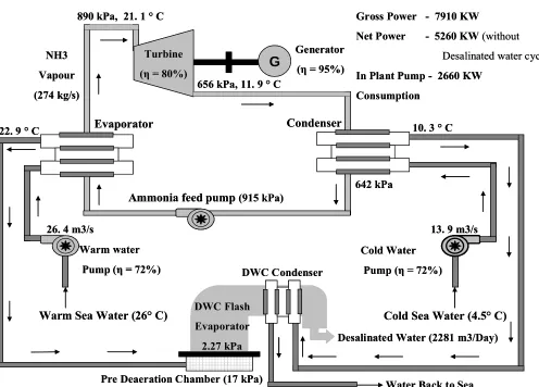
B. Electric Power Cycle
The power output for this cycle varies as a function of surface water temperature (the cold water temperature is essentially constant) by 860 kW per °C.
Condenser
Cold Sea Water (4.5° C)
Turbine
(η= 80%)
G
Evaporator
Ammonia feed pump
(915 kPa)Warm water Pump (η= 72%)
Cold Water Pump (η= 72%)
Warm Sea Water (26° C)
Generator (η= 95%) NH3
Vapour (274 kg/s)
22. 9 ° C 10. 3 ° C
890 kPa, 21. 1 ° C
656 kPa, 11. 9 ° C
DWC Condenser
26. 4 m3/s 13. 9 m3/s
642 kPa
Pre Deaeration Chamber (17 kPa) DWC Flash Evaporator
2.27 kPa Desalinated Water (2281 m3/Day)
Water Back to Sea Gross Power - 7910 KW
Net Power - 5260 KW(without Desalinated water cycle)
In Plant Pump - 2660 KW Consumption
[image:3.612.53.549.292.648.2]Assuming temperatures of 26 °C and 4.5 °C for the surface and deep ocean waters, in the electricity production mode, a gross power output of 7920 kW, using off-the-shelf technology, is sufficient to produce 5260 kW-net with an in-plant consumption of 2660 kW. The power and water cycles are housed in a barge or ship with the electricity transmitted to shore via a 15 cm submarine power cable and the desalinated water via a small, 15 to 16 cm diameter hose pipe. The baseline seawater flow rates are 26.4 m3/s of warm water and 13.9 m3/s of cold water. A 2.74 m (inside diameter) glass fiber reinforced plastic (FRP) cold water pipe will be suspended from the barge to a depth of 1000 m. Warm seawater will be drawn in through a 4.6 m (inside diameter) FRP pipe from a depth of 20 m. The mixed effluent will be discharged through a 5.5 m (inside diameter) FRP pipe at a depth of 60 m. This discharge depth has been selected to minimize the environmental impact.
C. Desalinated Water Cycle
The Desalination Water Cycle is an Open Cycle-OTEC system without the turbine. In a low-pressure vessel, or evaporator, the warm seawater is partially flashed into steam. The evaporator is connected to two surface condensers, where the steam is converted into desalinated (fresh) water by exchanging heat with the cold seawater. During this process, dissolved gases, mainly nitrogen and oxygen, are released from the warm seawater when pressures as low as 2 percent of an atmosphere are reached. These non-condensable gases must be evacuated continuously from the second condenser, or vent condenser, by a vacuum compressor to prevent accumulation and sustain the required low operating pressures. Non-condensable gases also adversely affect condensation performance through a blanketing effect at the heat exchanger walls. To reduce the impact of released non-condensable gases, a pre-deaeration chamber at about 17 kPa is installed below the flashing chamber, so that much outgassing occurs before steam generation, and at a higher pressure more suitable for compression. Moreover, gases are discharged into the warm seawater effluent at sub atmospheric pressures of about 30 kPa, a procedure that not only saves power, but also restores the gas content of the warm seawater before it returns to the ocean.
IV. SCOPE FOR OTEC DEVELOPMENTACROSS THE WORLD The economies and social structure of the vast majority of what is now considered Small Island Developing States (SIDS) were developed under colonial rule. When the majority of these countries became independent nations in the later half of the twentieth century, they inherited economies that were based principally on providing commodities to the former ruling nations. This relationship remained in place until the advent of the World Trading Organization (WTO) in 1994. Under the WTO global rules for “fair” trade, there would no longer be continuation of preferential markets for the commodities from these former colonies beyond an agreed period of time. After that period, between 5 to 10 years in most
cases, these former small colonies had to compete with other international producers. As a result of the coming into force of WTO rules, Less Developed Countries and SIDS have experienced loss of preferential access for their exports to developed country’s markets. The increase in the cost of conventional fuel makes it difficult to run their power plants thereby leading to heavy power deficit. Ever increasing Power deficit severely affects the growth of the Industrial and Agriculture sectors in these nations resulting in the Decline of
TABLE I
CHARACTERISTICS OFPRE-COMMERCIAL 5 MW OTEC HYBRID PLANT
Ship Platform - General Details
Length 122 m
Breadth 30 m
Operating Draft 9 m
Depth 16 m
Weight 32000 Metric tons
Wave Height 3.65 m
Surface Currents 3 Knots (1.5 m/s) Warm Surface Water Temperature 24° C - 28° C Cold Water Temperature 4° C - 5° C CWP Connection Type Double Gimbal Joint
Mooring System CAM System
Capital Cost Estimate 13000 US $/ kW (Min.) Estimated Operational Life 30 years
Electric Power Cycle
Power Output per °C 860 kW/ °C Mass Flow of Ammonia 274 kg/s Ammonia Pump Consumption 160 kW Gross Power Output 7920 kW Net Power Output (Before Desalination) 5260 kW In Plant Consumption 2660 kW Submarine Power Cable Diameter 0.15 m Submarine Power Cable Length Up to 150 miles Desalinated Water Cycle (DWC)
Desalinated Water Discharge Nearly 2281 m3/ Day Net Power Output (After Desalination) 5100 kW
Power Consumed for Desalination (II
Stage) 160 kW
Desalinated Water Pipe Diameter 0.16 m Cold water pipe
Cold Water Pipe Inner Diameter 2.74 m Cold Water Pipe Depth 1000 m Cold Water Temperature 4.5° C Cold Water Discharge 13.9 m3/s Cold Water Pump Consumption 1280 kW Warm Water Pipe
Warm Water Pipe Inner Diameter 4.6 m Warm Water Pipe Depth 20 m Warm Surface Water Temperature 26° C Warm Water Discharge 26.4 m3/s Warm Water Pump Consumption 1190 kW Mixed Effluent Pipe
Mixed Effluent Pipe Inner Diameter 5.5 m Mixed Effluent Pipe Depth 60 m
Domestic Food production and Increasing Imports. Inability to compete with the international challenge leads to Loss of Market and Declining Value of Traditional Exports in SIDS. Geographical isolation and lack of basic facilities in SIDS has
made it Difficult for them to attract Foreign Direct Investment (FDI).
The GDP Real Growth rate (%) in vast majority of these countries has seen a decline in the past three years (2007-2009), due to lack of electric power and fresh water for industrial and irrigation purpose. OTEC of 5 MW capacity would be a better option to be installed in the SIDS and other less developed countries having Ocean thermal resources in their Exclusive Economic Zone (EEZ) for fulfilling the power and fresh water demands. Table II shows the less developed Countries with adequate Ocean Thermal Resources 25 Kilometers or less from the shore.
V. COST OF ELECTRICITY PRODUCTION
OTEC is capital-intensive, and the very first commercial plants will require a substantial capital investment. Economic evaluation of OTEC plants are based on their commercial future i.e. 100 MW floating plants. The following formula is used to calculate the production cost of electricity P, over the assumed life for the OTEC plant (nominal value: 30 years):
P ($/kWh)=[(FC x CC) + (OM x G x CR)/ (NP x CF x 8760)] Where,
P - Cost of electricity production ($/kWh) FC - Annual fixed charge (e.g.: government loan) CC - Plant overall investment capital cost, in $
OM - Operation and maintenance yearly $ expenditures G - Present worth factor, in years
CR - Capital recovery factor NP - Net power production, in kW CF - Production capacity factor 8760 - Number of hours in one year
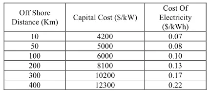
Table III shows the results of economic evaluation of 100 MW OTEC plant, indicating that the capital cost and cost of electricity production decreases with the decrease in off shore distance of the plant.
[image:5.612.336.551.520.613.2]Reduction in Cost of Electricity production can be expected for OTEC in future with increase in experience and development of technology. Desalination process for the production of fresh water will yield ample profits, as millions of liters of fresh water requirements in SIDS were satisfied by operating separate Desalination plants across the country.
TABLE III
COST ESTIMATES FORFUTURE 100 MWOTEC HYBRID PLANT
Off Shore
Distance (Km) Capital Cost ($/kW)
Cost Of Electricity
($/kWh)
10 4200 0.07
50 5000 0.08
100 6000 0.10
200 8100 0.13
300 10200 0.17
400 12300 0.22
COE for 10 % Fixed Rate, 20 years, Annual O&M 1% of Capital Cost. TABLE II
POTENTIAL SITESWITH OCEAN THERMAL RESOURCES
Country/ Area ΔT (°C) D (Km) GDP Real Growth Rate (%) 2007 est. 2008 est. 2009 est. Africa
Benin 22-24 25 4.5 4.8 3.2
Gabon 20-22 15 5.6 2 -2.8
Ghana 22-24 25 6.3 7.3 4.7
Kenya 20-21 25 7 1.7 1.8
Mozambique 18-21 25 7.4 6.8 4.3 Sao Tome and
Principe 22 1 ~10 6 5.5 4.3
Somalia 18-20 25 2.6 2.6 2.6
Tanzania 20-22 25 7.1 7.1 4.5 Latin America and Caribbean
Bahamas 20-22 15 2.8 -1.5 -4 Barbados 22 1 ~10 3.3 0.7 -2.8
Cuba 22-24 1 7.3 4.3 1
Dominica 22 1 ~10 1.8 3.2 1.1 Dominican
Republic 21-24 1 8.5 5.3 -0.3
Grenada 27 1 ~10 4.9 2.2 -4
Haiti 21-24 1 3.4 1.3 -0.5
Jamaica 22 1 ~10 1.4 -0.6 -4 Saint Lusia 22 1 ~10 1.7 0.7 1.7 Saint Vincent
&
Grenadines 22 1 ~10 6.9 2.8 -6.5 Trinidad and
Tobago 22-24 10 5.5 3.5 -2.7
US Virgin
Islands 21-24 1 NA 2
Indian and Pacific Oceans
Comoros 20-25 1 ~10 -1 0.5 1 Cook Islands 21-22 1 ~10 0.1 NA Fiji 22-23 1 ~10 -6.6 0.2 -1
Guam 24 1 NA
Kiribati 23-24 1 ~10 -0.5 3.4 1.5 Maldives 22 1 ~10 7.2 5.8 -4 Mauritius 20-21 1 ~10 5.5 5.3 2.1 Philippines 22-24 1 7.1 3.8 0.9 Samoa 22-23 1 ~10 6.1 -3.4 -0.8 Seychelles 21-22 1 9.7 -0.9 -8.7 Solomon
Islands 23-24 1 ~10 10.3 7.3 0 Vanuatu 22-23 1 ~10 6.8 6.6 3.8
ΔT (°C) =Temperature difference of water between 0 m and 1000 m,
VI. CONCLUSION
Conventional power plants pollute the environment more than an OTEC plant would and, as long as the sun heats the oceans, the fuel for OTEC is unlimited and free. The unit cost of electricity will become competitive with that of the conventional fossil fuel burning power plant as well as nuclear in the near future. The desalination technology as by-product of the OTEC can produce a large amount of fresh water from seawater for which the island nations and the other desert countries longing eagerly. It is the OTEC, which has a potential to become powerful solution to three greatest global issues of Clean Energy, Fresh Water and Food without vital harmful influence on irreplaceable earth environment.
REFERENCES
[1] Claude G. (1930), "Power from the Tropical Seas" in Mechanical Engineering, Vol. 52, No.12, 19, pp.1039-1044.
[2] Hubbard H.M (1991), “The Real Cost of Energy”, Scientific American, April 1991, Vol. 264, No. 4, pp. 18-23.
[3] Nihous G.C. and Vega L.A. (1991), “A Review of Some Semi-empirical OTEC Effluent Discharge Models”, in Oceans ‘91, Honolulu, Hawaii. [4] Quinby-Hunt M.S., Sloan D., and Wilde P. (1987), “Potential
Environmental Impacts of Closed-cycle Ocean Thermal Energy Conversion”, in Environ Impact Assess Rev, Elsevier Science Pub. Co., Inc., New York, NY, pp. 169-198.
[5] Quinby-Hunt M.S., Wilde P., and Dengler A.T (1986), “Potential Environmental Impacts of Open-cycle Ocean Thermal Energy Conversion”, in Environ Impact Assess Rev, Elsevier Science Pub. Co., Inc., New York, NY, pp. 77-93.
[6] Syed M.A., Nihous G.C., and Vega L.A. (1991), “Use of Cold Seawater for Air Conditioning”, OCEANS ‘91, Honolulu, Hawaii.
[7] Sverdrup H.V., Johnson M.W., and Fleming P.H. (1942), “The Oceans: Their Physics, Chemistry, and General Biology”, Prentice-Hall, New York.
[8] Vega L.A., and Nihous G.C. (1988), “At-Sea Test of the Structural Response of a Large Diameter Pipe Attached to a Surface Vessel”, Paper #5798, Offshore Technology Conference, Houston, May 1988. [9] Vega L.A. (1992), “Economics of Ocean Thermal Energy Conversion
(OTEC)” in R.J. Seymour, ed. Ocean Energy Recovery: The State of the Art, American Society of Civil Engineers, New York.