Abstract— Fuzzy logic or Fuzzy set theory is given much emphasis in recent years especially in power electronics based control applications. Fuzzy logic has met with growing interest in many motor control applications due to its non-linearity, handling features and independence of plant modeling. This paper describes application of fuzzy logic in speed control system for Electrical Machines: DC motors and AC Induction motors. The design of fuzzy logic controlled for Electrical Machines are very similar. The controller designed is based on proportional, Integral and derivative fuzzy reasoning. It directly transforms the inputs: speed error and its rate of change to the output quantity and fuzzy logic speed controller is employed in the outer loop. The complete scheme of the Electrical machine incorporating the FLC is implemented using MATLAB (Math works). The performances of the electrical machines are investigated with (PID) controller for different operating conditions. The response including a fuzzy logic controller is also obtained. The comparison of results shows that the controller with FLC is more robust and hence found to be a suitable addition to the conventional PID controller for high performance industrial drive applications.
Index Terms—Electrical Machines, Fuzzy Logic Controller (FLC), Integral Absolute Error (IAE), Non linear systems, PID controllers, Simulation Analysis.
I. INTRODUCTION
Classic Control has proven for a long time to be good enough to handle control tasks on Electrical Machines, however this implementation relies on an exact mathematical model of the plant to be controlled and not simple mathematical operations. In the last decades, many control techniques have been developed providing good performance. However, the desired drive specifications are still not satisfied perfectly and their algorithms are too complex. On the other hand, Fuzzy Logic Controller (FLC) [1] is based on single human reasoning models, therefore their design are
This work was supported in part by the Department of Electrical Engineering, University College of Engineering (A), Osmania University.
Gaddam Mallesham is with the Department of Electrical Engineering, University College of Engineering (A), Osmania University, Hyderabad, A.P., INDIA,500 007 (e-mail: [email protected]).
K. B. Venakta Ramana with the University Building Division, Osmania University, Hyderabad, and A.P., INDIA,500 007 (e-mail: [email protected]).
guided by intuition, expert knowledge and engineering. Fuzzy Logic Controllers can be classified according to their input and output variables, when typical variables such as "error", "change in error" and "error sum" are used alone or combined, FLC's become "Fuzzy Proportional", "Fuzzy Integral", and so on[2]. This paper presents the experimental results of the basic ideas of the Fuzzy Logic Controllers applied to Electrical Machines, showing the high level of suitableness of Fuzzy Logic on speed control of DC motors and AC motors.
The fuzzy logic approach has been the object of an increasing interest and has found applications in many domains. The main advantage of fuzzy logic control when compared to conventional control is the fact that no mathematical modeling is required for the controller design. Fuzzy logic has been successfully used to control ill-known or complex systems where precise modeling is difficult or impossible. In motion control systems, fuzzy logic can be considered as an alternative approach to conventional feedback control. It has been demonstrated that dynamic performance of electric drives as well as robustness with regard to parameter variations can be improved by adopting the non-linear speed control techniques. Fuzzy control is a linear control and it allows the design of optimized non-linear controllers to improve the dynamic performance of conventional regulators. In the literature, one can find the application of fuzzy logic in the control of various systems: DC motor and Induction motors, AC Servo, etc.
The motor control issues are traditionally handled by fixed gain proportional, integral and derivative (PID) controller. However, the fixed gain controllers are very sensitive to parameter variations, load disturbances, etc. so, the controller parameters have to be adapted. The problem can be solved by several control techniques and design of all of the above controllers depends on the exact system mathematical model. However, it is often difficult to develop an accurate system mathematical model due to unknown load variation, unknown and unavoidable parameter variations due to saturation, temperature variations and system disturbances. In order to overcome the above problems, recently the fuzzy logic controller (FLC) is being used for motor control purpose, the mathematical tool for this is the fuzzy set theory introduced by Prof. Zadeh [3]. As compared to the conventional controllers
Improvement in Dynamic Response of
Electrical Machines with PID and Fuzzy Logic
Based Controllers
and their adaptive versions the FLC has some advantages such as: (1) it does not need any exact system mathematical model; (2) it can handle non-linearity of arbitrary complexity and (3) it is based on the linguistic rules with IF-THEN general structure which is the basis of human logic.
In this paper, the application of fuzzy logic to control electrical machines is investigated. Fuzzy logic control principle is considered for the design of the speed controller. The control performance of this fuzzy logic controller is evaluated by simulation for different operating conditions and by comparing with the results of the conventional controller using the Integral of Time by Absolute Error criterion.
II. PRINCIPLE AND CONTROL OF PROPOSED DC MOTOR
A. Introduction
The speed of DC motors can be adjusted within wide boundaries so that this provides easy controllability and high performance[4]. DC motors used in many applications such as still rolling mills, electric trains, electric vehicles, electric cranes and robotic manipulators require speed controllers to perform their tasks. Speed controller of DC motors is carried out by 'means of voltage control, in 1981 fustly by Ward Leonard [5]. The regulated voltage sources used for DC motor speed control have gained more importance after the introduction of thyristor as switching devices in power electronics. Then semiconductor components such as MOSFET, IGBT and GTO have been used as electric switching devices [6, 7].
In this study, the speed response of a DC motor exposed to fixed armature voltage was investigated for both under loaded and unloaded operating conditions. The DC motor was operated for a required reference speed under loaded and unloaded operating conditions using PID and Fuzzy logic control methods.
B. Motor Model
The resistance of the field winding and its inductance of the motor used in this study are represented by Rf and Lf,
respectively. The resistance of the armature and its inductance are shown by Ra and La respectively in dynamic model.
Armature reaction effects are ignored in the description of the motor. This negligence is justifiable to minimize the effects of armature reaction since the motor used has either interpoles or compensating winding. The fixed voltage V, is applied to the field and the field current settles down to a constant value. A linear model of a simple DC motor consists of a mechanical equation and electrical equation as determined in the following equations:
load m
a m m
m
K
I
b
M
dt
dw
J
.
.
.
(1)
m b a a a a
a
V
I
R
K
dt
dI
L
.
.
.
(2) [image:2.612.317.560.153.315.2]
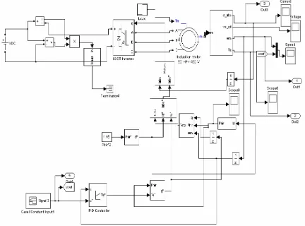
The dynamic model of the system is formed using these differential equations and the Matlab Simulink block with PID controller as shown in figure (1).
Fig. 1 MATLAB/Simulink model of DC motor with PID controller
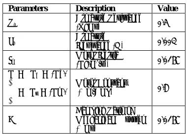
[image:2.612.341.531.411.547.2]The parameters of DC motor used in this study are shown in Table 1.
TABLE IParameters of the DC Motor model used
Parameters Description Value
Ra Armature Resistance (Ohms) 0.5
La Armature Inductance (H) 0.003
Jm Motor Inertia (Kg.m2/s2) 0.0167
K = Ke = (Kb.
Φ)
= Kt = (Km.
Φ)
Motor Constant
(Nm/Amp) 0.8
B
Damping Ratio of Mechanical system (Nms)
0.0167
The speed control of the DC motor using conventional PID controller and Fuzzy logic Controller is implemented and the simulation results discussed in the next sections.
III. PRINCIPLE AND CONTROL OF PROPOSED INDUCTION
MOTOR
machine. Because there is no loss in brush contacts or mechanical friction, it is of a high efficiency
A. Principle of Operation
The stator is similar to the stator of a synchronous machine. It is fed with a 3-phase alternating current and provides a rotating flux. This flux rotates at “synchronous speed”
p
f
N
s120
(in rpm) where (f) if the source frequency and(p) the number of poles on the machine. Or:
s
rad
p
f
s
/
4
(3)The rotor has either a 3 phase short-circuited winding, or any conducting elements. In a study we will consider a 3-phase winding on the rotor (wound rotor machine). The revolving field induces a flux in the rotor windings. Since the windings are short circuited, a current is flowing and that current produces a flux of its own. According to Lenz’s law, this flux will oppose the flux which created it, and hence a torque is developed on the shaft. If this torque is higher than the load torque, the rotor will start to rotate. Under no load, the rotor current will have a very low frequency [8]. This also called an “Asynchronous Machine”. At operating speed, the rotor currents will have the frequency of the relative motion between rotor and stator rotating speed.
Hence the rotor frequency is
shaft S
r
N
N
N
(4)The relative speed is called the slip
S shaft S
shaft S
S r
N
N
N
N
s
(5) [image:3.612.47.299.399.474.2]When the rotor is stationary (start), the slip is 1 and we have the equivalent of a short-circuited transformer (Primary is the stator, secondary is the rotor). The dyanamic model of the Induction motor using PID controller is developed and is shown in figure (2).
Fig.2 MATLAB/Simulink model of Induction motor
The parameters of the Induction motor used in this study are shown in Table II
TABLE II Parameters of the Induction motor used in this study
The simulation results of Induction motor using PID controller is discussed in the next sections
IV. FUZZY LOGIC CONTROLLER (FLC) DESCRIPTION AND
DESIGN
The concept of fuzzy logic (FL) was conceived by Prof. Lofti Zadeh, a professor at the University of California at Berkley [9] and presented not as a control methodology, but as a way of processing data by allowing partial set membership rather than crisp set membership or non-membership. This approach to set theory was not applied to control systems until the late 70’s due to insufficient small-computer capability prior to that time. Professor Zadeh reasoned that people do not require precise, numerical information input, and yet they are capable of highly adaptive control. If feedback controllers could be programmed to accept noisy, imprecise input, they would be much more effective and perhaps easier to implement.
FL is a problem-solving control system methodology that lends itself to implementation in the system ranging from simple, small, embedded micro-controllers to large, networked, multi-channel PC or workstation-based data acquisition and control systems. It can be implemented in hardware, software, or a combination of both. FL provides a simple way to arrive at a definite conclusion based upon vague, ambiguous, imprecise, noisy, or missing input information. FL’s approach to control problems mimics how a person would make decisions, only much faster. [10, 11]
A. FLC Designs
Design of DC motor and AC motor fuzzy logic controllers are very similar and are based on proportional, Integral and derivative fuzzy reasoning [12, 13]. In both motors, proportional, Integral and derivative Fuzzy controller uses as input (feed back) variables are “speed error” and “change on speed error” and as output variable the “increment” to the last control action or appropriate control action is generated. This
Rotor type : Squirre-cage
Reference frame : Stationary
Nominal power : 2200VA
Voltage(line-line): 208Vrms
Frequency : 50Hz
Stator resistance : 0.59ohm
Stator Inductance : 0.06472H
Rotor resistance : 0.37ohm
Rotor Inductance : 0.06472H
Mutual inductance :0.06191H
Inertia : 0.056
Friction factor
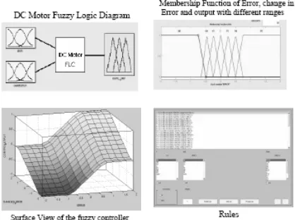
[image:3.612.58.274.549.709.2]is “increment” to the control action is regulated not only by the error’s magnitude but also by the speed and the direction that the error signal flows. The membership functions [14] of these fuzzy variables used by the DC motor and Induction motor fuzzy controllers are shown in figures Fig.3 and the MATLAB Simulink diagrams for DC motor and Induction motor using Fuzzy Logic are shown in Fig. 4 and Fig. 5 respectively.
Similarly Fuzzy logic controller for induction motor has the same structure (same fuzzy input-output variables) and control strategy, but it uses a different membership functions and stightly a different set of rules[15, 16] .The main difference between DC motors and induction motor system is found at different kind of actuations.
Fig.3 The membership functions of fuzzy variables used for the DC motor
V. COMPARISON BETWEEN PID AND FUZZY LOGIC SPEED
CONTROLLERS
In the previous sections, the speed control of Electrical machines is considered using conventional PID controller and Fuzzy Logic controller. The different cases are considered with and without load on the machines.
[image:4.612.317.557.50.240.2]
Fig. 4 MATLAB/Simulink model of the DC Motor using Fuzzy logic Controller.
Fig.5 MATLAB/Simulink model of the Induction Motor using Fuzzy logic Controller
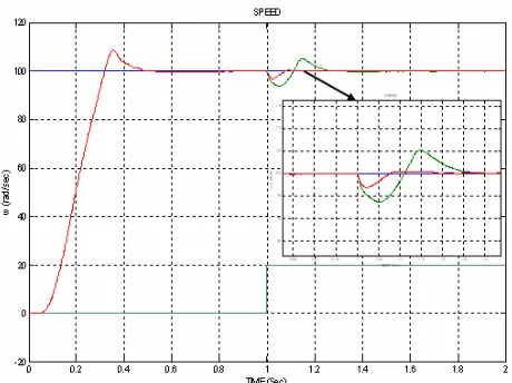
[image:4.612.50.259.235.391.2]The speed control of DC motors using PID and FLC which is designed in MATLAB/Simulink and has been studied with different cases and corresponding results are plotted. The reference speed is defined as 200rad/sec. The simulation results are shown in figure (6), figure (7) for different cases with and without load of 60N-m at 1.5sec and corresponding performance specifications are shown in Table III.
[image:4.612.57.286.538.689.2]0 0.2 0.4 0.6 0.8 1 1.2 1.4 1.6 1.8 2 0 50 100 150 200 250
THE DYANAMIC RESPONSE OF THE DC MOTOR STARTING UNDER NO-LOAD FOR UNIT STEP IN THE REFERENCE SPEED
TIME (Sec) w ( ra d /s e c )
DC MOTOR REFERENCE SPEED DC MOTOR SPEED WITH PID DC MOTOR SPEED WITH FUZZY
Fig. 7 The dynamic response of the DC Motor with PID and
Fuzzy Controller starting under Load with staircase as reference speed
TABLE III The Comparison table of DC Motor Specifications using PID
and Fuzzy logic Controllers
Different types of load
% Maximum peak Over shoot (%Mp)
Setting Time
ts
Steady State error( ess)
IAE
PID
Controller 27.41 1.075 0.5652 01.021 Delay Step input Without load Fuzzy Logic Controller
9.91 1.009 0.4121 1.006
PID Controller 27.41 1.526 0.948138 1.023 Delay Step Input with load Fuzzy Logic Controller
9.91 1.0890 0.198589 1.008
PID
Controller 27.41 0.0750 0.000202 0.021 Step input Without load Fuzzy Logic Controller
9.91 0.0890 0.000175 0.016
PID
Controller 27.41 1.526 0.002687 0.023 Step
input with load
Fuzzy Logic
Controller 9.91 1.5190 0.001704 0.018
PID Controller 46% (1st peak) 45% (2nd peak)
--- --- 0.761 Stair case Without load Fuzzy Logic Controller 12 (1st peak) 18 (2nd peak)
--- --- 0.657
PID Controller 46% (1st peak) 45% (2nd peak) 14% (undershoot due to load)
--- --- 0.761
Stair case with load Fuzzy Logic Controller 12 (1st peak) 18 (2nd peak) 3 (undershoot due to load)
--- --- 0.667
The dynamic model of the Induction motor using fuzzy logic is developed in the MATLAB Simulink using the Induction motor equations. The simulations carried out for
different reference input with load of 20N-m at 1sec and without load and are show in following figure (8), figure (9) and performance specifications are given in table (IV).
Fig. 8 The dynamic response of the Induction Motor with PID
and Fuzzy Controller starting under Load with step as reference speed
Fig. 9 The dynamic response of the Induction Motor with
PID and Fuzzy Controller starting under Load with Trapezoidal as reference speed
TABLE IV The comparison table of Induction motor specification using PID and fuzzy logic
Different types of load % Max imum peak over shoot (%Mp)
Setting Time (sec) ts Steady State error ( ess)
IAE
PID
Controller 8.7117 0.4790 0.196741 20.640 Step
input without
load Fuzzy Logic
Controller 7.8947 0.4310 0.195009 20.617 PID
Controller 8.7117 1.1200 1.0655 20.816 Step
input With
load Fuzzy Logic Controller
7.8947 1.0330 0.874 20.728
PID
Controller ---- ---- ---- 51.227 Trapezoidal
without
load Fuzzy Logic
Controller --- --- --- 50.102
PID
Controller ---- ---- ---- 51.988 Trapezoidal
with
load Fuzzy Logic
[image:5.612.55.271.56.230.2] [image:5.612.315.545.97.269.2] [image:5.612.47.300.321.694.2] [image:5.612.323.558.328.449.2]The simulation results show that the error driven by fuzzy logic controller has shown the best overall performance, as compared to conventional PID controller. This may be due to fact that fuzzy controller search for optioned control input as compared to conventional controllers
The results clearly mention the difference between two methods. The speed control based on Fuzzy logic has better performance than that of conventional PID controller. Fuzzy logic speed control is sometimes seen as the ultimate solution for high performance drives of the next generation.
Finally for a given Kp, Ti, Td, the time domain specifications i.e. Maximum Peak over shoot(MP), settling
time(ts), steady state error (ess)and performance measures IAE
are better as compared to the PID controller.
VI. CONCLUSION
In this paper, a PID controller with fuzzy logic controller based speed control of Electrical machines has been presented. Fuzzy logic controller and PID controllers have been designed for speed control loop. The simulations have been carried out using MATLAB/Simulink Fuzzy Logic toolbox. In order to minimize the real-time computational burden simple membership functions and rules have been used. Since exact system parameters are not required in the implementation of the proposed controller, the performances of the drives system are robust, stable and sensitive to parameters and operating condition variations. In order to prove the superiority of the FLC, a conventional PID controller based Electrical machines DC Motor and Induction Motors has also been simulated and the performance has been investigated at different dynamic operating conditions. It is concluded that the proposed fuzzy
logic controller has shown superior performances like MP, ts,
ess and IAE over the conventional controllers and shows robustness variation of the load torque.
Finally, some conclusions and Future scope of this work are Fuzzy controllers cannot compensate themselves for very large variations of mechanical parameters.
Fuzzy logic controllers are a suitable option to make speed regulation DC motor and AC motors.
The single human based reasoning used on a FLC can be very useful to overcome non-linearities of any kind of plants in a logical way.
It would be necessary to use a more complex intelligent control systems i.e. adaptive fuzzy system, Neuro-Fuzzy systems and genetic algorithms, in order to obtain a better performance on speed control.
REFERENCES
[1] C. Elmas, “Fuzzy Logic Controllers”, Seckin Publishing, April-2003. [2] Applications of Fuzzy Sets Methodologies in Industrial Engirneering.
Evans, Gerald W; Waldemar, K.; Wilhelm, M.R..Amsterdam; New York: Elsevier; 1989
[3] L. A. Zadeh, ‘‘ Fuzzy Sets” Informal Control, vol.8,pp 338-353, 1965 [4] Design of control system for DC drivers. Buxbaum, A.Shierau;
Straughen, A. Berlin; New York: Springer-Verlag 1990.
[5] Chan, C. C., Low Cost Electronic Controlled Variable Speed Reluctance Motors, IEEE Transactions on Industrial Electronics, Vol. IE-34, No. 1. 95-100. February 1987.
[6] Khoei, A.. Hadidi, Kh., Microprocessor Based Closed-Loop Speed Control System For DC Motor Using Power Mosfet. Electronics Circuits and Systems IEEE International Conference ICECS’96, Vol. 2, 1247-1250, 1996.
[7] F. Rahman, ‘Lectures 18 Control of DC-DC Conveners”, Power Electronics. ELEC4240/9240
[8] B.K. Bose, P Electronics and AC Drives, Prentice-Hall, Englewood Cliffs, New Jersey, 1986
[9] L. A. Zadeh, ‘. Outline of a new approach to the analysis complex systems and decision processes” IEEE Trans. Syst.Man Cybem, vol. SMC-3, pp. 28-44, 1973
[10] O. Kaynak. G.Armagan, Otomasyon Magazine. “A new approach for process control: Fuzzy Logic”, July-August 1992.
[11] "Development System for Fuzy Control Systems" (In Spanish), Carlos A.
Hernbndez; J. Manuel Ramirez. MEXICON '9 1, Puebla, Mexic. [12] A fuzzy set Based Control of a Phase Controlled Converter DC Machine
Drive. Gilberto C. D., Bimal K. Bose. IEEE Transactions on Industry Applications, Vol.30 No. 1 January/February 1994.
[13] Fuzzy. Logic Controllers for a DC motor. B. S Thesis. Fonseca,
Joaquin; Hernadez, Sergio. Universidad de las Americas-Puebla. Mexico. 1995.
[14] Fuzzy logic Technology and Applications. Robert MarksII. Technology Update Series. IEEE. 1994.
[15] J.Klir. George, Yuan, Bo. :“Furry Sets and Fuzzy Logic-Theory and
Applications”
[16] Minh Ta-Cao, J.1.Silva Neto, and hoang Le-Huy, “Fuzzy Logic Based Controller for Induction Motor Drives,” CCECE‘96, pp. 63 1-634, 1996.
BIBLIOGRAPHIES
Gaddam Mallesham was born in Bollepally (Vil), Bhongir (Mon),
Nalgonda (Dist.) on 20th August, 1977. He received the B.E degree in
Electrical and Electronics Engineering from University College of Engineering (A), Osmania University, Hyderabad, India in 2000. He received his Masters degree in Control Engineering and Instrumentation from Indian Institute of Technology, Delhi, India in 2002.Since 2002; he has been an Assistant Professor in the Department of Electrical Engineering, University College of Engineering (A), Osmania University, Hyderabad, India. His main interest includes Artificial Intelligence Techniques applied to Electrical Engineering. He was Secretary of IEEE joint chapter of PES/IAS Societies, Hyderabad Section. He has visited Greece and Canada to present technical papers.