Abstract— The purpose of this paper is to clarify the mechanism of how 3D Information Technologies (3D-ITs) are effective on the improvement of quality, cost and delivery (QCD) in the development process of cellular phones. Investigating some real cases of the integral processes among the mechanical design, the electric design and the artistic design in detail, the results of this paper indicated that the use of 3D-ITs improved the quality of the shape design, and that it was effective to reach a middle ground of the shape contradiction and the requirements of the designs. Furthermore, this paper showed the indirect effects of the cellular phone development process and suggested the spillover effect that 3D-ITs caused for the management efficiency of the cellular phone manufacturer.
Index Terms—3D-CAD, 3D Information Technologies, cellular phone development, QCD
I. INTRODUCTION
[image:1.595.46.288.569.622.2]The number of manufacturers that succeeded in improvements of quality, cost and delivery (QCD) by using three dimension information technologies (3D-ITs at the following) in product development processes has been increasing year after year. Therefore, 3D-ITs attract increasing attention from management personnel of manufacturers. Several studies have showed that there is a statistically significant correlation between 3D-ITs and QCD improvement effects [1][2]. However, the introduction of 3D-ITs does not necessarily cause QCD improvement effects. It is also true that a lot of failure cases exist in which QCD can not be improved and they have to return to operation by past 2D-ITs.
Fig 1. All the Processes of Product Developments
One of the features of 3D-ITs is that these tools can be applied to almost all the processes of product developments (Fig 1), while 2D-ITs tools tend to be applied only to a design process for improvement of design efficiency. Therefore, impacts of 3D-ITs on QCD are considerably larger than 2D-ITs. In this paper, the tools of 3D-ITs include 3D-CAD (CAD: Computer aided design) used for mechanical design,
Eitaro MAEDA is with the Engineering Solution Department, Fujitsu Limited. [email protected],
Yasuo KADONO2 is with the Department of Media Science, Tokyo university of technology. [email protected]
CAE (Computer Aided Engineering) used for various kinds of analyses, CG (Computer Graphics) used for artistic design, CAM (Computer Aided Manufacturing) used for prototyping and manufacturing, DMU (Digital Mock-Up) used for the virtual prototyping. These 3D-ITs tools can be used from the upstream to the downstream in the product development process.
The purpose of this paper is to clarify the mechanism of how 3D-ITs are effective on improvement of QCD in the development process of cellular phones.
II. METHODFOR INVESTIGATION
We investigated the case with "A" company (one electric manufacturer in Japan) that has been succeeding in QCD improvement by using 3D-ITs for the cellular phone development. An investigation was conducted by the interview-style and we tried to find out problems and methods of solving them by using 3D-ITs at the each process. Two persons were chosen for the interview. One was involved in 3D-ITs introduction and familiar with the technical side of 3D-ITs and design work. The other was the manager who was in charge of QCD in all the processes.
It should be noted that the cellular phone is to be classified into an "Integral Architecture" product in previous works [3][4]. One of the features of this architecture is that the development should be done while adjusting the interdependency among each part. It is considered that the interdependency is a result that the miniaturization, lightening and solidity are demanded to the cellular phone from market. Therefore, we proceeded with the investigation, focusing attention on problems not only in a single process but also across two or more processes.
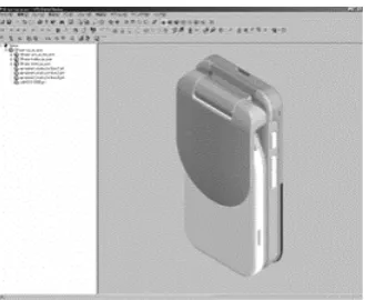
http://jp.fujitsu.com/solutions/plm/casestudies/vps/mobilephone.html Fig 2. Three Dimensional Model
The Effects of 3D Information Technologies
on the Cellular Phone Development Process
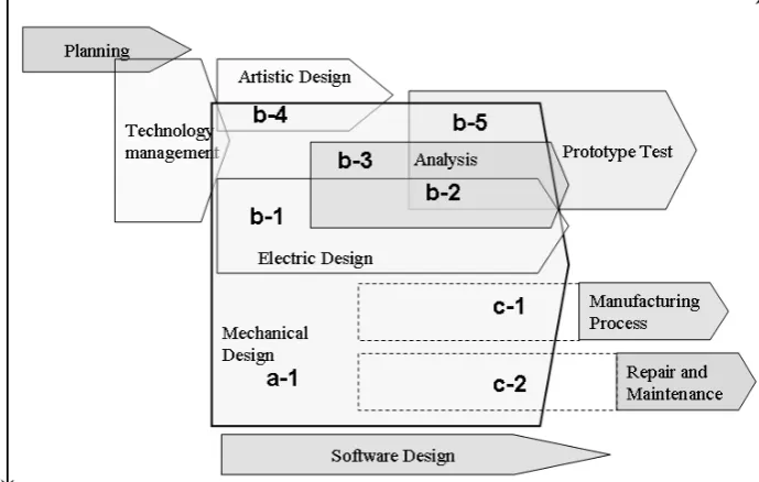
[image:1.595.350.515.607.742.2]Fig 3. All the Processes of the Cellular Phone Development
III. RESULT OF INVESTIGATION
As a result of investigation, this section shows the problems and the methods of solving them by 3D-ITs at each process of the cellular phone development. Fig 3 illustrates all the processes of the cellular phone development, and the vertical axis means the difference of the sections which nearly equals to processes, and the horizontal axis means time. The crossover areas of processes mean the adjustment to solve the problems across two or more processes. These signs in Fig 3, a-1, b-1, b-2, b-3, b-4, b-5, c-1 and c-2 mean the use scene of 3D-ITs.
The problems and the methods of solving them by 3D-ITs in each scene are described as follows.
A. Problems in Single Process and Solutions by 3D-ITs
a-1. In the Mechanical Design Process
As for a fold-type cellular phone, mechanical designers are different in each part (the part of the side of liquid crystal panel, the side of buttons, the joint part, etc.). Therefore, it is necessary to design each part so that the shape contradiction should not occur when these parts are combined. It has become possible for mechanical designer of each part to exchange the design information by three dimension data (3D-data at the following) of 3D-CAD and to adjust the shapes and the sizes between each part.
Moreover, it is necessary to design the parts while avoiding them from interfering mutually when opening and shutting panels. 3D-ITs make it possible to simulate the operation in a virtual space on a computer and to check whether the dynamic interference exists when opening and shutting the panels, and correct the mechanical design if any interference is found.
B. Problems among Parallel Processes and Solutions by 3D-ITs.
b-1.The Mechanical Design Process – the Electric Design Process
As a need for reducing the thickness of cellular phone has been growing, the clearance between the package and the printed-circuit board has become smaller every year. It is necessary to keep an appropriate clearance at the same time as avoiding the interference between the package and the printed-circuit board. The mechanical designers and the electric designers can adjust the distribution of installation clearance by exchanging 3D-data with fulfilling each functional specification.
b-2. The Mechanical Design Process – the Electric Design Process – the Analysis Process – the Prototype Test Process
The positions of the antennas for telephone and television are roughly determined at first by the adjustment between the mechanical design and the electric design in consideration of the structural, spatial restriction. Electric wave signal strength is examined after the antennas are mounted with the prototype model. It was necessary to grope for a more appropriate position if the sensitivity of the electric wave was bad. The electric wave signal strength is analyzed by 3D-ITs and the antenna position of the prototype model is fine-tuned based on the analysis result, and the wave strength is examined again. The repeated adjustments with 3D-ITs between the analysis and the prototype make it possible to find the appropriate antenna position faster and more accurately than only by prototype tests without 3D-ITs in the past.
b-3. The Mechanical Design Process – the Analysis Process
analyzing strength with CAE before the prototype test, and reflecting the analysis results to the mechanism design, the mechanical design time for improvement can be cut.
b-4. The Artistic Design Process – the Mechanical Design Process
The artistic design could be one of the largest factors affecting consumer motivations to buy cellular phones. The mechanical designers should design the mechanical structure without sacrificing the artistic design as much as possible. The mechanical designers can design internal structure while considering the restrictions on shape of the package by getting 3D-data from the artistic designers.
b-5. The Mechanical Design Process – the Prototype Test Process
In the mechanical design process, it is necessary to consider the work procedure of assembling the parts and to confirm the prototype can be assembled without a problem caused by mechanical design mistakes. The mechanical designers and the prototype testers can simulate the procedure of assembling the parts by using DMU, which makes it possible to design easily assembled structure.
In addition, the 3D-data made in the mechanical design is used as the input data to make prototyping models. This enables man-hour cost to be reduced in the prototype test process.
http://jp.fujitsu.com/solutions/plm/casestudies/vps/mobilephone.html Fig 4. Assembly Simulation
C. Problems between Upstream Process and Lower Process and Solutions by 3D-ITs
c-1. The Mechanical Design Process – the Manufacturing Process
In the manufacturing process, it is necessary to reduce the assembling troubles caused by the mechanical design mistakes as well as in the prototype test process. Additionally it is necessary to design the structure that can be efficiently assembled and to shorten the assembly time.
A manufacturability and assembly total time can be
simulated by using 3D-ITs. The mechanical design should be improved if there are any problems in manufacturability even if no problem in mechanical structure.
c-2. The Mechanical Design Process – the Repair and Maintenance Process
It is necessary to advance the consideration on the repair procedure of maintenance and prepare tools at the early stage because those might be needed in short order after the release of new products. In the past without 3D-ITs, the maintainability had not been able to be examined until the prototype model was completed. But now maintenance personnel and mechanical designers make arrangements beforehand in mechanical design process and can examine maintenance tools and how to disassemble it by using 3D-ITs.
IV. RESULT OF ANALYSIS Analysis of Shape Quality Improvement
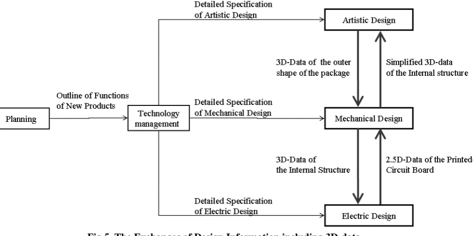
The mechanism of improving quality of shape design is analyzed. Fig 5 shows the exchanges of design information including 3D-data among the artistic design section, the mechanical design section and the electric design section. As a starting point of design information, the planning section transmits the outline of functions of new products to the technology management section. The technology management section resolves the outline of functions to the detailed specification of each design section and transmits it. Each design section starts designing based on each detailed specification, after a certain level of design is done, they exchange the 3D-data.
The artistic design section receives simplified 3D-data of the internal structure from the mechanical design section, and the data are input to CG software or 3D-CAD system used in the artistic design section. The artistic designers design the outer shape of the package while considering installation space of the internal structure.
After that, the mechanical design section receives detailed 3D-data of the outer shape from the artistic design section, and designs an internal structure in more detail. If design changes of outside shape are necessary due to the internal structure, the mechanical design section transmits the design change demand promptly to the artistic design section. 3D-data used as a design change request has a potential to transmit design information accurately and quickly because the change information is clearer and more comprehensible than two dimension drawing.
In the electric design section, a printed-circuit board is designed by using 2.5D-CAD which has two dimension information and height information with regard to the shape expression. In the electric design section, 3D-data of the internal structure is received from the mechanical design section, and the data including internal height is input to electric 2.5D-CAD system used in the electric design section. That enables the electric design to be done while considering the height restriction of internal structure. After that, the mechanical design section receives the detailed 2.5D-data of the printed-circuit board from the electric design section. That enables the internal structure design to be done while considering the height restriction of IC chip on the printed-circuit board.
Fig 5. The Exchanges of Design Information including 3D-data
It should be noted that almost all the exchanges of the 3D-data (or 2.5D-data) are done in the middle of designing. Both the section passing the 3D-data and the section receiving it recognize that the data is uncompleted. On that condition, they input 3D-data each other and concurrently examine the correspondence of shape. It should be also noted that IT systems like PDM (Product Data Management) and E-mailing, etc. are actually used in the 3D-data exchanges though the data exchanges shown in Fig 5 are simplified.
It could be confirmed that 3D-data loop among the artistic design section, the mechanical design section, and the electric design section. By the loop of these 3D-data, the section can design while accurately understanding the shape constraint condition of the other section. In other words, the other sections automatically follow the shape constraint condition of the own section. In the result, the shape contradiction that causes the quality loss can be avoided and the quality concerning shape is improved.
Classification of QCD improvement
Concrete examples of the QCD improvement by 3D-ITs are cited and classified into two types, "Direct improvement of QCD" and "Indirect improvement of QCD" by the difference of how 3D-ITs gives the effect to QCD.(Table 1)
"Direct improvement of QCD" and "Indirect improvement of QCD" have the following features, respectively.
[Direct Improvement of QCD]
3D-ITs are immediate means to solve development tasks and problems of the real world. The QCD improvement is found in the process of using 3D-ITs.
[Indirect Improvement of QCD]
3D-ITs solves development tasks and problems of the 3D model that is design information expressed by three dimensions in a virtual space, and the quality of design information is improved. The QCD improvement is found in lower process of using 3D-ITs.
Method of Evaluating Contribution Level of 3D-ITs to QCD
It is difficult to quantitatively evaluate the contribution level of 3D-ITs in regard to the indirect improvement of QCD because there is a gap of space and time between the scene of using 3D-ITs and the scene in which the effect becomes visible.
Then, we considered a method of evaluating the contribution level by quantitatively measuring "the results in midstream" that means finding and solving the development problems in a virtual space. For instance, as one of the results in midstream, there is the number of the design deficiencies detected at the design process. It is reported that the ratio of the design deficiencies that can be detected only in the prototype test process is about 10-20 percent for all design deficiencies regardless of the category of products, and the remaining 80-90 percent deficiencies can be detected with 3D-ITs. It is thought that comparing the value on actual development with the empirical value in such a report might become one method of evaluating contribution level of 3D-ITs to QCD improvement.
Evaluating Contribution Level of 3D-ITs to QCD through the Whole Development Process
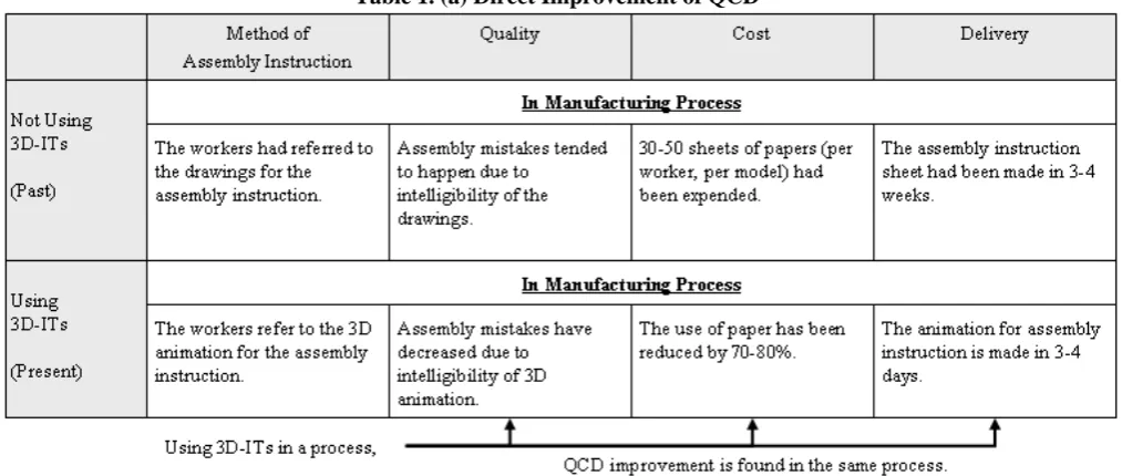
Table 1. (a) Direct Improvement of QCD
[image:5.595.46.553.71.286.2]Table 1. (b) Indirect Improvement of QCD
Table 2. Improvement of QCD (2004 – 2005)
Fig 6. The Transition of the Number of Defects through the Whole Development Process Proceedings of the World Congress on Engineering and Computer Science 2008
[image:5.595.56.549.308.500.2] [image:5.595.130.474.543.613.2][Fact 1]
The following 3D-ITs came to be full-scale used around the year 2004 - 2005.
- 3D-CAD
- Strength Analysis Tool - Electric Wave Analysis Tool - DMU
[Fact 2]
The number of designers had hardly changed around the year 2004 - 2005.
[Fact 3]
The cellular phone had been reducing the thickness and more highly-functional, as an example, the number of pixels of CCD had nearly doubled. Therefore, the development difficulty had been rising around the year 2004 - 2005.
Considering the above facts as the influence for QCD, Fact 2 is a constant factor, and Fact 3 can be a negative factor. The fact that the QCD improvement shown in Table 2 was achieved under such a condition suggests that the introduction of 3D-ITs (Fact 1) greatly contributes to the QCD improvement.
V. DISCUSSION
Spillover effects of 3D-ITs on management efficiency Taking a cellular phone development project as a whole, we consider spillover effects of 3D-ITs on management efficiency. Fig 6 shows the transition curve of the number of defects through the whole development process of a cellular phone, and makes a comparison between using 3D-ITs and not using 3D-ITs based on the result of the interview. The following effects are recognized in the Fig 6.
By using 3D-ITs, [Effect 1]
The peak of the defects curve becomes higher and earlier than not using 3D-ITs because more problems of the development can be easily found and solved in a virtual space.
[Effect 2]
The number of the defects decreases at the time of shipment due to effect 1.
[Effect 3]
The termination of the defects after shipment is earlier due to effect 2.
[Effect 4]
The development period is shortened as a result of effect 3. In addition, it was heard in the interview that the designers could not be allocated to another new model design because design improvement should be continued after shipment if there were any defects in the new model designed by them. Therefore, what we mean by "the development period" should be defined as the period from planning to the termination of defects after shipment. The development period is expressed by Effect 4 in Fig 6, and it can be said that the period is shortened by using 3D-ITs.
Shortening development period makes it possible for manufactures to speed up the release of new product. In fact, the number of new model release in "A" company in a year has actually increased, and it might be said that this fact proves the causal relationship (Effect1- Effect 2- Effect 3- Effect 4) in Fig 6.
Since the early product release have a strong tendency to give sales a boost as for cellular phone market in Japan, all the cellular phone manufactures make large efforts to bring products to market more quickly. Moreover, it is expected that the cost reduction effect by the decrease of defectives becomes larger and larger in "A" company because the cellular phone shipments has been increasing. It is thought that such an increase of sales and cost reduction by using 3D-ITs can bring spillover effects on management efficiency of manufactures.
VI. CONCLUSION
This paper shows one of the mechanisms of improving shape quality by 3D-ITs, using the case that 3D-data loop among the artistic design section, the mechanical design section, and the electric design section on the cellular phone development process. Moreover, we classified the effects of QCD improvement into two types, "direct improvement of QCD" and "indirect improvement of QCD", and suggested a method of evaluating the contribution level by quantitatively measuring "the results in midstream". Additionally, we discussed spillover effects on management efficiency by 3D-ITs.
In order to clarify a clearer mechanism as future task, we should gather quantitative values associated with QCD improvement including the values in the midstream of development and confirm a causal relationship between the values and 3D-ITs contributions.
ACKNOWLEDGMENT
The authors wish to acknowledge the help and advice received from the Graduate School of Engineering Management of Shibaura Institute of Technology.
REFERENCES
[1] Y. Takeda, Y. Aoshima and K. Nobeoka, "Diffusion of 3-D CAD and its Impact on Product Development Processes", Yokohama Journal of Technology Management Studies, Vol. 4 (2005), No. 1, pp.1-12 [2] Y. Park, T. Fujimoto, R. Yoshikawa, P. Hong and T. Abe, MMRC
Discussion Paper, No.161, 2007
[3] T. Fujimoto, Seisan Management Nyumon(Book style), Nikkei Publishing, 2001
[4] T. Fujimoto, A. Takeishi, Y. Aoshima, Business Architecture(Book style), Yuhikaku Publishing, 2001
[5] Fujitsu nippon hatsu monodukuri kenkyukai, "mono wo tukuranai monodukuri(Book style)”, JUSE Press, 2007