Peak-Based Threshold Estimation
IKPEHAI, Augustine, ADEBISI, Bamidele, RABIE, Khaled Maaiuf,
FERNANDO, Michael and WELLS, Andrew
Available from Sheffield Hallam University Research Archive (SHURA) at:
http://shura.shu.ac.uk/23930/
This document is the author deposited version. You are advised to consult the
publisher's version if you wish to cite from it.
Published version
IKPEHAI, Augustine, ADEBISI, Bamidele, RABIE, Khaled Maaiuf, FERNANDO,
Michael and WELLS, Andrew (2017). Energy-Efficient Vector OFDM PLC Systems
with Dynamic Peak-Based Threshold Estimation. IEEE Access, 5, 10723-10733.
Copyright and re-use policy
See
http://shura.shu.ac.uk/information.html
Energy-Efficient Vector OFDM PLC Systems
With Dynamic Peak-Based Threshold Estimation
Augustine Ikpehai,
Graduate Student Member, IEEE,
Bamidele Adebisi,
Senior Member
,
IEEE
, Khaled M.
Rabie,
Member, IEEE,
Michael Fernando and Andrew Wells
, Member, IEEE
Abstract—Power line communication (PLC) has made remarkable strides to become a key enabler of smart grid and its applications. Existing PLC systems are based on orthogonal frequency division multiplexing (OFDM) which has high peak-to-average power ratio (PAPR). This paper presents vector OFDM (VOFDM) with advanced signal processing at the receiver to improve the energy efficiency of the PLC system. Results show that due to its low PAPR properties, VOFDM is less sensitive to impulsive noise and provides a reduction of 5.8 dB in transmit power requirement relative to conventional OFDM. Furthermore, unlike the existing impulsive noise cancellation methods, the adopted signal processing technique also improves the SNR at the receiver by 2.1 dB which further reduces the power requirement of the PLC transceiver. Together, these can simplify design, reduce cost and improve energy efficiency of future PLC transceivers.
Index Terms—Dynamic power threshold-based estimation, energy efficiency, power-line communication (PLC), signal-to-noise ratio (SNR), smart grid, vector OFDM (VOFDM).
I. INTRODUCTION
T
he energy industry is in the centre of unprecedented transformation. As the smart grid evolves and the number of interconnected devices rises, energy efficiency of the enabling communication systems has become a topical issue. Although smart grid will be supported by heterogeneous set of communications systems [1]–[5], one of the main advantages of PLC is that it reduces the cost of communication by using the existing electrical infras-tructure. PLC is a technique for conveying data through the power cables traditionally used for electricity distribution. Generally, PLC systems can be grouped in terms of fre-quency of operation into narrowband (below 500 KHz) and broadband (1.8– 100MHz). However, given that the power cables were not custom-made for communication, they pose severe challenges to data signals. The challenges include frequency selectivity, varying impedance, limited transmit power, multi-pathing, attenuation and non-Gaussian noise [6]. Noise in power line can be grouped into coloured background noise and impulsive noise, with the latter being dominant. These factors degrade system performance in terms of achievable data rate, latency and signal-to-noise ratio (SNR) at the receiver [4].A. Ikpehai, B. Adebisi, K.M. Rabie and M. Fernando are with the School of Electrical Engineering, Manchester Metropolitan University, Manchester, M1 5GD, UK. (e-mails: [email protected]; [email protected]; [email protected]; [email protected]). A. Wells is with Jaguar Land Rover Limited, Warwick CV35 ORR, U.K. (e-mail: [email protected])
This work was supported in part by the Smart In-Building Micro Grid for Energy Management Project through EPSRC under Grant EP/M506758/1 and in part by the Innovate U.K. Project under Grant 101836.
The power amplifier is one of the main energy-consuming components of the transmitters [7], [8]. To achieve maxi-mum power efficiency, the power amplifiers operate in the dynamic range [9]. Energy efficiency and spectral efficiency are two important characteristics of the power amplifier. While spectral efficiency provides the data rate needed by smart grid applications, energy efficiency ensures that optimum number of bits per unit energy is transmitted. Therefore, optimised design of power amplifiers is crucial to the energy efficiency of PLC systems. PLC transceivers consume power in two forms; static and dynamic power. While the the static power is fixed [10], the dynamic power (transmit power) depends on the traffic load. Thus, the energy efficiency challenge can be approached from different perspectives including circuit design as well as signal processing [11].
PLC standards for smart grid applications such as power-line intelligent metering evolution (PRIME), G3-PLC, IEEE 1901.2 and Homeplug Green PHY are based on OFDM. However, the main drawback of OFDM is its high peak-to-average power ratio (PAPR) [12], [13] which reduces the energy efficiency of PLC transmitters. Solving the high PAPR problem requires highly linear power amplifiers which are impracticable because of their high cost and large size. Hence, non-linear power amplifiers are mostly deployed.
Although many studies have reported the low PAPR of vector-OFDM (VOFDM) [14]–[19], they mostly focused on wireless systems. Recently, [20] and [21] investigated VOFDM for non-Gaussian channels, including power lines. The studies found that VOFDM generally provides bet-ter performance than OFDM in PLC. In particular, [20] showed that VOFDM exhibits lower PAPR than conven-tional OFDM. The benefits of low PAPR in PLC systems design include the use of inexpensive, non-linear power am-plifiers as well as energy-efficient transmission. Therefore, energy efficiency is a key consideration in the development of future PLC systems.
This paper exploits the lower PAPR property of VOFDM for more efficient cancellation of impulsive noise at the receiver in order to improve the energy efficiency of PLC systems. In conventional impulsive noise cancellation techniques such as blanking, received signals are nulled when their power exceeds a predefined blanking threshold (Tb). The challenge with this approach is that detailed
noise characteristics, such as signal-to-impulsive-noise ratio (SINR) and the probability of occurrencep, must be known apriori at the receiver in order to accurately determine the optimal value of Tb to be used [22]. Hence, suboptimal
characteristics can degrade performance. To address this issue in VOFDM, this paper employs the dynamic peak-based threshold estimation (DPTE) technique and refers to the new system as VOFDM-DPTE. DPTE relies on the premise that if VOFDM symbol peaks measured at the transmitter are correctly received by the blanker, output SNR can be significantly improved without regard to the short term variation in impulsive noise characteristics, a major weakness of conventional optimal blanking (COB) [23]. In reality, VOFDM symbol peak values could be sent as control information through dedicated channels or contention-free time slots. Therefore, the idea of combining VOFDM with DPTE in this paper is that together, they can significantly improve energy efficiency of the PLC systems. The contribution of this paper is two-fold. First, we deter-mine the dependence of symbol peaks on number of vector block (VBs) in VOFDM systems and the potential impact of the former on transmit power requirement of the power amplifier. The second contribution is the improvement of blanker output SNR using the DPTE technique. Results show that the proposed VOFDM-DPTE method signifi-cantly reduces transmit power and improves SNR at the receiver. The VOFDM-DPTE method can simplify design, reduce cost, improve energy efficiency and electromagnetic conformance of PLC transceivers.
The rest of the paper is organised as follows. In Section II, previous work in energy improvement techniques in PLC is reviewed. System model and the effects of communica-tion networks on smart grid applicacommunica-tions are discussed in Sections III and IV, respectively. Section V presents the DPTE technique in VOFDM while Section VI examines the relationship between signal peaks and transmit power. Section VII analyses the performance of the proposed VOFDM-DPTE technique while Section VIII concludes the paper with highlights of its main results.
II. RELATEDWORK
Compared with other aspects, little work has so far been done on energy efficiency of PLC systems. Energy effi-ciency in PLC can be studied with practical and information theoretic approaches [11]. Early work in this area includes [24] which employed distributed space-time block codes to reduce transmit power requirement in multi-hop PLC networks. Subsequently, [25] investigated power saving using opportunistic decoding in a decode-and-forward (DF) cooperative relaying network while [11] considered energy efficiency as resource allocation problem where the amount of information to be transmitted is the objective and energy is the resource to be minimised. Recently, different aspects of relaying have been investigated with a view to improving energy efficiency of PLC systems [26], [27]. For example, [26] and [28] considered energy harvesting at the relay nodes in a cooperative PLC network. Both studies con-cluded that energy efficiency can be remarkably improved if PLC nodes are capable of harvesting the unwanted high energy of non-Gaussian noise in the power line channel.
In terms of experimental studies, [29] reported that in a DF relay-assisted PLC network, energy efficiency can be improved by optimal time allocation in the relaying scheme. In the same experiment (with typical commercial modems), it was also found that power consumption consists of static
and dynamic (transmit power) components, while the static power is fixed, the transmit power is load-dependent. A recent measurement campaign across six European coun-tries [30], concluded that static power consumption in PLC networks can be reduced by deploying DF multiple-input, multiple-output (MIMO) relays. Further experiments with the MIMO PLC devices [31] revealed that although energy consumption is mostly dominated by static power, dynamic power can be up to about 50% in some modems, with the average being 40%. Within the dynamic power, it was observed that reception consumes less energy than transmis-sion by 20-25%. These works were based on conventional OFDM and from the energy consumption pattern described above, high PAPR of OFDM will be more challenging in the uplink1 in resource-constrained devices such as smart
meters [32]. These are indications that significant energy savings can be achieved by optimising transmitter design in future PLC systems.
To reduce PAPR in OFDM systems, different techniques have been proposed, such as amplitude clipping, tone reservation, partial transmit sequence [33] and selective mapping [13], [34]. However, such techniques may cause signal distortion. On the other hand, various aspects of VOFDM have been studied in wireless systems [35], [36], [37], [38], [14]. Among other outcomes, these studies found and agreed that in frequency-selective channels, VOFDM generally improves system performance [35] relative to OFDM and that the gain increases with the number of VBs. Specifically, studies such as [15]–[19] showed that VOFDM exhibits lower PAPR than conventional OFDM systems. However, to the best of our knowledge, only [20] and [21] have so far investigated VOFDM over power lines.
Furthermore, impulsive noise has been identified as a major performance inhibitor in PLC [4], [23], [39]. To mitigate the harmful effects of impulsive noise on communi-cation signals, a number of techniques have been proposed. The simplest and most common approach is to precede the OFDM demodulator with a memory-less, non-linear preprocessors such as a blanker or clipper [40]–[43]. In line with that, [20] employed conventional blanking and clipping techniques in VOFDM-based PLC systems. The main drawback of these conventional methods is that, in or-der to accurately determine the thresholds, impulsive noise characteristics must be known apriori through detailed mea-surements. During such measurements, transient variations in the impulsive noise characteristics may be undetected. Therefore, this method is prone to blanking errors arising from sub-optimal threshold values and transient variations in impulsive noise characteristics both of which degrade performance severely [23] and can be costly in critical networks such as smart grid.
However, it has been found that DPTE provides the upper bound of blanking in OFDM systems [23], [44]. The principle of DPTE is that if the peak of every VOFDM symbol can be accurately determined and correctly received by the blanker, impulsive noise can be mitigated with-out apriori knowledge of its characteristics. Although the DPTE in OFDM was later enhanced in [45] where partial transmit sequence (PTS) was applied at the transmitter, the additional gain in the output SNR was at the expense
3
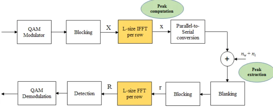
Figure 1: VOFDM-DPTE system diagram with the peak extractor at the receiver
significantly high computational complexity due to several optimisation iterations. Hence, this method is not attractive for resource-constrained devices. Rather, this paper, exploits the inherently low PAPR feature of VOFDM and high receiver SNR gain of DPTE to improve the energy efficiency of PLC transceivers independent of changes in impulsive noise characteristics. The detailed description of DPTE in VOFDM is given in Sec. V.
III. SYSTEMMODEL
The VOFDM system model considered in this work is illustrated in Fig.1 in which the modulated symbols are processed block by block.
VOFDM is a generalization of the conventional OFDM approach. This figure shows the transmitter and receiver sides of the VOFDM system. At the transmitter, the infor-mation bits are first mapped using the quadrature amplitude modulation (QAM) modulation to produce base-band QAM symbols denoted as X. Then a sequence {xn}
N−1
n=0 of N
modulated symbols is column-wise blocked to L vectors each of length M, i.e. N = M L. These vectors will be referred to as VBs. Accordingly, the lth VB can be represented as
xl= [xlM, xlM+1, . . . xlM+M−1]T l= 0,1, . . . , L−1
(1) The transmit VB,xlis reshaped into a matrix ofM rows
andLcolumns such thatN =LM. VOFDM then performs
Lsize inverse fast Fourier transform (IFFT) over theLVBs component-wise as illustrated in Fig. 1. The VOFDM time domain signal after the IFFT can be expressed as
¯
xq =
1
√
L L−1
X
l=0
xlexp
j2πql
L
, q= 0,1, . . . , L−1 (2)
which can also be expressed in a vector form as
¯
xq= [¯xqM,x¯qM+1, . . . ,x¯qM+M−1]T q= 0,1, . . . , L−1.
(3) Similar to conventional OFDM, the vectors{x¯q}Lq=0−1in (3)
are reshaped to a lengthN vector
¯
xT0,x¯T1, . . . ,x¯TL−1
= [¯x0,x¯1, . . . ,x¯N−1]. (4)
Accordingly, the PAPR of this signal is
PAPR=
max|x¯k|2
E h
|x¯k|2
i , k= 0,1, . . . , N−1 (5)
where max(.) is the maximum argument, |.| is the abso-lute value and E[.] denotes the expectation operator. The
VOFDM signal is transmitted over the PLC channel where it is corrupted by the background and impulsive noise. In the time-domain (perfect synchronisation assumed), theqth
received VOFDM symbol vector and the qth received VB
can be respectively expressed as
¯
r= [¯r0,r¯1, . . . ,r¯N−1]
T
(6)
¯
rq = [¯rqM,r¯qM+1, . . . ,¯rqM+M−1]
T
(7) Without loss of generality, it is also assumed that the signal variance is normalised to unity such that σ2
s =
(1/2)E[|xk|2] = 1, σ2w = (1/2)E[|nw|2] and σi2 =
(1/2)E[|ni|
2
]. This paper applies the Bernoulli-Gaussian (BG) model for generating impulsive noise such that [46]
ik =bgk, k= 0,1,2, . . . , N−1 (8)
wheregk is complex white Gaussian noise with mean zero
andbis the Bernoulli process with probabilityPr (b= 1) =
p. Therefore, the probability density function (PDF) of the total noise nt=nw+ni, is given by
Pnt(nt) =
1
X
m=0
pmG nt,0, σm2
=p0G nt,0, σ20
+p1G nt,0, σ12
(9) where nw andni are the background and impulsive noise
components, respectively. It should be noted that x¯k, nw
and ni are assumed to be mutually independent and
E[nwx¯∗k] =E[nix¯∗k] = 0.G(.)is the Gaussian PDF given
as G x, µ, σ2x
= √1
2πσ2 x
exp−(x2−σµ2)2 x
, p0 = (1−p),
p1 = p, σ20 = σw2 and σ21 = σw2 + σ2i. The
vari-ances σ2
w and σ2i denote the background and impulsive
noise powers from which the input SNR and SINR can be respectively computed as SNR = 10log10σs2
σ2 w
and SINR= 10log10σ2s
σ2 i
, whereσs2 is the transmitted signal
variance.
At the receiver, in order to suppress impulsive noise, the blanker is situated before the OFDM demodulator. For each received symbol, the side information is QAM-demodulated, from which the peak estimator extracts the peak value corresponding to the VOFDM symbol and ad-justs the threshold of the blanker accordingly. The received signal r¯k is then passed through the blanker where it is
nulled when it exceeds a certain threshold defined accord-ing to the associated peak value. That way, the blankaccord-ing process adapts to changes in the peak value and determines the blanking threshold independent of the impulsive noise characteristics. In principle, the COB is described as
yk=
(
¯
rk, |r¯k| ≤Tb
0, |r¯k|> Tb
k= 0,1, . . . , N−1 (10) where yk is the output of the nonlinear preprocessor and Tb is the blanking threshold. It is worth noting that careful
selection ofTb is important to ensure optimal performance
of the blanking device. Hence, non-linearity (10) reduces the effect of large received signal values as they are assumed to result from impulsive noise.
Next, we column-wise block {y0, y1, . . . , yN−1} to an
M×L matrix and then perform the fast Fourier transform (FFT) over every row to produce the frequency domain signal. This matrix is then reshaped to produce a1×N-size vector before performing the base-band demodulation and decision. Instead of just COB, DPTE is employed and the performance of the two systems are compared.
IV. EFFECTS OFCOMMUNICATIONNETWORK ON
SMARTGRIDAPPLICATIONS
To illustrate how services within smart grid could be impacted by the PLC network, this section presents the effects of network variability on smart grid applications performance. The underlying communication system in smart grid must seamlessly support automation, sensing and control through a bi-directional exchange of information-this is the promise of smart grid. The PRIME standard defines the physical layer (PHY) and media access control (MAC) specifications for narrowband PLC (NPLC). The PHY features include OFDM (combined with long cyclic prefix of 192µs) to provide delay spread used to combat fre-quency selectivity while the MAC includes automatic repeat request (ARQ), TDMA over CSMA/CA (for contention-free transmission) and DPSK modulation schemes. PRIME supports DBPSK, DQPSK and D8PSK.
Although literature abound in this area, they mostly de-scribe system performance at the PHY in terms of bit error rate (BER) results of the underlying power line channel [47]. In order to maximise the potentials of PLC, it is necessary to assess the smart grid as an integrated system.
Application data size (Bytes)
0 500 1000 1500 2000 2500 3000 3500 4000
Latency(s)/Throughput(kbps)
0 1 2 3 4 5 6 7 8 9 10
Throughput One-way latency
optimal data size
[image:5.595.321.544.62.228.2]impulsive noise
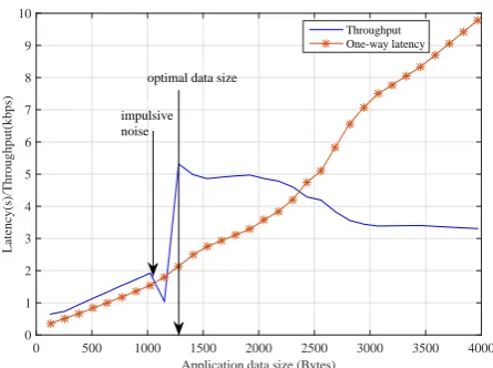
Figure 2: Variation of communication delay with throughput and data size using uncoded OFDM with DBPSK
The simulation in this section is based on PRIME v1.4 standard and includes not only realities such as effects of impulsive noise but also accounts for key network perfor-mance metrics such as latency and throughput in smart grid networks using NS-3 tool. It should be noted that the use of PLC in smart grid is not restricted to NPLC, in practice there are smart meters embedded with BPLC chips and other BPLC-enabled smart grid applications.
Fig. 2 illustrates variation of network performance with application data sizes between a smart meter and a data concentrator (DC) in the low voltage domain. The figure shows that there exists an optimal data size at which the PLC network maximises delivery of packets from smart meters to the DC. However, the first notch observed in the figure can be attributed to transient network impairment due to impulsive noise. This is a classic example of the effect of impulsive noise on data signal which can be explained as follows. The interference arising from the impulsive noise events creates a domino effect in which SINR reduces, followed by PHY data rate reduction. Re-duced PHY data rate forces packet to remain in the transit for longer period during which they could be corrupted, damaged or lost. In fact, this effect is worse in sensitive applications such as smart metering that depend on reliable transport protocols such as transmission control protocol (TCP). For such applications, packet retransmission implies that, successful packets will remain in the buffer until all packets belonging to the same fragment or flow are received before they are passed to the application layer. Although this improves reliability, it does so at the expense of increased latency, higher computational overhead and lower goodput (useful throughput at application layer). From the result in Fig. 2, although the network recovered after the impulsive noise activity, such sporadic events can severely degrade smart grid application performance. Therefore, to provide acceptable quality of service to smart grid applications, effective techniques must be developed to mitigate the harmful effects of impulsive noise on data signals.
V. DYNAMICPEAK-BASEDTHRESHOLDESTIMATION
TECHNIQUE INVOFDM
5
As mentioned in Sec. II, the main challenges of COB are that it requires detailed measurements of impulsive noise characteristics at the receiver and does not sufficiently account for short-term variations in impulsive noise charac-teristics. The optimal blanking threshold in the conventional VOFDM system is determined based on the impulsive noise parameters whereas in the proposed VOFDM-DPTE system, the optimal threshold is obtained by simply using the VOFDM symbol peak values. Instead, DPTE measures symbol peaks at the transmitter and sends the values to the blanker. If the peak estimates are correctly received, blanking can be performed even without the knowledge of the impulsive noise characteristics by the receiver. In this paper, using n symbols and N subcarriers which can be reshaped intoN =M×L, information bits are generated, mapped and blocked into VBs as described in Sec. III. The corresponding VOFDM symbol
x(k) is then generated
and its peak value P eak(k) is determined. Thereafter,
x(k) is transmitted through the PLC channel where it
is contaminated with noise vector n(k) (a composition
of background and impulsive noise) to produce received signal
r(k) .
x(k) ,
n(k) and
r(k) are vectors such
thatk= 0,1,2, ...., n.
In practical systems, P eak(k)can be sent as side infor-mation to the receiver as part of control messages through dedicated channels or contention-free timeslots such as TDMA slots defined in IEEE 1901.1, PRIME v1.4 and other NPLC standards for smart grid. At the receiver, the peak estimator extracts the P eak(k) value associated with thekthsymbol and dynamically adjusts the blanking threshold accordingly. ThekthVOFDM symbol is subjected to blanking operation according to P eak(k). The process is then repeated with COB and compared with DPTE in terms of output SNR. It was shown in [23] that the optimal blanking threshold varies linearly with OFDM symbol peak values. This relationship also exists in VOFDM systems, being a generalised form of OFDM; however, this work exploits the relatively lower symbol peak in VOFDM to simplify impulsive noise detection and cancellation at the receiver.
VI. SIGNALPEAKS ANDTRANSMITPOWER INVOFDM The total power consumed,PT, by a PLC transceiver is
a combination of static and dynamic power. This can be expressed as [29]
PT =P0+P(l) (11)
wherel is the transmitted traffic load in bits/s or packets/s.
P0 is the power consumed (in Watts) in idle state and
is fixed for a given device while P(l) is an increasing function of load (dynamic power). The inevitable choice of OFDM in current PLC systems is at the expense of high PAPR. High PAPR requires highly-linear power amplifier at the transmitter which are bulky, complex and expensive. In the absence of that, high PAPR can cause the power amplifier to be overloaded after which it transits to nonlinear operation (distortion). This phenomenon results in low power efficiency [48], [49] and unwanted electromagnetic emissions [50], [51]. The low power efficiency results in higher amount of energy wasted through heat dissipation [8].
For a conventional OFDM transmitter,PT represents the
sum of the power consumed by the linear power amplifier and the one consumed by other circuit blocks,PC, (usually
very small). In practical systems, energy efficiency of the power amplifier is typically low, for example it is 20-35% in wireless systems [7]. Considering that smart grid will interconnect several millions of devices, energy-efficient communication systems is a key factor in its design. In addition to applications peculiarities, energy efficiency de-pends on variables such as hardware components, the power consumption of the power amplifier, load characteristics and operating frequency [7]. For example, let us consider the Class-A power amplifiers which are the most linear. They consume a constantPDCregardless of the input power [48].
The power amplifier’s energy efficiency is defined as the portion ofPDC delivered to the load and can be expressed
as
ηEE =
Pout,ave PDC
(12) where Pout,ave is the average output power of the power
amplifier, PDC is the DC power consumed by the power
amplifier and PDC >> PC. Under a perfect linear
condi-tion, the energy efficiency approximates to [48]
ηEE =
0.5
P AP R. (13)
Clearly, a reduction of PAPR will result in higher energy efficiency of the power amplifier, hence, timely techniques are needed to reduce PAPR in PLC systems.
As presented in Sec. III, VOFDM uses relatively smaller IFFT size than conventional OFDM. However, since it is practically challenging in multi-carrier systems to accurately determine the peak of every VOFDM symbol, it is common to apply complimentary cumulative distribution function (CCDF) in such estimations. Therefore, this work adopts the CCDF expression (14), which is widely used in the literature. Here, the CCDF is defined as the probability that the peak of VOFDM symbols exceeds a certain valueP eak0
and can be written as
CCDF =1−Pr{Peak≤Peako}= Pr{Peak>Peako}.
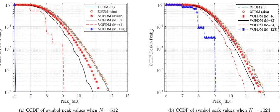
(14) Although (14) is not precise for every symbol, it was shown in [23] that such approximation adequately rep-resents average system performance. It is now necessary to establish the effects of the number of VBs on CCDF of VOFDM symbol peaks compared with typical OFDM. Based on (14), we conducted extensive simulations to determine the CCDF at different peak values for various numbers of VBs. Fig. 3 depicts the variation of VOFDM symbol peak with the number of VBs, where M = 1 is equivalent to conventional OFDM.
Two cases: N = 512 and N = 1024 with various VBs are considered. Fig. 3 shows clearly that provided there are more than one VB, (M >1), VOFDM achieves lower peak values than the typical OFDM system and that the symbol peaks reduce as the number of VBs increases. It is seen that for a given peak valueP eak0, CCDF decreases as the
Peak
o (dB)
6 7 8 9 10 11 12 13
CCDF (Peak > Peak
o
)
10-4 10-3 10-2 10-1
100 OFDM (th)
OFDM (sim) VOFDM (M=16) VOFDM (M=32) VOFDM (M=64) VOFDM (M=128)
(a) CCDF of symbol peak values whenN= 512
Peak
o (dB)
6 7 8 9 10 11 12 13
CCDF (Peak > Peak
o
)
10-4 10-3 10-2 10-1
100 OFDM (th)
OFDM (sim) VOFDM (M=16) VOFDM (M=32) VOFDM (M=64) VOFDM (M=128)
[image:7.595.65.527.73.258.2](b) CCDF of symbol peak values whenN= 1024
Figure 3: CCDF as a function of VOFDM symbol peak values for variousNand VB(M ={16,32,64,128})using105symbols. Analytical and simulated CCDF of the conventional OFDM are also included.
unlike the COB, shifting peak estimation to the transmitter-side relieves the receiver of some computational overhead which can further lessen the effect of transmitter-receiver unbalanced complexity in systems design. Also, for each number of VBs, the performance gap between VOFDM and OFDM closes as the number of subcarriers increases from 512 to 1024. The figure generally indicates that for a fixed
N, as the number of VB increases, VOFDM symbol peaks becomes less likely to be higher than than estimateP eak0.
For example, in Fig. 3b, it is observed that in VOFDM, the symbol peak values are more likely to be higher than 9 dB as the number of VBs decreases from 128. It can generally also be inferred that although the symbol peak value of VOFDM decreases with number of VBs but that comes at the expense of computational complexity. However, ultra-fast chips are readily available at reasonably low cost to ease implementation.
Finally, it is observed in Fig. 3a that by applying VOFDM (M = 128) to QAM modulated signal with N = 512, symbol peak power reduces by about 5.8 dB relative to conventional OFDM. The practical implication is that in PLC-based smart grid, if 20 dBm is required to transmit QAM symbols with OFDM, the transmitter’s power am-plifier needs a maximum of 31.8 dBm to ensure linear operation whereas with VOFDM, maximum of 26.1 dBm is needed. When aggregated over several thousands or millions of PLC nodes, this could yield significant power savings.
VII. OUTPUTSNR PERFORMANCE OFVOFDM-DPTE
SYSTEM
A. Output SNR of the Blanker
This section presents the transmit power savings achiev-able when VOFDM is implemented with DPTE in PLC transceivers. This is done by computing the SNR at the output of the blanking device. However, it is necessary to briefly review the blanker output SNR of COB with various blanking thresholds Tb. In that regard, we investigate the
SNR performance of different VBs in VOFDM and compare the results with OFDM using the COB technique. The blanking procedure is then repeated using the proposed
technique and performance between DPTE and COB is compared. To do this, we consider the SNR at the output of the nonlinear preprocessor which can be computed for the VOFDM as [52]
SN R1=
E h
|K0x¯k|
2i
E h
|yk−K0x¯k|
2i (15)
where K0 is a real constant chosen as K0 =
(1/2)E h
|ykx¯∗k|
2i
.
For OFDM, output SNR is given by
SN R2=
2K2 1
E1−2K12
(16) where
K1=1−
L−1
X
i=0
pi
"
exp
− T
2
b
2 (1 +σ2
i)
+TbΞ
#
(17)
E1= 2 + 2
L−1
X
i=0
pi σi2−Γ
exp
− T
2
b
2 (1 +σ2
i)
(18)
where E1 is the total signal power at the output of the
nonlinear preprocessor,Ξ = Tb
2(1+σ2
i)
exp
− Tb2
2(1+σ2
i)
and
Γ = 1 +Tb2+σ2i [52]. The noise parameters used in this evaluation are input SNR = 25 dB, SINR=−10 dB and
p= 0.01.
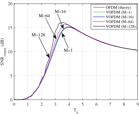
Simulation results of OFDM and VOFDM are obtained using (15). Fig. 4 illustrates the achieveable SNR at the output of the blanker using the COB method. First, it is observed that analytical result agrees with the simu-lation. Within the intermediate region, this figure shows that VOFDM (M = 128) achieves a maximum of about 2 dB SNR improvement over conventional OFDM. The figure also reveals that for all M > 1, VOFDM always outperforms OFDM. However, when the Tb is too low, the
7
T
b
0 1 2 3 4 5 6 7 8 9
SNR
output
(dB)
0 5 10 15 20
OFDM (theory) VOFDM (M=1) VOFDM (M=16) VOFDM (M=64) VOFDM (M=128)
M=1 M=128
[image:8.595.314.538.60.204.2]M=64 M=16
Figure 4: Output SNR performance of the VOFDM system versus the blanking threshold when the input SNR= 25dB, SINR=−10dB andp= 0.01.N= 512,n= 104and 16QAM
SINR (dB)
-40 -35 -30 -25 -20 -15 -10 -5 0
SNR
output
(dB)
21 21.5 22 22.5 23 23.5 24 24.5 25
[image:8.595.62.289.63.249.2]OFDM-COB OFDM-DPTE VOFDM-COB (M=16) VOFDM-DPTE (M=16)
Figure 5: SNR performance of DPTE and COB in VOFDM system with input SNR= 25dB,p= 0.001,n=5*104andN= 256
during blanking. Conversely, when Tb is too high, some
of the impulsive noise samples push through the system undetected, thereby degrading the SNR at the receiver. It is further observed at these extreme blanking thresholds that OFDM achieves the same performance as VOFDM. Between these extremes, there exists a value ofTb which
maximises the output SNR of the blanker. Next, we compare the SNR performance of DPTE and conventional blanking techniques.
Fig. 5 compares the output SNR performance between DPTE and COB in OFDM and VOFDM. It is clear that DPTE outperforms COB. This result demonstrates that if a certain QAM modulated symbol sequence of length N
signal is blanked using the DPTE technique, even with OFDM and 16 VBs, the output SNR can be improved by 1.1 dB in each case relative to COB. The figure further shows that at extreme values (very low and very high) of SINRs, the output SNR is not affected by the number of VBs in VOFDM, as it becomes identical for both systems. This is logical because at one extreme, when SINR is very high, the system tends to behave as if impulsive noise does not exist, yielding maximum SNR. Given that amplitude of the affected symbols is typically higher than the average
SINR (dB)
-40 -35 -30 -25 -20 -15 -10 -5 0
SNR
output
(dB)
22 22.5 23 23.5 24 24.5 25
OFDM-DPTE VOFDM-DPTE (M=16) VOFDM-DPTE (M=32) VOFDM-DPTE (M=64) VOFDM-DPTE (M=128)
Figure 6: Blanker output SNR as a function of SINR of the VOFDM-DPTE with parameters N = 256, n= 104 symbols in 16QAM, p= 0.001and the input SNR = 25 dB.
amplitude of symbols, at the other extreme, when SINR is very low, impulsive noise samples can be more easily detected and cancelled which also results in maximum SNR. Following from Fig. 5, the output SNR is expected to improve as the number of VBs increases. That is presented and analysed in the remaining part of this section.
Fig. 6 presents the variation of the output SNR with SINR for different numbers of VBs. It is obvious from the results that the output SNR performance improves with the number of VBs. This result underscores the earlier observation in Fig. 5. For example, at M=128, DPTE can increase output SNR by about 0.6 dB compared with the case whenM=16.
B. Comparative SNR performance for various impulsive noise cases
In a smart grid where several thousands or millions of heterogeneous devices with different operational character-istics are interconnected, the probability of impulsive noise can be significantly high. Here we investigate the SNR performance of DPTE and COB in different impulsive noise conditions.
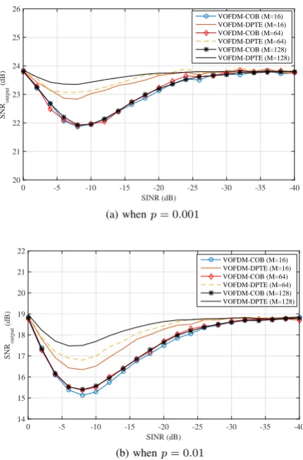
Fig. 7 compares the output SNR of DPTE with COB in a VOFDM system under various channel conditions based on impulsive noise events. It is observed that for all VBs, DPTE consistently outperforms COB. It can also be seen that the output SNR improves with the number of VBs such that the peak SNR is achieved when M=128, yielding a maximum SNR improvement of about 2.1 dB over COB. Finally, the figure reveals that at extreme SINRs, the output SNR is independent of the number of VBs. The functional consequence of these results is that unlike OFDM (M = 1), the existence of M= {16,32,64,128. . . } in VOFDM provides significant flexibility in system design as complexity can now be matched with performance without loosing the fundamental benefits of OFDM as a multi-carrier system.
C. DPTE Gain Relative to Coventional Blanking
This section presents the SNR gain of DPTE technique relative to COB for different probabilities of impulsive noise. The relative gain GRelative is therefore defined as
GRelative= 10log10
SN RDP T E
SN RCOB
[image:8.595.61.296.309.456.2]
SINR (dB)
-40 -35 -30 -25 -20 -15 -10 -5 0
SNR
output
(dB)
20 21 22 23 24 25 26
VOFDM-COB (M=16) VOFDM-DPTE (M=16) VOFDM-COB (M=64) VOFDM-DPTE (M=64) VOFDM-COB (M=128) VOFDM-DPTE (M=128)
(a) whenp= 0.001
SINR (dB)
-40 -35 -30 -25 -20 -15 -10 -5 0
SNR
output
(dB)
14 15 16 17 18 19 20 21 22
VOFDM-COB (M=16) VOFDM-DPTE (M=16) VOFDM-COB (M=64) VOFDM-DPTE (M=64) VOFDM-COB (M=128) VOFDM-DPTE (M=128)
[image:9.595.67.282.94.420.2](b) whenp= 0.01
Figure 7: Comparative SNR performance of DPTE and COB in var-ious impulsive noise conditions usingp={0.001,0.01}, SNR=25, N= 256, 16QAM andn= 104
SINR (dB)
-40 -35 -30 -25 -20 -15 -10 -5 0
Relative Gain (dB)
0 0.5 1 1.5 2
2.5 SNR Gain (p=0.001)SNR Gain (p=0.01)
SNR Gain (p=0.02) SNR Gain (p=0.05)
Figure 8: Relative SNR gain of VOFDM-DPTE over COB for different impulsive noise probabilities forN = 256and M = 64
at input SNR= 30dB,p= 0.05,n= 104and 16QAM
The result is illustrated in Fig.8. It is clear that, given the same channel conditions, DPTE always achieves higher output SNR relative to COB. It is also observed that, the relative SNR gain increases as p decreases. For example, atp= 0.001 a relative gain of 2 dB is achieved, but when
p increases to 0.05, the maximum gain reduces to about 0.74 dB. In both cases of N = 256 and N = 512, it is obvious that, for all values of p, there is a certain value of SINR at which GRelative is highest, in this figure, that
value is -10dB. Finally, the mere fact thatGRelative>0in
all cases clearly indicates that DPTE always performs better than COB, even when the peak estimates are corrupted by impulsive noise. This can be explained by the fact that DPTE dynamically tunes the blanking threshold, in the event that the side information is corrupted by impulsive noise, only a very small fraction of the peak values are affected whereas short-term variations in impulsive noise behavior may consistently be undetected in COB. Hence, given the same transmit power on both systems, DPTE is more energy efficient.
VIII. CONCLUSION
Energy-efficient communication is crucial in smart grid. However, the high PAPR in conventional OFDM affects the energy efficiency and cost of PLC systems which is more pronounced in smart grid due to its scale. To improve energy efficiency in PLC systems, this paper has shown that existence of VBs in VOFDM offers variable IFFT size which introduces new design choices to match complexity with energy efficiency. Furthermore, impulsive noise is one of the dominant challenges in PLC systems and COB is the simplest and widely used method for its cancellation. To suppress impulsive noise at the receiver, DPTE has been applied in this work. By exploiting the low PAPR and high SNR properties of VOFDM and DPTE respectively, this paper demonstrated that transmit power can be reduced by about 5.8 dB while the output SNR of the blanker is increased by 2.1 dB relative to conventional OFDM. When aggregated over several thousands or millions of nodes in a neighbourhood area network for example, this can yield massive savings in power requirements. It was observed that VOFDM performance gains came at the expense of computational complexity, however, ultra-fast, inexpensive chips are readily available to ease implementation. Hence, this is a reasonable sacrifice.
REFERENCES
[1] H. Farhangi, “The path of the smart grid,”IEEE power and energy mag., vol. 8, no. 1, 2010.
[2] S. Mudriievskyi, I. Tsokalo, A. Haidine, B. Adebisi, and R. Lehnert, “Performance evaluation of MAC backoff algorithm in narrowband PLC,” in IEEE Int. Conf. on Smart Grid Commun. (SmartGrid-Comm), 2011, pp. 108–113.
[3] S. Galli, A. Scaglione, and Z. Wang, “For the grid and through the grid: The role of power line communications in the smart grid,”
Proceedings of the IEEE, vol. 99, no. 6, pp. 998–1027, 2011. [4] A. Ikpehai, B. Adebisi, K. M. Rabie, R. Haggar, and M. Baker,
“Experimental study of 6LoPLC for home energy management systems,”MDPI Energies, vol. 9, no. 12, p. 1046, 2016.
[image:9.595.65.282.544.721.2]9
[6] M. Rozman, A. Ikpehai, B. Adebisi, and K. M. Rabie, “Channel characterisation of cooperative relaying power line communication systems,” inProc. IEEE Int. Symp. on Commun. Systems, Networks and Digital Signal Process., 2016, pp. 1–5.
[7] J. Joung, C. K. Ho, K. Adachi, and S. Sun, “A survey on power-amplifier-centric techniques for spectrum-and energy-efficient wire-less communications,”IEEE Commun. Surveys & Tutorials, vol. 17, no. 1, pp. 315–333, 2015.
[8] H. Ochiai, “An analysis of band-limited communication systems from amplifier efficiency and distortion perspective,” IEEE Trans. on Commun., vol. 61, no. 4, pp. 1460–1472, 2013.
[9] L. Guan and A. Zhu, “Green communications: Digital predistortion for wideband RF power amplifiers,”IEEE Microwave Mag., vol. 15, no. 7, pp. 84–99, 2014.
[10] W. Bakkali, P. Pagani, and T. Chonavel, “Energy efficiency per-formance of relay-assisted power-line communication networks,” in
Proc. IEEE Consumer Commun. and Networking Conf., 2015, pp. 525–530.
[11] J.-Y. Baudais, A. M. Tonello, and A. Hamini, “Energy efficient resource allocation for quantity of information delivery in parallel channels,”Trans. Emerging Telecommun. Technol., 2014.
[12] K. Rabie, E. Alsusa, A. Familua, and L. Cheng, “Constant envelope OFDM transmission over impulsive noise power-line communication channels,” inProc. IEEE Int. Symp. Power Lines Commun. (ISPLC), Mar. 2015, pp. 13–18.
[13] J. S. Lee, H. M. Oh, J. T. Kim, and J. Y. Kim, “Performance of scaled SLM for PAPR reduction of OFDM signal in PLC channels,” in Proc. IEEE Int. Symp. Power Lines Commun. (ISPLC), March 2009, pp. 166–170.
[14] J. Han and G. Leus, “Space-time and space-frequency block coded Vector OFDM modulation,”IEEE Commun. Letters, vol. 21, no. 1, pp. 204–207, 2017.
[15] I. Ngebani, Y. Li, X.-G. Xia, H. S. Ahmed, and M. Zhao, “Analysis of phase noise in vector OFDM systems,” in Proc. IEEE Global Commun. Conf. (GLOBECOM), Dec. 2013, pp. 3602–3607. [16] W. Zhou, L. Fan, and H. Chen, “Vector orthogonal frequency division
multiplexing system over fast fading channels,”IET Commun., vol. 8, no. 13, pp. 2322–2335, Sept. 2014.
[17] Y. Li, I. Ngebani, X.-G. Xia, and A. Høst-Madsen, “On performance of vector OFDM with linear receivers,”IEEE Trans. Signal Process., vol. 60, no. 10, pp. 5268–5280, Nov. 2012.
[18] P. Cheng, M. Tao, Y. Xiao, and W. Zhang, “V-OFDM: On perfor-mance limits over multi-path rayleigh fading channels,”IEEE Trans. Commun., vol. 59, no. 7, pp. 1878–1892, Jul. 2011.
[19] I. Ngebani, Y. Li, X.-G. Xia, and M. Zhao, “EM-based phase noise estimation in vector OFDM systems using linear MMSE receivers,”
IEEE Trans. Veh. Technol., vol. 65, no. 1, pp. 110–122, Jan. 2016. [20] B. Adebisi, K. M. Rabie, A. Ikpehai, C. Soltanpur, and A. Wells,
“Vector ofdm transmission over non-gaussian power line communi-cation channels,”IEEE Systems Journal, 2017.
[21] C. Soltanpur, K. Rabie, B. Adebisi, and A. Wells, “Masreliez-equalized VOFDM in non-Gaussian channels:power line communi-cation systems,”IEEE Systems Journal, 2017.
[22] K. M. Rabie and E. Alsusa, “Improving blanking/clipping based impulsive noise mitigation over powerline channels,” inIEEE 24th Int. Symp. on Personal Indoor and Mobile Radio Communications (PIMRC). IEEE, 2013, pp. 3413–3417.
[23] E. Alsusa and K. M. Rabie, “Dynamic peak-based threshold esti-mation method for mitigating impulsive noise in power-line com-munication systems,” IEEE Trans. Power Del., vol. 28, no. 4, pp. 2201–2208, 2013.
[24] L. Lampe, R. Schober, and S. Yiu, “Distributed space-time coding for multihop transmission in power line communication networks,”
IEEE Journal Sel. Areas Commun., vol. 24, no. 7, pp. 1389–1400, 2006.
[25] S. D’Alessandro, A. M. Tonello, and F. Versolatto, “Power savings with opportunistic decode and forward over in-home PLC networks,” in Proc. IEEE Int. Symp. on Power Line Commun. and Its Appl. (ISPLC), 2011, pp. 176–181.
[26] K. M. Rabie, B. Adebisi, A. M. Tonello, and G. Nauryzbayev, “For more energy-efficient dual-hop DF relaying power-line communica-tion systems,”IEEE Systems Journal, 2017.
[27] K. M. Rabie and B. Adebisi, “Enhanced Amplify-and-Forward Relaying in non-Gaussian PLC networks,”IEEE Access, 2017. [28] K. M. Rabie, B. Adebisi, and A. Salem, “Improving energy efficiency
in dual-hop cooperative PLC relaying systems,” inProc. IEEE Int. Symp. on Power Line Commun. and its Appl. (ISPLC), 2016, pp. 196–200.
[29] W. Bakkali, M. Tlich, P. Pagani, and T. Chonavel, “A measurement-based model of energy consumption for plc modems,” inProc. IEEE Int. Symp. on Power Line Commun. and its Appl. (ISPLC), 2014, pp. 42–46.
[30] W. Bakkali, P. Pagani, T. Chonavel, and A. M. Tonello, “Energy efficiency performance of decode and forward MIMO relay PLC systems,” inProc. IEEE Int. Symp. on Power Line Commun. and its Appl. (ISPLC), 2016, pp. 201–205.
[31] W. Bakkali, P. Pagani, and T. Chonavel, “Experimental analysis and modeling of energy consumption behaviour for MIMO PLC modems,” in Proc. IEEE Global Commun. Conf. (GLOBECOM), 2015, pp. 1–5.
[32] T. W. D. B. M.Dohler, T. Watteyne, “Routing requirements
for urban low-power and lossy networks,” IETF RFC5548
https://tools.ietf.org/html/rfc5548 (accessed on 10 Feb. 2017), 2009. [33] T. T. Nguyen and L. Lampe, “On partial transmit sequences for PAR reduction in OFDM systems,”IEEE Trans. Wireless Commun., vol. 7, no. 2, pp. 746–755, Feb. 2008.
[34] K. M. Rabie and E. Alsusa, “Efficient SLM based impulsive noise reduction in powerline OFDM communication systems,” in Proc. IEEE Global Commun. Conf. (GLOBECOM), Dec. 2013, pp. 2915– 2920.
[35] P. Cheng, M. Tao, Y. Xiao, and W. Zhang, “V-OFDM: On perfor-mance limits over multi-path rayleigh fading channels,”IEEE Trans. Commun., vol. 59, no. 7, pp. 1878–1892, 2011.
[36] H. Zhang, X.-G. Xia, L. J. Cimini, and P. C. Ching, “Synchronization techniques and guard-band-configuration scheme for single-antenna vector-OFDM systems,” IEEE Trans. Wireless Commun., vol. 4, no. 5, pp. 2454–2464, 2005.
[37] H. Zhang, X.-G. Xia, Q. Zhang, and W. Zhu, “Precoded OFDM with adaptive vector channel allocation for scalable video transmis-sion over frequency-selective fading channels,”IEEE Trans. mobile comput., vol. 99, no. 2, pp. 132–142, 2002.
[38] H. Zhang and X.-G. Xia, “Iterative decoding and demodulation for single-antenna vector OFDM systems,”IEEE trans. on veh. technol., vol. 55, no. 4, pp. 1447–1454, 2006.
[39] B. Adebisi, S. Ali, and B. Honary, “Space-frequency and space-time-frequency M3FSK for indoor multiwire communications,”IEEE Trans. on Power Del., vol. 24, no. 4, pp. 2361–2367, 2009. [40] S. V. Zhidkov, “Performance analysis and optimization of OFDM
receiver with blanking nonlinearity in impulsive noise environment,”
IEEE Trans. on Veh. Technol., vol. 55, no. 1, pp. 234–242, 2006. [41] ——, “On the analysis of OFDM receiver with blanking nonlinearity
in impulsive noise channels,” in Proc. Int. Symp. Intell. Signal Process. Commun. Syst., Nov. 2004, pp. 492–496.
[42] K. Vastola, “Threshold detection in narrow-band non-gaussian noise,”
IEEE Trans. on Commun., vol. 32, no. 2, pp. 134–139, 1984. [43] R. Ingram, “Performance of the locally optimum threshold receiver
and several suboptimal nonlinear receivers for ELF noise,”IEEE Journal of oceanic engineering, vol. 9, no. 3, pp. 202–208, 1984. [44] K. M. Rabie and E. Alsusa, “Quantized peak-based impulsive noise
blanking in power-line communications,”IEEE Trans. Power Del., vol. 29, no. 4, pp. 1630–1638, 2014.
[45] K. Rabie and E. Alsusa, “Improved DPTE technique for impulsive noise mitigation over power-line communication channels,”Elsevier AEU-Int. Journal of Electronics and Commun., vol. 69, no. 12, pp. 1847–1853, 2015.
[46] M. Ghosh, “Analysis of the effect of impulse noise on multicarrier and single carrier QAM systems,”IEEE Trans. Commun., vol. 44, no. 2, pp. 145–147, Feb. 1996.
[47] J. Matanza, S. Kiliccote, S. Alexandres, and C. Rodríguez-Morcillo, “Simulation of low-voltage narrow-band power line communication networks to propagate openADR signals,”IEEE Journal of Commun. and Networks, vol. 17, no. 6, pp. 656–664, 2015.
[48] R. J. Baxley and G. T. Zhou, “Power savings analysis of peak-to-average power ratio in OFDM,”IEEE Trans. on Consumer Electron-ics, vol. 50, no. 3, pp. 792–798, 2004.
[49] T. Jiang, C. Li, and C. Ni, “Effect of PAPR reduction on spectrum and energy efficiencies in OFDM systems with class-A HPA over AWGN channel,”IEEE Trans. on broadcasting, vol. 59, no. 3, pp. 513–519, 2013.
[50] B. Adebisi and B. Honary, “Comparisons of indoor PLC emissions measurement results and regulation standards,” inIEEE International Symposium on Power Line Communications and Its Applications. IEEE, 2006, pp. 319–324.
[51] B. Adebisi, J. Stott, and B. Honary, “Experimental study of the interference caused by PLC transmission on HF bands,” 2006. [52] S. V. Zhidkov, “Analysis and comparison of several simple
Augustine Ikpehai (GSM’14), obtained M.Sc. degree in mobile and personal radio commu-nication engineering from Lancaster University, UK in 2005. Prior to that, he received B.Sc in Physics from University of Ibadan, Nigeria. Between 2006 and 2014, Augustine worked as Network Engineer with IT-Engineering depart-ment, Zenith Bank Plc, Nigeria. Augustine has extensive industry experience in IP network de-sign, implementation and optimisation; backed with many professional certifications in Cisco and Juniper Networks. He is currently with division of Electrical/Electronic Engineering, Manchester Metropolitan University, UK where he is working towards Ph.D. degree in smart grid communication. His research interests include communications systems modelling, smart home, power line com-munication and energy optimisation in smart grid and other cyber-physical systems. He is a recipient of MMU Knowledge Exchange Project award and the Outstanding Knowledge Exchange award, both in 2016.
Bamidele Adebisi(M’06, SM’15) received his Master’s degree in advanced mobile communi-cation engineering and Ph.D. in communicommuni-cation systems from Lancaster University, UK, in 2003 and 2009, respectively. Before that, he obtained a Bachelor’s degree in electrical engineering from Ahmadu Bello University, Zaria, Nigeria, in 1999. He was a senior research associate in the School of Computing and Communication, Lancaster University between 2005 and 2012. He joined Metropolitan University, Manchester in 2012 where he is currently a Reader in Electrical and Electronic Engineering. He has worked on several commercial and government projects focusing on various aspects of wireline and wireless commu-nications. He is particularly interested in Research and Development of communication technologies for electrical energy monitoring/management, transport, water, critical infrastructures protection, home automation, IoTs and Cyber Physical Systems. He has several publications and a patent in the research area of data communications over power line networks and smart grid. He is a member of IET and a senior member of IEEE.
Khaled Maaiuf Rabie(SM’12, M’15), received the B.Sc. degree (with Hons.) from University of Tripoli, Libya, and the M.Sc. degree (with Hons.) from the university of Manchester, UK, in 2008 and 2010, respectively. In 2011, he joined the university of Manchester where he worked as part-time staff and received his Ph.D. degree in Communication Engineering in 2015. He is currently a Postdoctoral Research Associate at Manchester Metropolitan University (MMU), Manchester, UK. His research interests include signal processing and analysis of power-line and wireless communication networks. Dr. Rabie received several awards, both nationally and interna-tionally, including the Agilent Technologies’ best M.Sc. student award, the Manchester Doctoral College Ph.D. scholarship and the MMU Outstanding Knowledge Exchange Project award of 2016. He was also the recipient of the best student paper award at the IEEE International Symposium on Power Line Communications and its applications (ISPLC) in 2015, Texas, US.
Michael Fernando received his MSc in Opto-electronic and communication systems and his PhD in Microwave Imaging from Northumbria University, UK, in 2005 and 2012, respectively. Before that, he obtained his Bachelor’s degree in Electronics and Communication Engineering from Madurai Kamraj University, India, in 2003. He currently holds the position of Principal Lec-turer, Electrical and Electronic Engineering at Manchester Metropolitan University (MMU). He is a Chartered Engineer CEng, with IET. Mike’s current research interests include microwave holography, wireless power transfer, power line communication, medical imaging applications, con-cealed weapon detection and late time response system. Mike has published in many journals and conferences and delivered keynote speeches in various conferences and institutions.