Localized interlayer complexes in heterobilayer transition metal dichalcogenides
M. Danovich,1 D. A. Ruiz-Tijerina,1 R. J. Hunt,2 M. Szyniszewski,2 N. D. Drummond,2 and V. I. Fal’ko11
National Graphene Institute, University of Manchester, Booth St E, Manchester M13 9PL, United Kingdom 2
Department of Physics, Lancaster University, Lancaster LA1 4YB, United Kingdom
(Dated: June 4, 2018)
We present theoretical results for the radiative rates and doping-dependent photoluminescence spectrum of interlayer excitonic complexes localized by donor impurities in MoSe2/WSe2twisted
het-erobilayers, supported by quantum Monte Carlo calculations of binding energies and wave-function overlap integrals. For closely aligned layers, radiative decay is made possible by the momentum spread of the localized complexes’ wave functions, resulting in radiative rates of a fewµs−1. For strongly misaligned layers, the short-range interaction between the carriers and impurity provides a finite radiative rate with a strong asymptotic twist angle dependence ∝ θ−8. Finally,
phonon-assisted recombination is considered, with emission of optical phonons in both layers resulting in additional, weaker emission lines, red shifted by the phonon energy.
I. INTRODUCTION
Recent advances in the study of two-dimensional (2D) materials have allowed the realization of van der Waals (vdW) heterostructures consisting of vertically stacked 2D layers, resulting in unique properties and potential novel device applications1–5. The layers forming these heterostructures are only weakly bound by vdW forces, and largely retain their individual characteristic proper-ties. Yet, the weak interlayer coupling allows the different properties of various 2D materials to be combined.
One such family of vdW heterostructures are hetero-bilayers of 2D transition metal dichalcogenides (TMDs), which have attracted much interest due to their unique optical properties, dominated by strongly bound exci-tonic complexes6,7 and spin- and valley-dependent opti-cal selection rules8,9. The most commonly studied het-erobilayers are of the form MoX2/WX2, with X = S or Se, due to their type-II (staggered) band alignment, in which the lowest conduction-band (CB) edge and the highest valence band (VB) edge are spatially confined to different layers10,11. In this configuration, electrostatic interactions between electrons and holes across the het-erostructure result in the formation of interlayer exci-tonic complexes, whose constituent carriers are spatially separated in the out-of-plane direction. Optical signa-tures of these interlayer complexes have been reported in photoluminescence (PL) experiments12–14, where new PL peaks are observed in the spectra of bilayer regions. These signatures appear at energies below the monolayer photoemission lines, due to the smaller interlayer band gap in the staggered band configuration.
Photoemission by free interlayer excitons is limited by the relative interlayer angle θ and the incommen-surability of the two TMD lattices δ, resulting in a momentum-space mismatch ∆K ≈ K√δ2+θ2 between the conduction- and valence-band edges, as shown in Fig. 2(b). Radiative recombination becomes effectively in-direct, and thus suppressed by energy and momentum conservation15. These constraints are relaxed when in-terlayer excitons and larger excitonic complexes localize about charged defects, such as donor ions, which are commonly observed as dopants in real samples.
For-mation of these complexes is favored by the long inter-layer exciton lifetimes resulting from the spatial separa-tion of their carriers, which allow for their localizasepara-tion by the deep potential wells provided by the ions. The spread in momentum space of these localized complexes opens the possibility for a finite radiative matrix element
M ∝R
d2r ei∆K·rΨ(r), where Ψ(r) is the envelope wave
function of the complex.
In this paper, we provide a theory for the radiative recombination of localized interlayer complexes in TMD heterostructures of the form MoX2/WX2, where the car-riers are bound to a donor ion in the MoX2layer. Focus-ing specifically on MoSe2/WSe2encapsulated in hexago-nal boron nitride (hBN), we use variatiohexago-nal and diffusion quantum Monte Carlo (VMC and DMC) simulations16,17 to evaluate the binding energies and wave-function over-lap integrals of complexes involving one or two holes in the WSe2 layer and up to four electrons in the MoSe2 layer, accounting for bilayer and encapsulation screening effects. We discuss the energetics and stability of these complexes based on their binding energies, and the ro-bustness of our results against uncertainty in model pa-rameters, such as the carrier effective masses and screen-ing lengths.
Motivated by the binding energies obtained from our quantum Monte Carlo (QMC) calculations and PL experiments18, we study the radiative recombination of the two simplest complexes consisting of MoX2electrons and a single WX2 hole bound to an impurity center: a donor ion and an exciton (D0
c0hv), and a donor-bound
trion (D0
c0Xvc0). We predict the qualitative PL spectrum
from these complexes for closely aligned TMD hetero-bilayers, and estimate the asymptotic behavior of their PL signals in the regime of strong misalignment based on general kinematics and perturbation theory. Our re-sults indicate a rapid decay of the PL signals from the most relevant donor-bound interlayer complexes with the interlayer twist angle (θ), resulting from the asymptotic behavior Γ ∼ θ−8 of the radiative rates at strong mis-alignment. As a consequence, we expect that optical sig-natures from these complexes can be detected only in closely aligned crystals. Our results provide a new per-spective for the interpretation of recently reported
2
1.2 1.3 1.4 1.5
0.00 0.05 0.10 0.15 0.20
1.2 1.3 1.4 1.5
0.0 0.2 0.4 0.6 0.8 1.0
✓
[ ]
(b)
[
µ
s
1]
(a)
(c)
I
[a
.
u
.
]
I
[a
.
u
.
]
E[eV]
E[eV]
Xvc0
<latexit sha1_base64="B/oBOuU5TBmWJlChcC+Pq6BLn5U=">AAAB7XicbVBNS8NAEJ34WetX1aOXxSJ6KokI6q3oxWMFYwttKJvtpl262YTdSaGE/ggvHlS8+n+8+W/ctjlo64OBx3szzMwLUykMuu63s7K6tr6xWdoqb+/s7u1XDg6fTJJpxn2WyES3Qmq4FIr7KFDyVqo5jUPJm+Hwbuo3R1wbkahHHKc8iGlfiUgwilZqtrr5iJ1NupWqW3NnIMvEK0gVCjS6la9OL2FZzBUySY1pe26KQU41Cib5pNzJDE8pG9I+b1uqaMxNkM/OnZBTq/RIlGhbCslM/T2R09iYcRzazpjiwCx6U/E/r51hdB3kQqUZcsXmi6JMEkzI9HfSE5ozlGNLKNPC3krYgGrK0CZUtiF4iy8vE/+idlNzHy6r9dsijRIcwwmcgwdXUId7aIAPDIbwDK/w5qTOi/PufMxbV5xi5gj+wPn8AZNEj0I=</latexit>
<latexit sha1_base64="B/oBOuU5TBmWJlChcC+Pq6BLn5U=">AAAB7XicbVBNS8NAEJ34WetX1aOXxSJ6KokI6q3oxWMFYwttKJvtpl262YTdSaGE/ggvHlS8+n+8+W/ctjlo64OBx3szzMwLUykMuu63s7K6tr6xWdoqb+/s7u1XDg6fTJJpxn2WyES3Qmq4FIr7KFDyVqo5jUPJm+Hwbuo3R1wbkahHHKc8iGlfiUgwilZqtrr5iJ1NupWqW3NnIMvEK0gVCjS6la9OL2FZzBUySY1pe26KQU41Cib5pNzJDE8pG9I+b1uqaMxNkM/OnZBTq/RIlGhbCslM/T2R09iYcRzazpjiwCx6U/E/r51hdB3kQqUZcsXmi6JMEkzI9HfSE5ozlGNLKNPC3krYgGrK0CZUtiF4iy8vE/+idlNzHy6r9dsijRIcwwmcgwdXUId7aIAPDIbwDK/w5qTOi/PufMxbV5xi5gj+wPn8AZNEj0I=</latexit>
<latexit sha1_base64="B/oBOuU5TBmWJlChcC+Pq6BLn5U=">AAAB7XicbVBNS8NAEJ34WetX1aOXxSJ6KokI6q3oxWMFYwttKJvtpl262YTdSaGE/ggvHlS8+n+8+W/ctjlo64OBx3szzMwLUykMuu63s7K6tr6xWdoqb+/s7u1XDg6fTJJpxn2WyES3Qmq4FIr7KFDyVqo5jUPJm+Hwbuo3R1wbkahHHKc8iGlfiUgwilZqtrr5iJ1NupWqW3NnIMvEK0gVCjS6la9OL2FZzBUySY1pe26KQU41Cib5pNzJDE8pG9I+b1uqaMxNkM/OnZBTq/RIlGhbCslM/T2R09iYcRzazpjiwCx6U/E/r51hdB3kQqUZcsXmi6JMEkzI9HfSE5ozlGNLKNPC3krYgGrK0CZUtiF4iy8vE/+idlNzHy6r9dsijRIcwwmcgwdXUId7aIAPDIbwDK/w5qTOi/PufMxbV5xi5gj+wPn8AZNEj0I=</latexit>
0 2 4 6 8
0 1 2 3
4 D0h
D0X
D0h+ ph
D0X+ ph
/✓ 8
ne= 1.8nD
nenD
<latexit sha1_base64="623fgvL47rYKL/dwqxVn8dmoHUQ=">AAAB8nicbVBNS8NAEJ3Ur1q/qh69LBbBU0lE0GNRDx4r2A9oQ9hsJ+3SzSbsboQS+jO8eFDEq7/Gm//GbZuDtj4YeLw3w8y8MBVcG9f9dkpr6xubW+Xtys7u3v5B9fCorZNMMWyxRCSqG1KNgktsGW4EdlOFNA4FdsLx7czvPKHSPJGPZpKiH9Oh5BFn1FipJwMkfYFEBndBtebW3TnIKvEKUoMCzaD61R8kLItRGiao1j3PTY2fU2U4Ezit9DONKWVjOsSepZLGqP18fvKUnFllQKJE2ZKGzNXfEzmNtZ7Eoe2MqRnpZW8m/uf1MhNd+zmXaWZQssWiKBPEJGT2PxlwhcyIiSWUKW5vJWxEFWXGplSxIXjLL6+S9kXdc+vew2WtcVPEUYYTOIVz8OAKGnAPTWgBgwSe4RXeHOO8OO/Ox6K15BQzx/AHzucPS+KQmA==</latexit>
<latexit sha1_base64="623fgvL47rYKL/dwqxVn8dmoHUQ=">AAAB8nicbVBNS8NAEJ3Ur1q/qh69LBbBU0lE0GNRDx4r2A9oQ9hsJ+3SzSbsboQS+jO8eFDEq7/Gm//GbZuDtj4YeLw3w8y8MBVcG9f9dkpr6xubW+Xtys7u3v5B9fCorZNMMWyxRCSqG1KNgktsGW4EdlOFNA4FdsLx7czvPKHSPJGPZpKiH9Oh5BFn1FipJwMkfYFEBndBtebW3TnIKvEKUoMCzaD61R8kLItRGiao1j3PTY2fU2U4Ezit9DONKWVjOsSepZLGqP18fvKUnFllQKJE2ZKGzNXfEzmNtZ7Eoe2MqRnpZW8m/uf1MhNd+zmXaWZQssWiKBPEJGT2PxlwhcyIiSWUKW5vJWxEFWXGplSxIXjLL6+S9kXdc+vew2WtcVPEUYYTOIVz8OAKGnAPTWgBgwSe4RXeHOO8OO/Ox6K15BQzx/AHzucPS+KQmA==</latexit>
<latexit sha1_base64="623fgvL47rYKL/dwqxVn8dmoHUQ=">AAAB8nicbVBNS8NAEJ3Ur1q/qh69LBbBU0lE0GNRDx4r2A9oQ9hsJ+3SzSbsboQS+jO8eFDEq7/Gm//GbZuDtj4YeLw3w8y8MBVcG9f9dkpr6xubW+Xtys7u3v5B9fCorZNMMWyxRCSqG1KNgktsGW4EdlOFNA4FdsLx7czvPKHSPJGPZpKiH9Oh5BFn1FipJwMkfYFEBndBtebW3TnIKvEKUoMCzaD61R8kLItRGiao1j3PTY2fU2U4Ezit9DONKWVjOsSepZLGqP18fvKUnFllQKJE2ZKGzNXfEzmNtZ7Eoe2MqRnpZW8m/uf1MhNd+zmXaWZQssWiKBPEJGT2PxlwhcyIiSWUKW5vJWxEFWXGplSxIXjLL6+S9kXdc+vew2WtcVPEUYYTOIVz8OAKGnAPTWgBgwSe4RXeHOO8OO/Ox6K15BQzx/AHzucPS+KQmA==</latexit>
[image:2.612.57.299.51.344.2]<latexit sha1_base64="623fgvL47rYKL/dwqxVn8dmoHUQ=">AAAB8nicbVBNS8NAEJ3Ur1q/qh69LBbBU0lE0GNRDx4r2A9oQ9hsJ+3SzSbsboQS+jO8eFDEq7/Gm//GbZuDtj4YeLw3w8y8MBVcG9f9dkpr6xubW+Xtys7u3v5B9fCorZNMMWyxRCSqG1KNgktsGW4EdlOFNA4FdsLx7czvPKHSPJGPZpKiH9Oh5BFn1FipJwMkfYFEBndBtebW3TnIKvEKUoMCzaD61R8kLItRGiao1j3PTY2fU2U4Ezit9DONKWVjOsSepZLGqP18fvKUnFllQKJE2ZKGzNXfEzmNtZ7Eoe2MqRnpZW8m/uf1MhNd+zmXaWZQssWiKBPEJGT2PxlwhcyIiSWUKW5vJWxEFWXGplSxIXjLL6+S9kXdc+vew2WtcVPEUYYTOIVz8OAKGnAPTWgBgwSe4RXeHOO8OO/Ox6K15BQzx/AHzucPS+KQmA==</latexit>
FIG. 1. (a) Simulated PL spectrum of donor-bound inter-layer complexes in an aligned (θ = 0) MoSe2/WSe2 bilayer
encapsulated in hexagonal boron nitride, for an electron den-sity ofne= 0.9nD, withnDbeing the donor density. Dashed
lines indicate PL from phonon-assisted recombination. Solid lines are taken to have Gaussian shape with width 2σ = 60 meV, and the interlayer gap is ˜Eg = 1.5 eV. The vertical gray dashed lines in (a) and (c) indicate the position of the free in-terlayer excitonXvc0. (b) Radiative rates of the D0c0hv (per hole) (solid blue) and D0
c0Xvc0(solid red) complexes, and their phonon-assisted replicas (dashed), in the large and small twist angle (θ) limits. The rates have a strong angular dependence, with asymptotic behavior∼θ−8for radiative decay driven by
short-range interactions, and∼θ−4 for phonon-assisted
pro-cesses. The gray lines for intermediate twist anglesθ= 2–6◦ have been interpolated by hand. (c) Simulated PL spectrum in the limit of heavyn-doping, showing the appearance of the donor-bound trion (D0c0Xvc0) line whenne> nD. Parameters:
nh= 1011 cm−2 andnD= 1013 cm−2.
nescence spectra of closely-aligned TMD heterobilayers, where the interlayer portion of the spectrum has been attributed to delocalized interlayer exciton states12.
The remainder of this paper is organized as follows. In Sec. II we discuss the model Hamiltonian for the TMD heterobilayer, describe our approach to calculating its op-tical properties, and present our DMC results for the binding energies of the main interlayer impurity-bound complexes. In Sec. III, we address the PL signatures of these complexes, assuming good alignment between the TMD monolayers in the heterostructure, and estimate the asymptotic behavior of their radiative decay with twist angle in Sec. IV. We consider the effects of electron-phonon interactions in Sec. V, and we find that
longi-tudinal optical phonon modes can introduce red shifted replicas to the main PL lines. Finally, we estimate the evolution of the PL spectrum of the two main donor-bound interlayer complexes with doping in Sec. VI. Our conclusions are summarized in Fig. 1, and discussed in Sec. VII.
II. MODEL
A. Electrostatic interactions in a bilayer system
The reduced dimensionality of a monolayer TMD leads to modified electrostatic interactions between its charge carriers below a characteristic length scale r∗ = 2πκ/
(in Gaussian units), determined by the monolayer’s in-plane dielectric susceptibilityκ, and the (average) dielec-tric constant of its environment19,20. In a TMD het-erobilayer, further screening effects must be considered. The resulting interactions between same-layer carriersV in one layer andV0 in the other, and the interlayer
inter-actionW, have Fourier components (Appendix A)
V(q) = 2π 1 +r
0
∗q−r∗0qe−2qd
q[(1 +r∗q)(1 +r0∗q)−r∗r0∗q2e−2qd]
, (1a)
V0(q) = 2π 1 +r∗q−r∗qe−2qd
q[(1 +r∗q)(1 +r∗0q)−r∗r0∗q2e−2qd]
, (1b)
W(q) = 2πe−
qd
q[(1 +r∗q)(1 +r0
∗q)−r∗r∗0q2e−2qd]
, (1c)
whereq is the wave vector, d is the interlayer distance, andr∗andr0
∗are the corresponding monolayer screening
lengths.
Previous works on monolayer TMDs have focused on interactions of the Keldysh form19 to study their exci-tonic spectra and optical properties6,20–23. For bilayers, this potential form is obtained from Eqs. (1a)–(1c) in the long-range limit (q1/r∗,1/r0
∗) as
V<(q) =V<0 (q) =
2π q[1 + (r∗+r∗0)q]
, (2a)
W<(q) = 2π
q[1 + (r∗+r0∗+d)q]
. (2b)
By contrast, in the short-range limit (q1/r∗,1/r0
∗) we
obtain for the intralayer interactions
V>(q) = 2π
r∗q2, V
0
>(q) =
2π
r0
∗q2
, (3)
revealing the absence of screening from the opposite layer in this regime. More strikingly, the short-range interlayer potential vanishes exponentially as W>(q) =
2πe−qd/( r
∗r0∗q3). Neither of these features is captured
3
K
K
K0
K0 K
✓
c0
v0
c
v Eg0
Eg
c
v
MoX
2WX
2˜
Eg
(a) (b)
G<latexit sha1_base64="X8SvcPYaq6VAAagOKXoEHISSSxo=">AAAB83icdVDLSgMxFM3UV62vqks3wSK4GjLTqi24KLjQZQX7gM5QMmmmDc1khiQjlKG/4caFIm79GXf+jZm2gooeCBzOuZd7coKEM6UR+rAKK6tr6xvFzdLW9s7uXnn/oKPiVBLaJjGPZS/AinImaFszzWkvkRRHAafdYHKV+917KhWLxZ2eJtSP8EiwkBGsjeR5EdbjIMyuZwNnUK4gu35erbkuRDaqNmqokRO3cVZ3oWOjOSpgidag/O4NY5JGVGjCsVJ9ByXaz7DUjHA6K3mpogkmEzyifUMFjqjys3nmGTwxyhCGsTRPaDhXv29kOFJqGgVmMs+ofnu5+JfXT3VY9zMmklRTQRaHwpRDHcO8ADhkkhLNp4ZgIpnJCskYS0y0qalkSvj6KfyfdFzbQbZzW6s0L5d1FMEROAanwAEXoAluQAu0AQEJeABP4NlKrUfrxXpdjBas5c4h+AHr7RNLqZHV</latexit><latexit sha1_base64="X8SvcPYaq6VAAagOKXoEHISSSxo=">AAAB83icdVDLSgMxFM3UV62vqks3wSK4GjLTqi24KLjQZQX7gM5QMmmmDc1khiQjlKG/4caFIm79GXf+jZm2gooeCBzOuZd7coKEM6UR+rAKK6tr6xvFzdLW9s7uXnn/oKPiVBLaJjGPZS/AinImaFszzWkvkRRHAafdYHKV+917KhWLxZ2eJtSP8EiwkBGsjeR5EdbjIMyuZwNnUK4gu35erbkuRDaqNmqokRO3cVZ3oWOjOSpgidag/O4NY5JGVGjCsVJ9ByXaz7DUjHA6K3mpogkmEzyifUMFjqjys3nmGTwxyhCGsTRPaDhXv29kOFJqGgVmMs+ofnu5+JfXT3VY9zMmklRTQRaHwpRDHcO8ADhkkhLNp4ZgIpnJCskYS0y0qalkSvj6KfyfdFzbQbZzW6s0L5d1FMEROAanwAEXoAluQAu0AQEJeABP4NlKrUfrxXpdjBas5c4h+AHr7RNLqZHV</latexit><latexit sha1_base64="X8SvcPYaq6VAAagOKXoEHISSSxo=">AAAB83icdVDLSgMxFM3UV62vqks3wSK4GjLTqi24KLjQZQX7gM5QMmmmDc1khiQjlKG/4caFIm79GXf+jZm2gooeCBzOuZd7coKEM6UR+rAKK6tr6xvFzdLW9s7uXnn/oKPiVBLaJjGPZS/AinImaFszzWkvkRRHAafdYHKV+917KhWLxZ2eJtSP8EiwkBGsjeR5EdbjIMyuZwNnUK4gu35erbkuRDaqNmqokRO3cVZ3oWOjOSpgidag/O4NY5JGVGjCsVJ9ByXaz7DUjHA6K3mpogkmEzyifUMFjqjys3nmGTwxyhCGsTRPaDhXv29kOFJqGgVmMs+ofnu5+JfXT3VY9zMmklRTQRaHwpRDHcO8ADhkkhLNp4ZgIpnJCskYS0y0qalkSvj6KfyfdFzbQbZzW6s0L5d1FMEROAanwAEXoAluQAu0AQEJeABP4NlKrUfrxXpdjBas5c4h+AHr7RNLqZHV</latexit><latexit sha1_base64="X8SvcPYaq6VAAagOKXoEHISSSxo=">AAAB83icdVDLSgMxFM3UV62vqks3wSK4GjLTqi24KLjQZQX7gM5QMmmmDc1khiQjlKG/4caFIm79GXf+jZm2gooeCBzOuZd7coKEM6UR+rAKK6tr6xvFzdLW9s7uXnn/oKPiVBLaJjGPZS/AinImaFszzWkvkRRHAafdYHKV+917KhWLxZ2eJtSP8EiwkBGsjeR5EdbjIMyuZwNnUK4gu35erbkuRDaqNmqokRO3cVZ3oWOjOSpgidag/O4NY5JGVGjCsVJ9ByXaz7DUjHA6K3mpogkmEzyifUMFjqjys3nmGTwxyhCGsTRPaDhXv29kOFJqGgVmMs+ofnu5+JfXT3VY9zMmklRTQRaHwpRDHcO8ADhkkhLNp4ZgIpnJCskYS0y0qalkSvj6KfyfdFzbQbZzW6s0L5d1FMEROAanwAEXoAluQAu0AQEJeABP4NlKrUfrxXpdjBas5c4h+AHr7RNLqZHV</latexit> 1
G2
<latexit sha1_base64="j1Fe7BNjf1/pt+v9x6kWgiwNbTw=">AAAB83icdVDLSgMxFM3UV62vqks3wSK4GjLTqi24KLjQZQX7gM5QMmmmDc1khiQjlKG/4caFIm79GXf+jZm2gooeCBzOuZd7coKEM6UR+rAKK6tr6xvFzdLW9s7uXnn/oKPiVBLaJjGPZS/AinImaFszzWkvkRRHAafdYHKV+917KhWLxZ2eJtSP8EiwkBGsjeR5EdbjIMyuZwN3UK4gu35erbkuRDaqNmqokRO3cVZ3oWOjOSpgidag/O4NY5JGVGjCsVJ9ByXaz7DUjHA6K3mpogkmEzyifUMFjqjys3nmGTwxyhCGsTRPaDhXv29kOFJqGgVmMs+ofnu5+JfXT3VY9zMmklRTQRaHwpRDHcO8ADhkkhLNp4ZgIpnJCskYS0y0qalkSvj6KfyfdFzbQbZzW6s0L5d1FMEROAanwAEXoAluQAu0AQEJeABP4NlKrUfrxXpdjBas5c4h+AHr7RNNLZHW</latexit>
<latexit sha1_base64="j1Fe7BNjf1/pt+v9x6kWgiwNbTw=">AAAB83icdVDLSgMxFM3UV62vqks3wSK4GjLTqi24KLjQZQX7gM5QMmmmDc1khiQjlKG/4caFIm79GXf+jZm2gooeCBzOuZd7coKEM6UR+rAKK6tr6xvFzdLW9s7uXnn/oKPiVBLaJjGPZS/AinImaFszzWkvkRRHAafdYHKV+917KhWLxZ2eJtSP8EiwkBGsjeR5EdbjIMyuZwN3UK4gu35erbkuRDaqNmqokRO3cVZ3oWOjOSpgidag/O4NY5JGVGjCsVJ9ByXaz7DUjHA6K3mpogkmEzyifUMFjqjys3nmGTwxyhCGsTRPaDhXv29kOFJqGgVmMs+ofnu5+JfXT3VY9zMmklRTQRaHwpRDHcO8ADhkkhLNp4ZgIpnJCskYS0y0qalkSvj6KfyfdFzbQbZzW6s0L5d1FMEROAanwAEXoAluQAu0AQEJeABP4NlKrUfrxXpdjBas5c4h+AHr7RNNLZHW</latexit>
<latexit sha1_base64="j1Fe7BNjf1/pt+v9x6kWgiwNbTw=">AAAB83icdVDLSgMxFM3UV62vqks3wSK4GjLTqi24KLjQZQX7gM5QMmmmDc1khiQjlKG/4caFIm79GXf+jZm2gooeCBzOuZd7coKEM6UR+rAKK6tr6xvFzdLW9s7uXnn/oKPiVBLaJjGPZS/AinImaFszzWkvkRRHAafdYHKV+917KhWLxZ2eJtSP8EiwkBGsjeR5EdbjIMyuZwN3UK4gu35erbkuRDaqNmqokRO3cVZ3oWOjOSpgidag/O4NY5JGVGjCsVJ9ByXaz7DUjHA6K3mpogkmEzyifUMFjqjys3nmGTwxyhCGsTRPaDhXv29kOFJqGgVmMs+ofnu5+JfXT3VY9zMmklRTQRaHwpRDHcO8ADhkkhLNp4ZgIpnJCskYS0y0qalkSvj6KfyfdFzbQbZzW6s0L5d1FMEROAanwAEXoAluQAu0AQEJeABP4NlKrUfrxXpdjBas5c4h+AHr7RNNLZHW</latexit>
<latexit sha1_base64="j1Fe7BNjf1/pt+v9x6kWgiwNbTw=">AAAB83icdVDLSgMxFM3UV62vqks3wSK4GjLTqi24KLjQZQX7gM5QMmmmDc1khiQjlKG/4caFIm79GXf+jZm2gooeCBzOuZd7coKEM6UR+rAKK6tr6xvFzdLW9s7uXnn/oKPiVBLaJjGPZS/AinImaFszzWkvkRRHAafdYHKV+917KhWLxZ2eJtSP8EiwkBGsjeR5EdbjIMyuZwN3UK4gu35erbkuRDaqNmqokRO3cVZ3oWOjOSpgidag/O4NY5JGVGjCsVJ9ByXaz7DUjHA6K3mpogkmEzyifUMFjqjys3nmGTwxyhCGsTRPaDhXv29kOFJqGgVmMs+ofnu5+JfXT3VY9zMmklRTQRaHwpRDHcO8ADhkkhLNp4ZgIpnJCskYS0y0qalkSvj6KfyfdFzbQbZzW6s0L5d1FMEROAanwAEXoAluQAu0AQEJeABP4NlKrUfrxXpdjBas5c4h+AHr7RNNLZHW</latexit>
G<latexit sha1_base64="YqgqirTN2mSIgfzlx5kajpE0URo=">AAAB9HicdVDLSgMxFM3UV62vqks3wSK6GjJ92AouCi50WcE+oB1KJs20oZnMmGQKZeh3uHGhiFs/xp1/Y6atoKIHAodz7uWeHC/iTGmEPqzMyura+kZ2M7e1vbO7l98/aKkwloQ2SchD2fGwopwJ2tRMc9qJJMWBx2nbG1+lfntCpWKhuNPTiLoBHgrmM4K1kdxegPXI85PrWd857ecLyHYq1UqpDJFdqqKaUzSkhsrFi3Po2GiOAlii0c+/9wYhiQMqNOFYqa6DIu0mWGpGOJ3lerGiESZjPKRdQwUOqHKTeegZPDHKAPqhNE9oOFe/byQ4UGoaeGYyDal+e6n4l9eNtV9zEyaiWFNBFof8mEMdwrQBOGCSEs2nhmAimckKyQhLTLTpKWdK+Pop/J+0irZjurotF+qXyzqy4AgcgzPggCqogxvQAE1AwD14AE/g2ZpYj9aL9boYzVjLnUPwA9bbJ67SkgU=</latexit><latexit sha1_base64="YqgqirTN2mSIgfzlx5kajpE0URo=">AAAB9HicdVDLSgMxFM3UV62vqks3wSK6GjJ92AouCi50WcE+oB1KJs20oZnMmGQKZeh3uHGhiFs/xp1/Y6atoKIHAodz7uWeHC/iTGmEPqzMyura+kZ2M7e1vbO7l98/aKkwloQ2SchD2fGwopwJ2tRMc9qJJMWBx2nbG1+lfntCpWKhuNPTiLoBHgrmM4K1kdxegPXI85PrWd857ecLyHYq1UqpDJFdqqKaUzSkhsrFi3Po2GiOAlii0c+/9wYhiQMqNOFYqa6DIu0mWGpGOJ3lerGiESZjPKRdQwUOqHKTeegZPDHKAPqhNE9oOFe/byQ4UGoaeGYyDal+e6n4l9eNtV9zEyaiWFNBFof8mEMdwrQBOGCSEs2nhmAimckKyQhLTLTpKWdK+Pop/J+0irZjurotF+qXyzqy4AgcgzPggCqogxvQAE1AwD14AE/g2ZpYj9aL9boYzVjLnUPwA9bbJ67SkgU=</latexit><latexit sha1_base64="YqgqirTN2mSIgfzlx5kajpE0URo=">AAAB9HicdVDLSgMxFM3UV62vqks3wSK6GjJ92AouCi50WcE+oB1KJs20oZnMmGQKZeh3uHGhiFs/xp1/Y6atoKIHAodz7uWeHC/iTGmEPqzMyura+kZ2M7e1vbO7l98/aKkwloQ2SchD2fGwopwJ2tRMc9qJJMWBx2nbG1+lfntCpWKhuNPTiLoBHgrmM4K1kdxegPXI85PrWd857ecLyHYq1UqpDJFdqqKaUzSkhsrFi3Po2GiOAlii0c+/9wYhiQMqNOFYqa6DIu0mWGpGOJ3lerGiESZjPKRdQwUOqHKTeegZPDHKAPqhNE9oOFe/byQ4UGoaeGYyDal+e6n4l9eNtV9zEyaiWFNBFof8mEMdwrQBOGCSEs2nhmAimckKyQhLTLTpKWdK+Pop/J+0irZjurotF+qXyzqy4AgcgzPggCqogxvQAE1AwD14AE/g2ZpYj9aL9boYzVjLnUPwA9bbJ67SkgU=</latexit><latexit sha1_base64="YqgqirTN2mSIgfzlx5kajpE0URo=">AAAB9HicdVDLSgMxFM3UV62vqks3wSK6GjJ92AouCi50WcE+oB1KJs20oZnMmGQKZeh3uHGhiFs/xp1/Y6atoKIHAodz7uWeHC/iTGmEPqzMyura+kZ2M7e1vbO7l98/aKkwloQ2SchD2fGwopwJ2tRMc9qJJMWBx2nbG1+lfntCpWKhuNPTiLoBHgrmM4K1kdxegPXI85PrWd857ecLyHYq1UqpDJFdqqKaUzSkhsrFi3Po2GiOAlii0c+/9wYhiQMqNOFYqa6DIu0mWGpGOJ3lerGiESZjPKRdQwUOqHKTeegZPDHKAPqhNE9oOFe/byQ4UGoaeGYyDal+e6n4l9eNtV9zEyaiWFNBFof8mEMdwrQBOGCSEs2nhmAimckKyQhLTLTpKWdK+Pop/J+0irZjurotF+qXyzqy4AgcgzPggCqogxvQAE1AwD14AE/g2ZpYj9aL9boYzVjLnUPwA9bbJ67SkgU=</latexit> 01
G0 2
<latexit sha1_base64="azEyZb20ZVlkUbJ0zzf+omMKfck=">AAAB9HicdVDLSgMxFM3UV62vqks3wSK6GjJ92AouCi50WcE+oB1KJs20oZnMmGQKZeh3uHGhiFs/xp1/Y6atoKIHAodz7uWeHC/iTGmEPqzMyura+kZ2M7e1vbO7l98/aKkwloQ2SchD2fGwopwJ2tRMc9qJJMWBx2nbG1+lfntCpWKhuNPTiLoBHgrmM4K1kdxegPXI85PrWb942s8XkO1UqpVSGSK7VEU1p2hIDZWLF+fQsdEcBbBEo59/7w1CEgdUaMKxUl0HRdpNsNSMcDrL9WJFI0zGeEi7hgocUOUm89AzeGKUAfRDaZ7QcK5+30hwoNQ08MxkGlL99lLxL68ba7/mJkxEsaaCLA75MYc6hGkDcMAkJZpPDcFEMpMVkhGWmGjTU86U8PVT+D9pFW3HdHVbLtQvl3VkwRE4BmfAAVVQBzegAZqAgHvwAJ7AszWxHq0X63UxmrGWO4fgB6y3T7BXkgY=</latexit>
<latexit sha1_base64="azEyZb20ZVlkUbJ0zzf+omMKfck=">AAAB9HicdVDLSgMxFM3UV62vqks3wSK6GjJ92AouCi50WcE+oB1KJs20oZnMmGQKZeh3uHGhiFs/xp1/Y6atoKIHAodz7uWeHC/iTGmEPqzMyura+kZ2M7e1vbO7l98/aKkwloQ2SchD2fGwopwJ2tRMc9qJJMWBx2nbG1+lfntCpWKhuNPTiLoBHgrmM4K1kdxegPXI85PrWb942s8XkO1UqpVSGSK7VEU1p2hIDZWLF+fQsdEcBbBEo59/7w1CEgdUaMKxUl0HRdpNsNSMcDrL9WJFI0zGeEi7hgocUOUm89AzeGKUAfRDaZ7QcK5+30hwoNQ08MxkGlL99lLxL68ba7/mJkxEsaaCLA75MYc6hGkDcMAkJZpPDcFEMpMVkhGWmGjTU86U8PVT+D9pFW3HdHVbLtQvl3VkwRE4BmfAAVVQBzegAZqAgHvwAJ7AszWxHq0X63UxmrGWO4fgB6y3T7BXkgY=</latexit>
<latexit sha1_base64="azEyZb20ZVlkUbJ0zzf+omMKfck=">AAAB9HicdVDLSgMxFM3UV62vqks3wSK6GjJ92AouCi50WcE+oB1KJs20oZnMmGQKZeh3uHGhiFs/xp1/Y6atoKIHAodz7uWeHC/iTGmEPqzMyura+kZ2M7e1vbO7l98/aKkwloQ2SchD2fGwopwJ2tRMc9qJJMWBx2nbG1+lfntCpWKhuNPTiLoBHgrmM4K1kdxegPXI85PrWb942s8XkO1UqpVSGSK7VEU1p2hIDZWLF+fQsdEcBbBEo59/7w1CEgdUaMKxUl0HRdpNsNSMcDrL9WJFI0zGeEi7hgocUOUm89AzeGKUAfRDaZ7QcK5+30hwoNQ08MxkGlL99lLxL68ba7/mJkxEsaaCLA75MYc6hGkDcMAkJZpPDcFEMpMVkhGWmGjTU86U8PVT+D9pFW3HdHVbLtQvl3VkwRE4BmfAAVVQBzegAZqAgHvwAJ7AszWxHq0X63UxmrGWO4fgB6y3T7BXkgY=</latexit>
[image:3.612.56.299.51.165.2]<latexit sha1_base64="azEyZb20ZVlkUbJ0zzf+omMKfck=">AAAB9HicdVDLSgMxFM3UV62vqks3wSK6GjJ92AouCi50WcE+oB1KJs20oZnMmGQKZeh3uHGhiFs/xp1/Y6atoKIHAodz7uWeHC/iTGmEPqzMyura+kZ2M7e1vbO7l98/aKkwloQ2SchD2fGwopwJ2tRMc9qJJMWBx2nbG1+lfntCpWKhuNPTiLoBHgrmM4K1kdxegPXI85PrWb942s8XkO1UqpVSGSK7VEU1p2hIDZWLF+fQsdEcBbBEo59/7w1CEgdUaMKxUl0HRdpNsNSMcDrL9WJFI0zGeEi7hgocUOUm89AzeGKUAfRDaZ7QcK5+30hwoNQ08MxkGlL99lLxL68ba7/mJkxEsaaCLA75MYc6hGkDcMAkJZpPDcFEMpMVkhGWmGjTU86U8PVT+D9pFW3HdHVbLtQvl3VkwRE4BmfAAVVQBzegAZqAgHvwAJ7AszWxHq0X63UxmrGWO4fgB6y3T7BXkgY=</latexit>
FIG. 2. (a) Schematic of type-II band alignment in a TMD heterobilayer. The CB and VB of the two layers are shifted relative to each other by energies ∆c and ∆v, respectively, giving an interlayer gap of ˜Eg. (b) The Brillouin zones (BZs)
of the misaligned TMD monolayers, with Gn and G0n their main reciprocal lattice vectors. TheirKvalleys are separated by a momentum vector ∆K, due to the nonzero misalignment angleθ and to the difference in lattice constants.
B. Photon emission by donor-bound complexes
As in the monolayer case24–27, optical properties of the heterobilayer are determined by excitonic complexes formed by excess electrons and holes in the sample. Stag-gered (type-II) band alignment, in which the main elec-tron and hole bands belong to opposite layers, is typical of TMD heterostructures10. This is shown schematically in Fig. 2(a) for a MoX2/WX2 structure, where X = S or Se represents a chalcogen; the main electron and hole bands are labeledc0 andv, respectively, and the primed (unprimed) band labels correspond to the MoX2 (WX2) layer. Given the reduced band gap ˜Eg [Fig. 2(a)], the lowest-energy exciton states are spread across the het-erostructure, formed by c0-band electrons and v-band
holes bound by the interactionW(q)12,13,28.
The optical activity of interlayer excitons in TMD bilayers is strongly constrained by the interlayer align-ment. As shown in Fig. 2(b), the relative twist angle and lattice incommensurability between the two layers pro-duces a mismatch between their Brillouin zones (BZs). Thus, bright interlayer excitons in MoX2/WX2 struc-tures, consisting of same-valley c0-band electrons and
v-band holes, have a finite center-of-mass momentum ∆K = K0 −K. Due to energy and momentum
con-servation, photon emission by interlayer excitons is only allowed when29 ∆K≈0.
The above restrictions are relaxed when excitons and other excitonic complexes are bound to impurity centers in the sample, such as charged defects and donor ions. These complexes are localized within some characteris-tic length a∗
0, the Bohr radius of the complex, such that their momentum-space wave functions are finite up to momenta of order 1/a∗0. As a result, the recombination rates of impurity-bound interlayer complexes are deter-mined by the large-momentum tail of their wave function, and thus by the short-range interaction [Eq. (3)].
The Hamiltonian for the heterobilayer in the free-carrier basis is
ˆ
H = ˆH0+ ˆHt+ ˆUintra+ ˆUinter, (4)
where the zeroth-order Hamiltonian ˆH0, describing the CB and VB electrons of the two individual layers, is given in second quantization as
ˆ
H0=
X
α X
k,τ,σ
Eα(k)c†α,τ,σ(k)cα,τ,σ(k). (5)
c†
α,τ,σ(k) creates an electron of spin projection σ =↑,↓
and momentum k relative to the τK valley (τ = ±) of
bandα=c0, v0, c, v. The band dispersions are
Ev0(k) =−∆v−~
2k2 2m0
v
, (6a)
Ev(k) =−~
2k2
2mv, (6b)
Ec0(k) = ˜Eg+~
2k2
2mc0, (6c)
Ec(k) = ˜Eg+ ∆c+~
2k2
2mc, (6d)
where ∆c (∆v) is the spacing between the electron (hole)
band edges [Fig. 2(a)].
The tunneling Hamiltonian, describing electron hop-ping between the layers, is given by30,31
ˆ
Ht=
X
τ,σ X
G,G0
X
k,k0
δτK+k+G,τ0K0+k0+G0e−iG0·r0
×
tcc(k+τK+G)c†cτ σ(k)cc0τ0σ(k0)
+tvv(k+τK+G)c†vτ σ(k)cv0τ0σ(k0)+ H.c.,
(7)
where tcc(k) and tvv(k) represent interlayer hopping strengths between the CBs and VBs; G and G0
corre-spond to the reciprocal lattice vectors of the hole and electron layers; and the Kronecker delta enforces mo-mentum conservation in the tunnelling process. r0 is a vector within the unit cell representing the in-plane shift between the metal atoms of the two TMD monolayers, such that a general stacking configuration is parameter-ized byr0 andθ. We focus on configurations with close angular alignment but generalr0; this is a type of pseudo “AA” stacking better suited to describe experimental sit-uations. Correspondingly, we use the ab initio hopping terms reported in Ref. [31] for AA stacked (r0= 0, θ= 0) MoS2, for estimation purposes. These values are small (a few meV) compared to all other scales in the problem, re-flecting the vdW and electrical quadrupole nature of the interlayer interactions. As a result, ˆHt can be treated within perturbation theory. Furthermore, since tαα(k) decays rapidly withk, we truncate the sums overGand
G0 to the two main Bragg vectors31 [Fig. 2(b)], and set
4
ˆ
Uintra=
e2
S X
τ1,τ2
σ1,σ2
X
k1,k2,ξ
" X
α,β=v,c
V(ξ)
(1 +δα,β)c
†
α,τ1,σ1(k1+ξ)c
†
β,τ2,σ2(k2−ξ)cβ,τ2,σ2(k2)cα,τ1,σ1(k1)
+ X
α,β=v0,c0
V0(ξ)
(1 +δα,β)c
†
α,τ1,σ1(k1+ξ)c
†
β,τ2,σ2(k2−ξ)cβ,τ2,σ2(k2)cα,τ1,σ1(k1)
#
−Zdonore
2
S X
τ,σ X
k,ξ
X
α=v0,c0
V0(ξ)c†
α,τ,σ(k+ξ)cα,τ,σ(k),
(8a)
ˆ
Uinter=
e2
S X
τ1,τ2
σ1,σ2
X
k1,k2,ξ
X
α=v,c
X
β=v0,c0
W(ξ)c†α,τ1,σ1(k1+ξ)c
†
β,τ2,σ2(k2−ξ)cβ,τ2,σ2(k2)cα,τ1,σ1(k1)
−Zdonore
2
S X
τ,σ X
k,ξ
X
α=v,c
W(ξ)c†α,τ,σ(k+ξ)cα,τ,σ(k),
(8b)
whereS is the sample area. The donor ion is treated as a dispersionless scatterer, and is assumed to be present in the MoX2 (electron) layer. Henceforth, we assume that a donor yields a single electron to the TMD and set
Zdonor= 1.
The radiative recombination of electrons and holes is driven by the light-matter interaction
ˆ
Hr=
eγ
~c
X
q X
k,τ,σ s
4π~c
V q c
†
v,τ,σ(k−qk)cc,τ,σ(k)a†τ(q),
(9)
in the WX2layer and an analogous term ˆHr0in the MoX2 layer. Here,γ(0)is given by the in-plane momentum ma-trix element betweenc(0)andv(0)band states, evaluated at the ±K points of the BZ32. a†
τ(q) creates a photon
of momentumqand in-plane polarizationτ, determined by the electron’s valley degree of freedom, where τ = + (τ = −) represents right-handed (left-handed) circular polarization. The photon momentum q = qk+q⊥ is
split into its in-plane and out-of-plane components, re-spectively, andV =SL, withLthe height of the optical cavity in which the sample is embedded.
Let |Ψi be an interlayer excitonic eigenstate of the Hamiltonian ˆH0+ ˆUintra+ ˆUinter of energy EΨ. Photon emission through the term ˆHr requires the recombining carriers to be in the same TMD layer. This is allowed by the perturbation ˆHt, giving the first-order correction to the wave function,
|Ψ(1)i=X
n
hn|Hˆt|Ψi
En−EΨ|
ni, (10)
where the sum runs over the eigenstates |ni of ˆH0 + ˆ
Uintra+ ˆUinter, with energies En. The resulting rate of radiative recombination is then given by Fermi’s golden rule as
ΓΨ= 2π
~
X
f
f
ˆ
Hr+ ˆHr0
Ψ(1)
2
δ(Ef−EΨ), (11)
where{|fi} is the set of possible final states, containing one additional photon. As discussed below, the relevant matrix elements in Eq. (11) can be evaluated numerically in QMC.
III. RECOMBINATION OF DONOR-BOUND
INTERLAYER COMPLEXES
A. Model parameters
We now discuss the optical emission signatures of the most relevant donor-bound interlayer excitonic com-plexes predicted by VMC and DMC simulations. For concreteness, we will focus on MoSe2/WSe2 heterobi-layers (X=Se); parameters relevant to this pair of ma-terials are shown in Table I. Furthermore, we assume that the heterobilayer is encapsulated in bulk hBN, and set the dielectric constant to = 4. Our chosen value of 4 corresponds to the high-frequency dielectric con-stant of hBN, which is reasonable as the exciton bind-ing energy is considerably larger than the highest optical phonon frequency of hBN. In principle, the anisotropic nature of the encapsulating hBN supplies an effective dielectric constant ¯ = √k⊥ and renormalizes the
in-terlayer distance d by a factor p
k/⊥, where k and ⊥ are the in-plane and out-of-plane dielectric constants (see Appendix A). However, taking k(∞) and ⊥(∞) from various sources we find that 3.1 < √k⊥ < 4.5
and 0.71<p
k/⊥ < 0.9533–36. This justifies, in part,
our use of = 4 and our use of the unmodified physi-cal layer separation, but as a check of the robustness of our results, we have also considered a few other dielectric environments for a restricted set of charge complexes.
5
functions are nodeless, so that no fixed-node error is in-curred. The technical details of our DMC calculations are given in Appendix B 1. Binding energies for free and impurity-bound excitons and trions, in different dielec-tric environments, are reported in Table II. DMC bind-ing energies for a wider range of charge-carrier complexes in heterobilayers are reported in Table V in Appendix B 2. A number of donor-bound complexes with up to four electrons and two holes are predicted to be stable. A detailed account of the sensitivity of the binding en-ergy of D0
[image:5.612.325.561.541.599.2]c0Xvc0 to our choices of model parameter (mc0, mv,r∗,r0∗,d, and) is given in Appendix B 3.
TABLE I. Model parameters for MoSe2and WSe2, extracted
from Refs. 21, 23, 32, 37, and 38, and the heterobilayer MoSe2/WSe2extracted from Refs. 10, 12, and 39. The
inter-layer gap ˜Eg was estimated from the luminescence spectrum
reported in Ref. 12, considering the exciton binding energies of Table II. From left to right, the single-layer parameters are: lattice constanta, VB and CB massesmvandmc, screening lengthr∗ in a vacuum environment, and momentum matrix element γ. The heterobilayer parameters are: valence and conduction interlayer spacing ∆vand ∆c, interlayer band gap
˜
Eg, and interlayer distanced.
a(˚A) mv/m0 mc/m0 r∗(˚A) γ (eV ˚A)
MoSe2 3.30 0.44 0.38 39.79 2.53
WSe2 3.29 0.34 0.29 45.11 3.17
∆v(eV) ∆c(eV) E˜g (eV) d(˚A)
MoSe2/WSe2 0.36 0.36 1.5 6.48
The simplest interlayer excitonic complex is a donor-bound exciton D0
c0hv, where D0c0 represents a positive
donor ion that has been neutralized by binding an elec-tron from band c0, and hv a hole from band v. (When
complex labels appear as subscripts in formulas, we will suppress thev and csubscripts for clarity.) DMC simu-lations predict that this complex is unbound due to the screening of the interlayer interaction between holes and the strongly bound neutral donor state D0c0, whose
bind-ing energy isEb
D0 =−229.03 meV (Table II). We there-fore consider the recombination of a neutral donor D0
c0
with delocalized holes in bandv.
Adding one more electron we obtain a donor-bound trion. Alternatively, this complex can be viewed as an interlayer exciton Xvc0 bound by a neutral donor D0c0,
leading to the notation D0
c0Xvc0. Remarkably, this larger
complex is stable up to ∼ 256 K, with binding energy
Eb
D0X≈22.52 meV (Table II) for the most energetically favorable dissociation channel into a neutral donor D0
c0
and an interlayer exciton Xvc0.
In the following sections we calculate the photoemis-sion rates of these two complexes using the formalism described in Sec. II.
B. D0c0hv: Neutral donor and free hole
The initial state for the recombination process of a neu-tral donor and a free hole is given in second quantization
TABLE II. Binding energiesEb
of some charge-carrier com-plexes in a MoSe2 monolayer, a WSe2 monolayer, and a
MoSe2/WSe2 heterobilayer in different dielectric
environ-ments including: vacuum on both sides, SiO2on one side and
vacuum on the other, bulk hBN on one side and vacuum on the other, and bulk hBN on both sides. In the heterobilayer it is assumed that the donor ion and electrons occur in the MoSe2 layer, while the holes are confined in the WSe2 layer.
The material parameters are listed in Table I. The DMC error bars are everywhere smaller than 0.2 meV.
Binding energy (meV)
System
Xvc0 X
−
vc0c0 D0c0 D0c0Xvc0 hBN/MoSe2/hBN 4 194 16.2 260 21.0
hBN/WSe2/hBN 4 160 13.6 215 18.1
vac./MoSe2/WSe2/vac. 1 206 6.2 540 40.3
SiO2/MoSe2/WSe2/vac. 2.45 123 5.1 329 30.1
hBN/MoSe2/WSe2/vac. 2.5 121 5.2 324 29.9
hBN/MoSe2/WSe2/hBN 4 84.2 4.1 229 22.5
by
|D0;khi=
1
√ S
X
k
˜
χkc†c0,τ0,σ0(k)cv,τ,σ(kh)|Ωi, (12)
where ˜χk =R
χ(r)e−ik·rd2r is the Fourier transform of the donor-atom wave function centered at the donor site. Relative to the neutral vacuum, the state’s energy can be written asED0(kh) = Ec0(0)−Ev(kh)− EDb0, with EDb0 the binding energy.
In the close-alignment limit and in the absence of in-tervalley scattering, the complex described by Eq. (12) can decay through radiative recombination only ifτ0=τ.
Furthermore, spin-valley locking37 and the known band ordering of MoSe2 and WSe2 monolayers32 further re-quire thatσ=σ0. Considering single-photon final states of the form|fi=a†
τ(q)|Ωi, with polarization determined
by the valley quantum number, and assuming a small twist angleθ≈0◦, Eqs. (10) and (11) give the radiative
decay rate
Γ<
D0h=
4 ˜Eg|F(r0)|2
~
e2
~c
tvvγ0
~c∆v −
tccγ
~c(∆c+EDb0)
2
× Z
d2r ei∆K·rχ(r)
2
nh,
(13)
6
C. D0c0Xvc0: Donor-bound interlayer trion
As discussed above, a donor-bound trion D0
c0Xvc0 can
be viewed as an interlayer exciton bound to a neutral donor ion. Defining the interlayer exciton Xvc0 and D0c0
energies asEX=Ec0(0)−Ev(0)−EXbandED0 =Ec0(0)−
Eb
D0, respectively, the energy of a D0c0Xvc0 complex can be
expressed asED0X=ED0+EX−EDb0X, whereEDb0Xis the binding energy defined with respect to the most favorable dissociation channel into D0
c0+Xvc0. The corresponding
eigenstate is given by
|D0Xi= 1
S3/2
X
kh,k1,k2
˜ Φkh,k1,k2
×c†c0,τ0,σ(k1)c†c0,−τ0,−σ0(k2)cv,τ,σ(kh)|Ωi,
(14)
with its two electrons belonging to opposite valleys, thus minimizing their mutual repulsion [see Eqs. (1a) and (1b)]. In this case, we consider decay into states of the form |fi= a†
τ(q)|D0i, which are energetically favorable
given the large binding energies of D0
c0 bound states. The
corresponding radiative rate for close interlayer align-ment is given by
Γ<D0X≈ 4 ˜Eg
~
e2
~c|F(r0)|
2
× Z
d2r
Z
d2r0ei∆K·rχ∗(r0)Φ(r,r,r0)
2
×
tvvγ0
~c(∆v+EDb0X+EXb)
− tccγ
~c(∆c+EDb0X+EXb)
2
.
(15) The donor atom in the final state can be in its ground state, or in any excited state allowed by angular mo-mentum conservation. This constitutes a series of ra-diative subchannels, and in principle results in a series of lines with energies determined by the donor atom spectrum. The main subchannel, corresponding to the ground stateχ1s(r), produces the main emission line at
E∗= ˜Eg−(EDb0X+EXb). The first radially symmetric ex-cited state,χ2s(r), will produce an additional line∼167 meV above the main line. The overlap integrals between the ground-state donor-bound trion and the 1s and 2s
neutral donor states were evaluated using VMC, and the latter was found to be two orders of magnitude smaller. We conclude that excited states can be neglected, and henceforth only the 1ssubchannel will be considered. In the case of ∆K= 0, the integral in Eq. (15) is given by
R
d2rR
d2r0χ∗(r0)Φ(r,r,r0)
2
= 1.47 (see Appendix B 5 for details).
To summarize Sec. III, Fig. 1(b) shows the radiative rates of D0
c0hv and D0c0Xvc0 in an
hBN/MoSe2/WSe2/hBN heterostructure, for small twist angles and using the maximum value of |F(0)|2 = 9. Alternatively, we may average this function within the unit cell, leading to h|F(r0)|2i ≈ 3. The large-angle asymptotic behavior of the radiative rate shown in Fig. 1(b) is discussed next.
⇥ ⇥
⇥
⇥
⇥
⇥
⇥
⇥
⇥ ⇥
⇥
⇥
⇥ ⇥
⇥
⇥
(a) (b) (c) (d)
(e) (f) (g) (h)
⇥
⇥
⇥
⇥
⇥
⇥
⇥
⇥
⇥
⇥
⇥
⇥
⇥ ⇥
⇥
⇥
(a) (b) (c) (d)
(e) (f) (g) (h)
⇥
⇥
⇥
⇥
⇥
⇥
⇥
⇥
⇥ ⇥
⇥
⇥
⇥ ⇥
⇥
⇥
(a) (b) (c) (d)
(e) (f) (g) (h)
⇥
⇥
⇥
⇥
⇥
⇥
⇥
⇥
⇥
⇥
⇥
⇥
⇥ ⇥
⇥
⇥
(a) (b) (c) (d)
(e) (f) (g) (h)
[image:6.612.341.540.53.133.2] [image:6.612.66.297.342.435.2](a) (b) (c) (d)
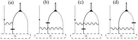
FIG. 3. Diagrams for the radiative recombination of neutral donors D0c0 with free holes hv. The solid (dashed) line rep-resents a free hole (electron); the donor impurity center is represented by a “×” symbol, and the D0
c0 state by “×” in a
dashed circle. Horizontal lines correspond to interlayer tun-neling, wavy lines to Coulomb scattering, and the triangular vertex represents radiative recombination.
IV. ASYMPTOTIC BEHAVIOR FOR LARGE
INTERLAYER TWIST ANGLES
To estimate the quenching of radiative decay as the misalignment angle grows, we evaluate the asymptotic behavior of the radiative rate for large valley mismatch
|∆K|>∼1/a∗0from a perturbative treatment of the short-range interactions (3). In this regime, the rate of ra-diative decay of intralayer complexes is determined by the tail of the momentum-space wavefunction extending toward the opposite layer valley, and which is governed by the large-momentum portion of the interaction term (8a). Thus, we formally split ˆUintra= ˆUintra< + ˆUintra> and
ˆ
Uinter = ˆUinter< + ˆUinter> , where “large” (>) momentum corresponds to wave vectors>∼1/a∗0. Let |Ψ0ibe an ex-citonic state of energyE0
Ψ, of the Hamiltonian ˆ
HLR= ˆH0+ ˆUintra< + ˆUinter< , (16)
containing the long-range approximation to the carrier-carrier and donor-carrier-carrier interaction. The interactions
ˆ
U<
intra and ˆUinter< are given by the expressions (8a) and (8b), respectively, with the substitutions V(0)
(ξ) −→
V<(0)(ξ) and W(ξ) −→ W<(ξ) [see Eqs. (2a) and (2b)].
The state |Ψ0i is perturbed by the interlayer tunneling term ˆHt, as well as the short-range interaction ˆUintra> , ob-tained by substitutingV(0)(ξ)−→ V(0)
> (ξ) in Eq. (8a) [see
Eq. (3)]. As shown in Eq. (3), these terms are inversely proportional to the square of a large wave number, and thus may be treated perturbatively. Furthermore, the short-range interlayer term is exponentially suppressed, and can be ignored altogether. As a consequence, short-range impurity scattering can take place exclusively in the electron layer, where the impurity centers are located (see diagrams of Fig. 3).
In second-order perturbation theory, the correction to the wave function relevant for photon emission is given by
|Ψ(2)0 i=X
m,n
hn|[ ˆHt+ ˆUintra> ]|mihm|[ ˆHt+ ˆUintra> ]|Ψ0i (E0
m−EΨ0)(En0−EΨ0) |
ni,
7 ⇥ ⇥ ⇥ ⇥ ⇥ ⇥ ⇥ ⇥ ⇥ ⇥ ⇥ ⇥ ⇥ ⇥ ⇥ ⇥ ⇥ ⇥ ⇥ ⇥ ⇥ ⇥ ⇥ ⇥
(a) (b) (c) (d)
(e) (f) (g) (h)
⇥ ⇥ ⇥ ⇥ ⇥ ⇥ ⇥ ⇥ ⇥ ⇥ ⇥ ⇥ ⇥ ⇥ ⇥ ⇥ ⇥ ⇥ ⇥ ⇥ ⇥ ⇥ ⇥ ⇥
(a) (b) (c) (d)
(e) (f) (g) (h)
⇥ ⇥ ⇥ ⇥ ⇥ ⇥ ⇥ ⇥ ⇥ ⇥ ⇥ ⇥ ⇥ ⇥ ⇥ ⇥ ⇥ ⇥ ⇥ ⇥ ⇥ ⇥ ⇥ ⇥
(a) (b) (c) (d)
(e) (f) (g) (h)
⇥ ⇥ ⇥ ⇥ ⇥ ⇥ ⇥ ⇥ ⇥ ⇥ ⇥ ⇥ ⇥ ⇥ ⇥ ⇥ ⇥ ⇥ ⇥ ⇥ ⇥ ⇥ ⇥ ⇥
(a) (b) (c) (d)
(e) (f) (g) (h)
[image:7.612.63.290.52.116.2](a) (b) (c) (d)
FIG. 4. Diagrams for the first radiative recombination chan-nel of the D0
c0Xvc0 complex. The bound hole recombines with
the electron from the nearest valley in the opposite layer, as-sisted by short-range Coulomb interactions with the donor impurity. The remaining electron stays bound to the impu-rity center, forming a neutral donor atom.
where the sums run over the eigenstates |ni of ˆHLR, with energiesE0
n. Introducing the light-matter
interac-tion [Eq. (9)], we focus on the diagrams of Fig. 3 for the D0
c0hv complex, and those of Fig. 4 for D0c0Xvc0.
In general, all diagrams must be considered when eval-uating the radiative decay rate. For simplicity, however, we assume that the CB and VB spacings remain the largest scales in the problem, such that~2∆K2
2mα ∆c,∆v.
In this approximation, two out of the four diagrams for D0
c0hv radiative decay cancel out approximately, leaving
only the contributions from the diagrams of Figs. 3(a) and 3(b) (see Appendix C). The resulting radiative de-cay rate for D0
c0hv in the large twist angle (>) limit is
Γ>D0h≈
64π2e4E˜ g
~2r∗02∆K4
e2
~c
h mc0
~2∆K2
i2tccγ
~c∆c −
tvvγ0
~c∆v
2
× |χ0(0)|2|F(r0)|2nh,
(18) where the emitted photon energy is given by E∗ =
˜
Eg−EDb0. Finally,χ0(r) is the D0c0 wave function obtained
from the Keldysh approximation Hamiltonian ˆHLR, not to be confused with the full bilayer interaction bound state χ(r). As before, we evaluate the wave function using the finite-element method, and obtain |χ0(0)|2 = 2.678×10⁻³˚A−2 (Appendix E). We point out that eval-uating the wave functionχ0(r) with the Keldysh poten-tial ignores the formal wave vector cutoff that defines Eq. (16). That is, this solution considers short range in-teractions within the Keldysh approximation, which, as discussed in Sec. II A, overestimate the screening length. Nonetheless, this approximation mainly affects the fast oscillating (large momentum) part of the wave function, whereas Eq. (18), and Eqs. (19) and (20) below, only depend on the smooth, small momentum part. The er-ror incurred by this approximation is proportional to the perturbation squared, and thus beyond our first-order approximation.
With the perturbation ˆU>
intra, there are two possible channels for radiative recombination of the D0c0Xvc0
com-plex, resulting in different final states, and thus two sep-arate lines in the PL spectrum. The first process in-volves one of the electrons and the hole scattering from the donor impurity and subsequently recombining, emit-ting a photon and leaving behind a neutral donor as the final state. This is analogous to the decay process
con-⇥ ⇥ ⇥ ⇥
⇥ ⇥ ⇥ ⇥
(a) (b) (c) (d)
(e) (f) (g) (h)
⇥ ⇥ ⇥ ⇥
⇥ ⇥ ⇥ ⇥
(a) (b) (c) (d)
(e) (f) (g) (h)
⇥ ⇥ ⇥ ⇥
⇥ ⇥ ⇥ ⇥
(a) (b) (c) (d)
(e) (f) (g) (h)
⇥ ⇥ ⇥ ⇥
⇥ ⇥ ⇥ ⇥
(a) (b) (c) (d)
(e) (f) (g) (h)
(a) (b) (c) (d)
FIG. 5. Diagrams for the second radiative recombination channel of the D0c0Xvc0 complex. The bound hole recombines
with the electron from the nearest valley in the opposite layer, assisted by short-range Coulomb interactions with the second electron, at the far valley. The latter recoils and unbinds from the donor impurity.
sidered in Sec. III C, and the corresponding diagrams are shown in Fig. 4. Similarly to the D0
c0hv complex case,
the leading approximation to the amplitude is the sum of two diagrams, giving a radiative rate
Γ>
D0X≈
64π2e4E˜ g
~2r0∗2∆K4
e2
~c
h mc0
~2∆K2
i2 tccγ
~c∆c −
tvvγ0
~c∆v
2 × Z
d2r χ∗0(r)Φ0(0,0,r)
2
|F(r0)|2,
(19) where the emitted photon energy is given by E∗ =
˜
Eg−(EDb0X+EXb), and Φ0(rh,re,re0) is the D0c0Xvc0 wave
function in the Keldysh approximation.
A second radiative decay process is possible, where the recombining electron and hole scatter with the second electron, at the far valley. The latter electron recoils and is unbound from the impurity, taking some amount of kinetic energy and producing a shift in the emission line. The corresponding diagrams are shown in Fig. 5, and give a recombination rate
Γ0>
D0X=
48π2e4E˜ g
~2r0∗2∆K4
e2
~c
h mc0
~2∆K2
i2 tccγ
~c∆c −
tvvγ0
~c∆v
2
× Z
d2r|Φ0(r,r,r)|2.
(20)
The photon energy in this case is given by E∗ = ˜Eg−
Eb
D0 − EDb0X− EXb− ~
2∆K2
2mc0 , and the corresponding line
in the PL spectrum is red shifted with respect to that of the first channel by∼100 meV. Notice the absence of the interference term|F(r0)|2. For this decay channel, the three tunneling processes encoded in Eq. (7) result in different momenta for the recoiling electron, and conse-quently in three distinguishable final states that cannot interfere.
The overlap integrals between the initial- and final-state wave functions given in Eqs. (19) and (20) were evaluated in VMC for the Hamiltonian ˆHLR. We ob-tain
R
d2r χ∗
0(r)Φ0(0,0,r)
2
= 6.94×10⁻⁷ ˚A−4, and
R
d2r
|Φ0(r,r,r)|2 = 3.22×10⁻⁷ ˚A−
4
[image:7.612.326.556.53.120.2]8
Equations (18), (19), and (20) show that the radiative channels considered for the two complexes decay with the interlayer twist angle as θ−8, in the limit ∆K
1/r∗,1/r0
∗. This is shown in Fig. 1(b) for angles larger
than 6◦. Our analysis indicates that, even in the case of localized impurity-bound states, the observation of photoluminescence from interlayer excitonic complexes in TMD bilayers requires near perfect alignment between the two layers.
V. PHONON-ASSISTED RECOMBINATION
Electron-phonon (e-ph) interactions introduce yet an-other channel for radiative recombination. Similarly to the electron recoil process discussed above, when phonons are emitted during the recombination of a given com-plex, they absorb part of the energy and produce a red shifted replica in the PL spectrum. The following anal-ysis is carried out in terms of the VMC wave functions
|Ψidiscussed in Sec. III, evaluated with the exact bilayer interactionsV(0)(ξ) andW(ξ).
The e-ph interaction Hamiltonian is given by
ˆ
He-ph=
X
α=v,c
X
τ,σ X
k,q,ν
gν,α(q)
√
S (b
†
h,ν,−q+bh,ν,q)
×c†α,τ,σ(k+q)cα,τ,σ(k)
+ X
α=v0,c0
X
τ,σ X
k,q,ν
gν,α(q)
√
S (b
†
e,ν,−q+be,ν,q)
×c†α,τ,σ(k+q)cα,τ,σ(k),
(21)
where b†Λ,ν,q (bΛ,ν,q) is the creation (annihilation)
oper-ator for a phonon of momentum q and mode ν in the electron (Λ = e) or hole (Λ = h) layer, which couples to an electron in bandα=c0, v0, c, vwith strengthgν,α(q).
We consider the longitudinal optical (ν = LO), ho-mopolar (ν = HP), and longitudinal acoustic (ν = LA) phonon modes allowed by the lattice symmetry. The e-ph couplings are given by
gLO,α(q) = 1
A s
~
2ρ(Mr/M)ωLO
2πZαe2 1 +qr∗,
gHP,α(q) =
s
~
2ρωHPDα,
gLA,α(q) =
s
~
2ρωLA Ξαq,
(22)
where ρ is the mass density, Mr is the metal-and-two-chalcogen system reduced mass, M is the total mass of the unit cell, andAis the unit-cell area of the correspond-ing TMD layer. ων is the phonon frequency, which we approximate as a constant for the optical modes, and as
ωLA=cLAqfor the LA mode, withcLA being the sound velocity. Z is the Born effective charge,r∗ is the screen-ing length, andDαand Ξαare the deformation potentials
of the optical and acoustic modes, respectively. The vari-ous parameters are taken from Refs. [40–43], and summa-rized in Table III. We focus on the low-temperature limit, where phonon occupation is low and phonon absorption can be neglected.
Perturbative corrections to the interlayer excitonic state|Ψiby the interlayer hopping and e-ph interactions are given by
|Ψ(2)i=X
m,n
hn|[ ˆHt+ ˆHe-ph]|mihm|[ ˆHt+ ˆHe-ph]|Ψi
(Em−EΨ)(En−EΨ) |
ni.
(23) The relevant diagrams for radiative recombination with phonon emission are shown in Figs. 6 and 7 for D0
c0hv
and D0
c0Xvc0, respectively. In both figures, panels (a)–(d)
correspond to single-phonon emission in the hole layer (WSe2), whereas panels (e)–(h) correspond to single-phonon emission in the electron layer (MoSe2). Al-though, in principle, the two sets of diagrams give sep-arate lines at energies determined by the phonon en-ergy in each layer, the parameters reported in Table III show that these lines are within only a few meV of each other. For simplicity, we assume that the two layers have the same optical-phonon energies and the same acoustic-phonon sound velocities, producing a single line in the PL spectrum. The resulting radiative rates are given in the limit of large twist angle (>) by (Appendix D)
Γ>,νD0h≈
48 ˜Eg
~
e2
~c
γ0tvv
~c∆v − γtcc
~c∆c
2
nh
× "
mvgν,v(∆K)
~2∆K2
2
+
mc
0gν,c0(∆K)
~2∆K2
2#
,
(24a)
Γ>,νD0X≈
48 ˜Eg
~
e2
~c
γ0tvv
~c∆v − γtcc
~c∆c
2
×
"
mvgν,v(∆K)
~2∆K2
2
+
mc
0gν,c0(∆K)
~2∆K2
2#
× Z
d2r
Z
d2r0χ∗(r0)Φ(r,r,r0)
2
.
(24b)
The VMC estimate of the overlap ofχ(r0) with Φ(r,r,r0) is 3.85×10⁻⁴˚A−2; see Table VII.
In the small-twist-angle limit (<), phonon emission from D0
c0hv complexes is dominated by the diagram of
Fig. 6(a). In that process, the phonon is emitted by a hole in the WSe2 layer, which then tunnels to recom-bine with the electron bound to the donor impurity. By contrast, all other diagrams shown in Fig. 6 involve ion-ization of the donor atom, which is suppressed by the large binding energy of the D0
c0 complex. The radiative
rates for D0
9
TABLE III. Electron-phonon coupling parameters for LO, HP, and LA phonon modes. ωLOandωHPare the LO- and HP-mode
frequencies,cLAis the speed of sound for the LA mode,ρis the mass density,Dαand Ξαare the deformation potentials of the optical and acoustic modes, respectively,Mr/M is the ratio of the metal-and-two-chalcogen system reduced mass to the total
mass of the unit cell, andZ is the Born effective charge.
~ωLO (meV)~ωHP (meV) cLA(cm/s) ρ(g/cm2) Dc (eV/˚A) Dv (eV/˚A) Ξc (eV) Ξv (eV) Mr/M Z
MoSe2 37 30 4.8×10⁵ 4.5×10⁻⁷ 5.2 4.9 3.4 2.8 0.235 1.8
WSe2 31 31 4.4×10⁵ 6.1×10⁻⁷ 2.3 3.1 3.2 2.1 0.249 1.08
⇥
⇥
⇥ ⇥
⇥ ⇥
⇥
⇥
(a) (b) (c) (d)
[image:9.612.322.562.291.499.2](e) (f) (g) (h)
FIG. 6. Diagrams for the radiative recombination of the D0c0hv complex with phonon scattering. The top four diagrams cor-respond to phonon emission in the WSe2layer and the bottom
four diagrams correspond to phonon emission in the MoSe2
layer.
⇥ ⇥
⇥ ⇥
⇥ ⇥
⇥ ⇥ ⇥
⇥
⇥ ⇥
⇥ ⇥
⇥ ⇥
(a) (b) (c) (d)
(e) (f) (g) (h)
FIG. 7. Diagrams for the radiative recombination of the D0c0Xvc0 complex with phonon scattering and D0c0 in the final
state. The top four diagrams correspond to phonon emission in the WSe2 layer and the bottom four diagrams correspond
to phonon emission in the MoSe2 layer.
D)
Γ<,νD0h=LO/HP≈
2 ˜Eg
π~
e2
~c
γ0tvv
~c∆v
2"
3|gν,c0(∆K)|2
~ων+EDb0
2
+ mv|gν,v(∆K)| 2
|F(r0)|2
~3ων
Z
d2r ei∆K·rχ(r)
2#
nh,
(25a)
Γ<,D0LAh ≈
2 ˜Eg
π~
e2
~c
mvΞ2
v
~2ρc2LA
γ0tvv
~c∆v
2
× Z
d2r ei∆K·rχ(r)
2
|F(r0)|2nh.
(25b)
In the D0
c0Xvc0 case at small twist angles, the phonon
emission process is suppressed by the ionization of the complex in the intermediate state and the overlap inte-gral between the initial D0
c0Xvc0 and final D0c0 states. The
rates are given by
Γ<,νD0X=LO/HP=
4 ˜Eg
~
e2
~c
|F(r0)|2|gν,v(0)|2+ 3|gν,c0(0)|2
(~ων+EDb0X+EXb)2
×
γ0tvv
~c∆v − γtcc
~c∆c
2Z
d2r
Z
d2r0χ∗(r0)Φ(r,r,r0)
2
,
(26a)
Γ<,D0LAX =
˜
Eg
√
2~3cLA
e2
~c
(mv+mc0)3/2 q
Eb
D0X+EXb
γ0tvv
~c∆v − γtcc
~c∆c
2
× "
|F(r0)|2Ξ2v
ρ Z
d2r
Z
d2r0e−i∆K·rχ∗(r0)Φ(r,r,r0)
2
+ 3Ξ 2
c0
ρ0
Z
d2r
Z
d2r0ei∆K·rχ∗(r0)Φ(r,r,r0)
2# ,
(26b) whereρandρ0are the mass densities of WSe2and MoSe2, respectively (Table III).
In Eqs. (24a)–(26b), the electron-layer contributions to the decay rate contain a factor of three originating from the tunneling process, which gives three distinct interme-diate states with different emitted phonon wave vectors, related byC3symmetry. As a result, the interference fac-tor appearing in the interaction-driven processes of Secs. III and IV is absent in this case. For the hole layer, however, the interference factor remains due to the mo-mentum spread of the complex wave function, which lifts the requirement that the hole be scattered exactly onto the electron-layer valley in order to recombine.
Additional contributions to the LO phonon emission come from e-ph interaction of a carrier in one layer with an LO phonon in the other. This is made possible by the long range of the LO phonon-induced potential. The interlayer separation results in an exponential suppres-sion of the potential in the interlayer distance and mo-mentum transfer ase−∆Kd, which nonetheless is
[image:9.612.57.296.404.536.2]10
D0 D0X
0.0 0.5 1.0 1.5 2.0
0.0 0.5 1.0 1.5
ne/nD
n
/
nD
[image:10.612.63.293.51.208.2]nh/nD
FIG. 8. Model for the density of complexes D0c0 and D0c0Xvc0
as a function of the electron densityne.
add this contribution to the LO-phonon-assisted recom-bination rates for D0
c0hv and D0c0Xvc0 complexes in the
small-twist-angle limit.
The total phonon emission rates for the two complexes, combining the three phonon modes, are shown in Fig. 1(b) as functions of the twist angle. As mentioned above, the phonon contribution to the recombination rate is most significant for the D0
c0hvcomplex, being an order of
magnitude larger than for D0
c0Xvc0. The LO phonon mode
in the hole layer (WSe2) is the dominant phonon-assisted process overall, and gives a significant decay rate in the small-twist-angle limit. As a result, we predict additional phonon-replica lines in the PL spectrum, red shifted by the phonon energy~ωLO= 31 meV with respect to the main D0
c0hv and D0c0Xvc0 lines. The D0c0hvphonon-replica
line gives the most dominant feature, with decay rates comparable to the main D0c0hv line.
VI. INTENSITY DEPENDENCE ON DOPING
In addition to the decay rates, the relative line in-tensities also depend on the distribution of D0
c0h and
D0
c0Xvc0 complexes in the system. At charge neutrality,
neutral excitonic complexes such as D0
c0hv are
energeti-cally favorable, whereas additional electrons introduced into the sample will bind to existing neutral donors to form D0
c0Xvc0 complexes. Thus the relative population of
complexes can be controlled through doping.
In this section we model the evolution of the PL spec-trum with the electron carrier density within the range
0 < ne ≤ 2nD, controlled by means of gating18. We
use a simplified zero-temperature model for the occupa-tions of the two complexes, shown in Fig. 8. There are two main regimes determined by the sample-dependent donor density nD. In the p-doped regime, defined by
0< ne< nD, added electrons neutralize the excess
pos-itive donors, forming D0
c0 complexes that can recombine
with the optically pumped holes. In this regime, the for-mation of D0
c0Xvc0complexes is energetically unfavorable,
and thus thermally suppressed until all donors have been neutralized. By contrast, in the n-doped regime, defined
bynD< ne <2nD, it is energetically favorable for
addi-tional electrons to bind with an existing neutral donor to form either a charged donor state D−c0c0 (Table IV), or a
donor-bound trion D0
c0Xvc0. For the latter case we must
consider that laser-pumped holes are scarce (nhnD), and thus the probability of forming a D0
c0Xvc0 complex
will be proportional tonh/nD. The increase in electron density is accompanied by a decrease in D0
c0hv0 numbers,
and a much slower increase in the D0
c0Xvc0 population,
until the number of donor-bound trions in the system equals the number of available holes. This is shown in Fig. 8, and can be summarized as
nD0=
(
ne, ne< nD
nD
h
1−ne−nD
nD
i
, nD< ne<2nD
, (27)
and
nD0X=
(
0, ne< nD
nDnnDhnen−nDD, nD< ne <2nD
. (28)
Eqs. (27) and (28), together with (13), show the de-pendence of nD0 and nD0X on the hole density. This dependence is critical for radiative recombination, given the scarcity of holes by comparison to the donor density. Thus, to give a realistic estimate of the intensity, we con-sider the effects of non-radiative recombination of holes through impurity-driven processes. The density of holes lost through these processes per unit time can be writ-ten asτ0−1nh, whereτ0−1 is the non-radiative decay rate. Assuming that holes are laser-pumped at a constant rate
τ−1
pumpn0, where n0 is a constant with dimensions of in-verse area, the hole density obeys the rate equation
˙
nh=τpump−1 n0−τ0−1nh, (29)
with the steady state solution nh = τ0τpump−1 n0. In the p-doped regime, delocalized holes can recombine non-radiatively with the electrons present in the sample, and the non-radiative lifetime can be assumed of the form
τ0=c0/ne, with c0 a constant. Thus, writing the D0c0hv
radiative intensity asID0h= ΓD0hnD0, we obtain the ex-pression
ID0h=
4 ˜Eg|F(r0)|2
~
e2
~c
tvvγ0
~c∆v −
tccγ
~c(∆c+EDb0)
2
× Z
d2r ei∆K·rχ(r)
2
c1,
(30)
where c1 =c0n0τpump−1 is a constant independent of the electron density.
A similar argument can be made for the n-doped regime. In this case, the intensity is given by ID0X = ΓD0XnD0X, where the number of donor-bound trions can be approximated asnD0X=nh(ne−nD)/nD. However, in this regime the holes will be localized near the donor-impurity sites forming D0
c0Xvc0 states, where they will be
[image:10.612.320.562.203.293.2]11
0.0 0.2 0.4 0.6 0.8 1.0
0.0 0.2 0.4 0.6 0.8
0.0 0.1 0.2 0.3 0.4 0.5 0.6
0.0 0.1 0.2 0.3 0.4
1.15 1.20 1.25 1.30 1.35 1.40 1.45 1.50 0.00
0.05 0.10 0.15 0.20
ne= 1.8nD
ne= 1.6nD
ne= 1.4nD
ne= 1.2nD
D0h D0X D0h+ ph D0X+ ph
total
I
[a
.
u
.
]
E[eV]
nenD
<latexit sha1_base64="623fgvL47rYKL/dwqxVn8dmoHUQ=">AAAB8nicbVBNS8NAEJ3Ur1q/qh69LBbBU0lE0GNRDx4r2A9oQ9hsJ+3SzSbsboQS+jO8eFDEq7/Gm//GbZuDtj4YeLw3w8y8MBVcG9f9dkpr6xubW+Xtys7u3v5B9fCorZNMMWyxRCSqG1KNgktsGW4EdlOFNA4FdsLx7czvPKHSPJGPZpKiH9Oh5BFn1FipJwMkfYFEBndBtebW3TnIKvEKUoMCzaD61R8kLItRGiao1j3PTY2fU2U4Ezit9DONKWVjOsSepZLGqP18fvKUnFllQKJE2ZKGzNXfEzmNtZ7Eoe2MqRnpZW8m/uf1MhNd+zmXaWZQssWiKBPEJGT2PxlwhcyIiSWUKW5vJWxEFWXGplSxIXjLL6+S9kXdc+vew2WtcVPEUYYTOIVz8OAKGnAPTWgBgwSe4RXeHOO8OO/Ox6K15BQzx/AHzucPS+KQmA==</latexit><latexit sha1_base64="623fgvL47rYKL/dwqxVn8dmoHUQ=">AAAB8nicbVBNS8NAEJ3Ur1q/qh69LBbBU0lE0GNRDx4r2A9oQ9hsJ+3SzSbsboQS+jO8eFDEq7/Gm//GbZuDtj4YeLw3w8y8MBVcG9f9dkpr6xubW+Xtys7u3v5B9fCorZNMMWyxRCSqG1KNgktsGW4EdlOFNA4FdsLx7czvPKHSPJGPZpKiH9Oh5BFn1FipJwMkfYFEBndBtebW3TnIKvEKUoMCzaD61R8kLItRGiao1j3PTY2fU2U4Ezit9DONKWVjOsSepZLGqP18fvKUnFllQKJE2ZKGzNXfEzmNtZ7Eoe2MqRnpZW8m/uf1MhNd+zmXaWZQssWiKBPEJGT2PxlwhcyIiSWUKW5vJWxEFWXGplSxIXjLL6+S9kXdc+vew2WtcVPEUYYTOIVz8OAKGnAPTWgBgwSe4RXeHOO8OO/Ox6K15BQzx/AHzucPS+KQmA==</latexit>
<latexit sha1_base64="623fgvL47rYKL/dwqxVn8dmoHUQ=">AAAB8nicbVBNS8NAEJ3Ur1q/qh69LBbBU0lE0GNRDx4r2A9oQ9hsJ+3SzSbsboQS+jO8eFDEq7/Gm//GbZuDtj4YeLw3w8y8MBVcG9f9dkpr6xubW+Xtys7u3v5B9fCorZNMMWyxRCSqG1KNgktsGW4EdlOFNA4FdsLx7czvPKHSPJGPZpKiH9Oh5BFn1FipJwMkfYFEBndBtebW3TnIKvEKUoMCzaD61R8kLItRGiao1j3PTY2fU2U4Ezit9DONKWVjOsSepZLGqP18fvKUnFllQKJE2ZKGzNXfEzmNtZ7Eoe2MqRnpZW8m/uf1MhNd+zmXaWZQssWiKBPEJGT2PxlwhcyIiSWUKW5vJWxEFWXGplSxIXjLL6+S9kXdc+vew2WtcVPEUYYTOIVz8OAKGnAPTWgBgwSe4RXeHOO8OO/Ox6K15BQzx/AHzucPS+KQmA==</latexit>
[image:11.612.60.297.52.360.2]<latexit sha1_base64="623fgvL47rYKL/dwqxVn8dmoHUQ=">AAAB8nicbVBNS8NAEJ3Ur1q/qh69LBbBU0lE0GNRDx4r2A9oQ9hsJ+3SzSbsboQS+jO8eFDEq7/Gm//GbZuDtj4YeLw3w8y8MBVcG9f9dkpr6xubW+Xtys7u3v5B9fCorZNMMWyxRCSqG1KNgktsGW4EdlOFNA4FdsLx7czvPKHSPJGPZpKiH9Oh5BFn1FipJwMkfYFEBndBtebW3TnIKvEKUoMCzaD61R8kLItRGiao1j3PTY2fU2U4Ezit9DONKWVjOsSepZLGqP18fvKUnFllQKJE2ZKGzNXfEzmNtZ7Eoe2MqRnpZW8m/uf1MhNd+zmXaWZQssWiKBPEJGT2PxlwhcyIiSWUKW5vJWxEFWXGplSxIXjLL6+S9kXdc+vew2WtcVPEUYYTOIVz8OAKGnAPTWgBgwSe4RXeHOO8OO/Ox6K15BQzx/AHzucPS+KQmA==</latexit>
FIG. 9. Simulated normalized PL spectra for a closely aligned (θ ≈ 0◦) MoSe2/WSe2 heterobilayer, originating from the
D0
c0hv and D0c0Xvc0 complexes at different electron densities
ne, given in terms of the fixed donor density nD. Dashed
curves correspond to the phonon replicas. The lines are as-sumed to have Gaussian shapes of width 2σ= 60 meV, and we usenh= 1011cm−2 andnD= 1013cm−2.
the non-radiative decay rate asτ0=c0/2nD. This leads to
ID0X=
(ne−nD) 2n2
D
c1ΓD0X. (31)
The resulting simulated PL spectrum is shown in Fig. 9 for different doping densities, given in terms of the donor density in the MoSe2layer. A Gaussian line-shape was used for the lines with an experimentally motivated broadening18 of 2σ= 60 meV. The spectrum shows the three dominant lines, D0
c0hv, D0c0Xvc0, and the red-shifted
phonon replica of D0
c0hv, with the lines’ peak energies
determined by the DMC-obtained binding energies. The three complexes evolve with doping as prescribed by Eqs. (30) and (31). The D0
c0hv complex and its phonon replica
dominate for 0< ne < nD; then, the D0c0Xvc0 line grows
slowly in intensity in the n-doped regime, with a simul-taneous reduction in the intensity of the D0
c0hv complex.
For the broadening used in the simulated PL spectrum, the proximity of the three lines results in an intricate line form, providing a signature in PL experiments for
the intrinsic structure of the interlayer emission line.
VII. CONCLUSIONS
The momentum mismatch between twisted and incom-mensurate heterobilayer TMDs prevents efficient radia-tive recombination of interlayer complexes composed of electrons and holes localized on opposite layers. In this paper we described mechanisms that bridge the momen-tum gap involving donor impurities present in the hetero-bilayer system, both at small and large twist angles. The donor impurities were found to provide deep potential wells (∼200 meV), resulting in strongly bound interlayer complexes, as revealed by DMC calculations. Focusing on the simplest multiparticle complexes, we estimate ra-diative rates of up to a fewµs−1 for the neutral donor with a free hole D0
c0hvand the donor-bound trion D0c0Xvc0
complexes for closely aligned layers, and a strong twist-angle suppression for large misalignment with the asymp-totic form∝θ−8. A comparable contribution was found for the D0
c0hv complex from emission of optical phonons,
resulting in a total of three dominant and doping-tunable lines in the PL spectrum. The D0
c0hvline and its phonon
replica are expected to dominate the emission spectrum for electron densities below the sample-dependent donor concentration; conversely, PL from the D0
c0Xvc0 complex
is expected to dominate the interlayer sector of the spec-trum when the electron density exceeds the density of donors.
Based on QMC simulations, we have shown that our qualitative results are robust against uncertainty in model parameters, such as the band effective masses, as well as sample-dependent dielectric properties. There-fore, our predictions provide a new perspective for inter-preting recent experimental observations of interlayer lu-minescence in heterobilayers of transition-metal dichalco-genides.
All relevant data present in this publication can be accessed at Lancaster University44.
ACKNOWLEDGMENTS