Burroughs
VISIBLE RECORD
-COMPUTER SYSTEM
Reference Manual
•
•
•
•
B251
•
•
•
•
•
•
•
•
•
•
•
•
•
•
•
•
•
•
•
•
•
•
•
•
•
•
•
•
•
•
•
•
•
•
•
THE BURROUGHS B251
BULLETIN 251-21 00l-P
DECEMBER 20, 1960
VISIBLE RECORD COMPUTER SYSTEM
REFERENCE MANUAL
Sales Technical Services
Equipment and Systems Marketing Division
Burroughs Corporation
TABLE OF CONTENTS
SECTION 1 - INTRODUCTION .
B
251
Visible Record Computer System Data Processing SystemsData Processor . Program Card Reader Sorter-Reader
Record Processor Console and Keyboard
SECTION 2 - STORAGE AND INPUT-OUTPUT MEDIA Internal Storage.
Punched Card MICR Documents Visible Record
SECTION 3 - PROCESSING FUNCTIONS Logic .
Arithmetic Masking . Input Control Output Control Internal Checking Programmed Checking
SECTION 4 - PROGRAMMING Instruction Format
Operation Code Variants . Addressing Instructions No Operation Add. Subtract Multiply Divide Compare-Branch Equal Branch .
Transfer. Mask Halt. Card Read
Sorter Read, Demand Sorter Read, Flow. Control Sorter . Record Processor Read
Record Processor Write and Eject Record Processor Print
TABLE OF CONTENTS (Continued)
SECTION 5 - SYSTEM COMPONENTS. B 101 Sorter-Reader.
Sorter-Reader Control Panel Data Processor .
Data Processor Console Program Card Reader .
Program Card Reader Functional Operations Program Card Reader Display Panel . The Record Processor .
Record Processor Functional Operation Console and Desk
Console Control Panel Console Keyboard .
SECTION 6 - ASSEMBLER FOR THE B 251 VISIBLE RECORD COMPUTER SYSTEM
Introduction .
Assembler Programming Procedures Assembler Coding Form
Control Entries .
Special Addressing Techniques Pseudo Op Codes
Assembly Operations
B 251 Assembler Instruction List.
APPENDIXES
ApPENDIX A
Word Formatting of MICR Information in Storage
ApPENDIX B
B 251 Command List
ApPENDIX C
VRC Code Reference Table (Collating Sequence)
ApPENDIX D
Flow Chart Standard Symbols. Input-Output
Logic
ApPENDIX E
Timing Chart
Internal Operations Input-Output Operations
Page
5.:1
5-1 5-1 5-2 5-2
5-4
5-4
5-4
5-5 5-6 5-9 5-9 5-12
6-1
6-1
6-1
6-1
6-4 6-4 6-7 6-7 6-8
A-1
B-1
C-1
D-1 D-1 D-1
LIST OF ILLUSTRATIONS
Figure Page
1-1 Functions of a Computer System 1-1
1-2 The Five Functions of the VRC System 1-1
1-3 The Data Processor 1-2
1-4 The Program Card Reader 1-2
1-5 The Sorter-Reader 1-3
1-6 The Record Processor 1-3
1-7 The Console and Keyboard 1-4
2-1 Seven-Core Storage Location 2-1
2-2 Binary-Coded Character Representations 2-1
2-3 Punched Card Codes . 2-2
2-4 E 13B Type Font Characters 2-2
2-5 Standard Paper Check Format 2-3
2-6 Encoded Check With Transit Number. 2-3
2-7 Amount Field . 2-4
2-8 Pre-Encoded On-Us Field 2-4
2-9 Post-Encoded On-Us Field 2-4
2-10 Transit Field 2-5
2-11 Auxiliary On-Us Field 2-5
2-12 Addressing with Bar Code 2-5
2-13 Account Record (With Magnetic Stripe and Bar Code) 2-6
3-1 Basic Demand Deposit Accounting . 3-1
5-1 Sorter-Reader I tern Processing Route 5-1
5-2 Sorter-Reader Control Panel 5-2
5-3 Data Processor Console 5-3
5-4 Program Card Reader 5-4
5-5 Program Card Reader Display Panel 5-5
5-6 The Record Processor 5-6
5-7 Record Processor Schematic . 5-7
5-8 Examples of Different Form Sizes 5-8
5-9 Console and Desk . 5-9
5-10 Console Control Panel 5-10
5-11 Power and Magazine Switches 5-11
5-12 Console Keyboard 5-11
SECTION 1
INTRODUCTION
B 251 VISIBLE RECORD COMPUTER SYSTEM
The B 251 VRC is a completely transistorized, stored - program computer system consisting of the B 250 Data Processor, the B 401 Record Processor and Keyboard Console" the BIOI Sorter-Reader, and the B 122 Program Card Reader. This system is designed to handle, as input media, MICR (Mag-netic Ink Character Recognition) encoded docu-ments, punched cards, magnetically encoded ac-count records, and keyboard entries.Jor supervisory control. As output media, the B 251 VRC System is unique in that it automatically produces a printed hard copy account record with updated, magnetic-ally encoded account information and printed jour-nals for management statistics and reports.
This system provides for the first time a means of combining electronic data processing with MICR and producing hard copy accounting records at high speeds. Another first with the B 251 VRC System is the addition of a magnetic stripe on the back of the account records for storing pertinent identification and account information. This provides a means of communication between the hard copy account rec-ord and the automatic equipment. Thus one me-dium provides storage for automatic processing and visual reference.
This manual is intended to introduce and define the B 251 VRC System to those who desire specific in-formation about it, and to describe in easily under-standable terms the complete system and its opera-tion for those who will use i~. Prior to reading this manual it would be to the reader's advantage to be familiar with the Burroughs BIOI Sorter-Reader Operator's Manual and the American Bankers Asso-ciation specifications for the Common Machine Lan-guage (Bank Management Publication 147).
DATA PROCESSING SYSTEMS
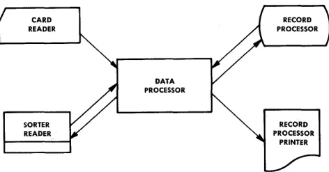
[image:8.613.360.546.202.328.2]Data processing systems require five basic func-tions: input, storage, arithmetic, output, and control (Figure 1-1).
INPUT OUTPUT
Figure 1-1. Functions of a Computer System
The input function transmits data to the system by means of several input devices, depending on the desired "input media.
The storage section holds the data received from the input units and keeps it available for operations by other parts of the system.
The arithmetic function handles the actual process-ing, or manipulation, of data. It is the computing function of the system which accomplishes all prob-lem solving.
The output function transmits processed results from storage to the output devices and converts them to a usable form.
The control function directs the flow of data from input to storage, storage to arithmetic, arithmetic to storage, and from arithmetic or storage to output.
CARD READER
SORTER READER
DATA PROCESSOR
RECORD PROCESSOR
[image:8.613.337.573.582.706.2]Figure 1-2 illustrates the manner in which these five functions comprise the Burroughs B 251 Visible Record Computer System.
The following are brief descriptions of the component units of the B 251 VRC System, including an expla-nation of how each performs one or more of the five basic functions of data processing systems.
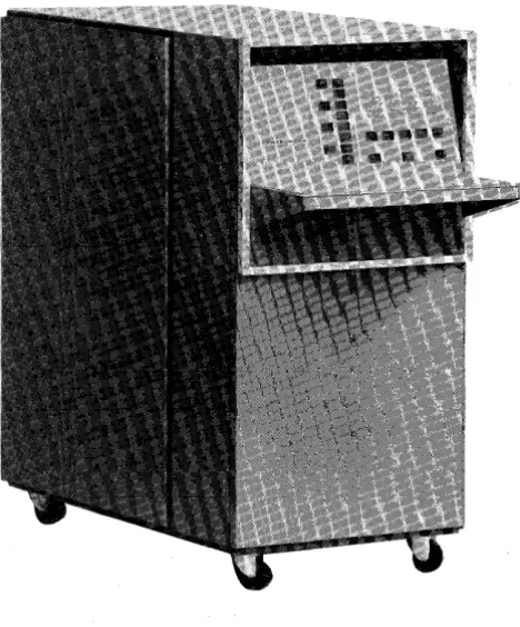
DA T A PROCESSOR
The Data Processor (Figure 1-3) is the nerve center of the B 251 VRC System. Within its transistorized circuitry are logic, checking, and decision-making abilities and the ability to perform the four basic arithmetic functions. This single unit controls all input, output, and formatting. It contains 4800 char-acters of alphanumeric magnetic core storage. On the front of the Data Processor is a display panel indicating its operating condition at all times and providing control for manual operation.
Figure 1-3. The Data Processor
The Data Processor also provides for buffering of the information from the card reader and the Sorter-Reader. That is, information read from a card or an item is held in the Data Processor buffer until it is called for by the required read instruction.
PROGRAM CARD READER
The Program Card Reader (Figure 1-4) is an input device for the B 251 VRC System. It is used prima-rily for loading programs (the instructions telling the system what operations to perform and in what order) from punched cards. It can also be used for entering exceptions or other extra data into the system. The card reader operates at a speed of 100 cards per minute. The card reader also has a display panel for indicating its operating condition.
Figure 1-4. The Program Card Reader
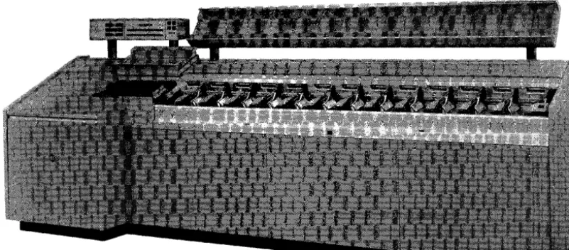
SORTER-READER
[image:9.615.317.521.220.510.2] [image:9.615.43.277.345.627.2]Figure 1-5. The Sorter-Reader
[image:10.626.109.510.134.310.2] [image:10.626.137.505.376.708.2]pocket. Above and to the rear of the pockets is a mobile carrier, for ease of handling the documents, and a temporary storage area. The control panel provides indicators and operating buttons for effi-cient operation of the Sorter-Reader. Field and digit position selection buttons are provided for off-line operation.
RECORD PROCESSOR
The Record Processor (Figure 1-6) automatically processes account records. Records are fed from a magazine in the primary feed station, from the auxiliary feed station, or from the manual feed sta-tion. The Record Processor will read account infor-mation from the magnetic stripe on the back of the visible record and store it in the core memory of the Data Processor. This unit contains a 160-position printer, which prints on the face of the record and two separately controlled continuous journals simul-taneously or individually. Updated account informa-tion can be written from core memory to the magnetic stripe and the record ejected to a magazine in the primary stacker station or segregated to the auxiliary stacker station.
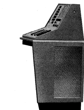
CONSOLE AND KEYBOARD
The Console and Keyboard (Figure 1-7) provide the communication between the B 251 VRC System and
Figure 1-7. The Console and Keyboard
[image:11.615.326.489.57.270.2]SECTION 2
STORAGE AND
INPUT-OUTPUT MEDIA
INTERNAL STORAGE
The B 251 Visible Record Computer System utilizes magnetic cores for internal storage or memory, each core storing one bit of information. A bit is one-seventh of a binary-coded alphanumeric character. The binary number system which is built on only two numbers, zero and one,_ is employed by the B 251 System for representing information within the computer. This is done because of the simplicity of representing the two numbers by any two-state device. The magnetic core is an example of a two-state device. It is used to represent a one (is on) when it is magnetized in one direction, and repre-sents a zero (is off) when it is magnetized in the other direction.
It takes seven binary bits to make up one binary-coded alphanumeric character; thus it takes seven magnetic cores to form one storage location (Figure 2-1). The first four bits are assigned the values 8, 4, 2, 1, respectively, each bit representing that value only when the core is in the one or on state. These first four bits can store any binary-coded decimal digit.
The next two bits are called the zone bits. These bits in combination with the first four can store any binary-coded alphabetic or special character nor-mally used. The seventh bit (parity bit) provides for
Figure 2-1. Seven-Core Storage Location
internal checking on the bit configuration, being on or off as necessary to make the number of on bits in any configuration always odd. Figure 2-2 shows the binary-coded character representation employed by the B 251 System.
Each character position in magnetic core storage is individually addressable. That is, each storage
[image:12.612.408.476.220.441.2] [image:12.612.74.542.573.702.2]0123456789
10
11
21
31
41
51
61
71
81
91
o
1 2 3 4 5 6 7 8 9o
1 2 3 4 5 6 7 8 9o
1 2 3 4 5 6 7 9 9 ABCDEFGHIJKLMNOPQRSTUVWXYZ111111111
111111111
o
0
011111111
11
11
1
12
21
21
13
31
31
14
41
41
15
51
51
16
61
61
17
71
71
18
81
81
[image:13.613.109.492.68.244.2]19
91
91
Figure 2-3. Punched Card Codes
tion has an individual label or address by which it might be referenced in order to obtain the informa-tion stored there for computainforma-tion.
A program instruction will designate the precise ad-dress of the location storing the information needed for a particular program step.
PUNCHED CARDS
Punched cards can be considered a form of external storage for the VRC System in addition to their primary use as input media. Once a program or set of data has been punched into a deck of cards, that deck can be set aside and used over and over for the same computer application. Alphanumeric charac-ters can be punched into a card for direct entry to computer storage through the Program Card Reader.
The punched card is divided into 80 vertical col-umns. A total of 80 characters may be punched in one card, each character occupying one of the 80 columns.
Punching takes place in two areas on a card; the lower (numeric) section and the upper (zone) sec-tion. The' numeric section is divided into 10hori-zontal rows, one row for each digit 0 to 9. The zone section is divided into three horizontal rows, 0, 11, and 12. The 0 row is common to both the zone and numeric sections.
See Figure 2-3 for a schematic of card character coding.
Holes punched in their proper rows and specified columns are automatically identified as characters by the B 251 System. Digits are represented by single punches in the numeric section, letters and special characters by combinations of zone and digit punches. The combination of the twelve zone and one of the -digits 1 through 9 is recognized by the B 251 System as one of the letters A through I, the eleven zone
with a digit 1 through 9 as J through R and the zero zone with a digit 2 through 9 as S through Z. Special characters are represented by various combinations of zone and digit punches.
MICR DOCUMENTS
The B 251 System utilizes the Burroughs B 101 Sorter-Reader as an input device for reading MICR encoded documents. MICR, upon which the Sorter-Reader is based, represents Magnetic Ink Character Recognition. The Sorter-Reader is designed to read 14 magnetic characters which conform to standards of size, shape, and quality set by the Office Equip-ment Manufacturers' Committee and the American Bankers Association. These characters consist of the 10 digits 0 through 9 and four special symbols: amount symbol, dash symbol, transit or routing symbol, and the on-us symbol. The 14 characters, printed in type font E 13B, are illustrated in Figure 2-4.
O~2~L.
ZERO ONE TWO THREE FOUR
51;r8'1
RYE SIX SEVEN EIGHT NINE
III
AMOUNT SYMBOl. .... -...
_
....--
... _._ ... .IlioN
US SYMBOL... _.-...
-._
... _ ... _ ... -... __ ... .I -
TRANSIT NUMBER SYMBOL--_._-....
_ ..._---
... _ .... _ ... .III
DASH SYMBOL [image:13.613.317.541.499.710.2]BURROUGHS CORPORATION
THE TODD COMPANY DIVISION
LOCATION OF MAGNETIC CODE PRINTING
TRANSIT NUMBER ACCOUNT NUMBER AND AMOUNT FIELD ROUTING SYMBOL
I
FIELDI
TRANSACTION CODE FIE.LDI
I
i
i
i
i
143 42 41 4039383736353433132 31 30292827 262524 23 22 21 20 19 18 17 16 15 14 13112 11 10 9 8 7 6 5 4 3 2 11
I I
I I I I
I
~NO MAGNETIC PRINTING OTHER THAN CODING BELOW THIS LINE
I I I
I
I I I I
I
I I
I
I
I I
I I I I
I I I
I
I
I I
I I
I
I
I I I
I
I
I I
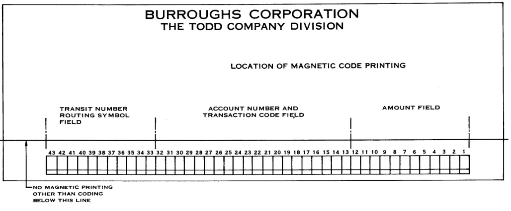
Figure 2-5. Standard Paper Check Format
Figure 2-5 illustrates a standard paper document format used as input media to the B 251 System.
In the following field descriptions it will become obvious that certain encoding positions are ignored. This is due to tolerance requirements between pre-encoded and post-pre-encoded information. For example, a book of checks purchased by a depositor would have the transit and account numbers encoded on each check (Figure 2-6), whereas a counter check would have only the transit number encoded; the account number would have to be encoded after the check had cleared, prior to processing.
PROGRESSIVE BANK
BURROUGHSVILLE
PAY TO THE
Additional information on field location specifica-tions may be obtained from the BIOI Sorter-Reader Manual, Chapter IV, Section 2 and the American Bankers Association Specifications on the Common Machine Language (Bank Management Publication 147).
In the lower right portion of a document is the amount field (Figure 2-7) which occupies positions 1 through 12. Twelve characters must always be present regardless of the amount. Leading zeros are never eliminated. The amount field consists of 10 digits, bracketed by amount symbols.
_________________________________________ 19 __ __ oo-e678
1234
ORDER OF---________________________ S __________ __
SPECIMEN NOT VALID
[image:14.612.61.575.77.290.2] [image:14.612.63.568.491.697.2]AMOUNT FIELD
I i
1S 14 13 12 11 10 9 8 7 6 S 4 3 2 1 :
-1
J~I~~loJoloJQI~~~I~ kl~
I i
Figure 2-7. Amount Field
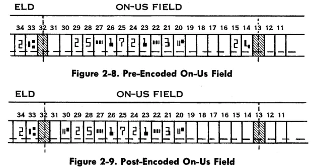
[image:15.612.69.254.70.151.2]The account number or on-us field occupies positions 13 through 32 and includes the transaction code (Figure 2-8). The length of the account number and transaction code may vary but the total number of characters cannot exceed 20, of which only 19 are normally usable due to tolerance requirements. The on-us symbol (position 20 in this example) to the left of the transaction code (positions 14 and 15) is used to define or end the transaction code field. The account or on-us field (positions 21-29) appears to the left of the on-us symbol. The symbol that ends the on-us field and the position it occupies will vary, depending on the length of the account num-ber and when it is encoded. When the on-us and transit fields are encoded at the same time, the tran-sit symbol (potran-sition 33) ends the on-us field.
When the two fields are encoded at different times the on-us symbol may also be encoded to the left of the on-us field and to the right of the transit symbol (Figure 2-9) .
The transit field (Figure 2-10) occupies positions 33 through 43. Within these 11 positions will be two transit symbols, one each in positions 33 and 43, a dash in position 38, and the eight digits of the transit number in the other positions.
Note .that in both the on-us and transit fields, the dash symbol may be used to separate digits to facili-tate visual reading.
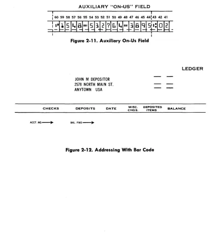
A fourth field, the auxiliary on-us or account number field (Figure 2-11), is also available on items which
exceed 6~4 inches in length. The auxiliary on-us field is located immediately to the left of the transit field and may contain as many characters, not to exceed 16, as can be bracketed between the transit symbol in position 43 and the on-us symbol which is the ending symbol for the field.
The method of storing magnetically encoded docu-ment data in core memory is covered in Appendix A.
VISIBLE RECORD
The visible account record (Figure 2-13) is an im-portant form of input-output media employed by the B 251 System. In addition to its primary use as input-output media, it might be considered as ex-ternal storage for the system in that it stores in-formation in a magnetic stripe which can be read into storage for processing at any time, and it stores visible printed information which can be referred to at any time.
The magnetic stripe (Figure 2-13) is located on the back of the account record. It runs vertically from top to bottom of the record, is approximately .2 inch wide and the center is 2.1 inches from the left edge.
Eighty-one digits of six bits each can be written on the stripe, the bits being packed 60 to the inch. The six bits comprising a digit are the binary 8, 4, 2, and 1 bits, one zone bit and the odd parity bit. The zone bit is used to represent a negative number; absence of the zone bit indicates a positive number. The combination of one, two, three, or four of the 8, 4, 2, 1 bits represents a number 0 through 15. Odd parity, as previously explained, is the assurance that all digits will have an odd number of bits including the parity bit.
Primarily the magnetic stripe is used for storing information pertinent to a specific account.
How-ELD ON-US FIELD
.
31 30 29 28 27 26 2S 24 23 22 21 20 19 18 17 16 1S 14 1~ 12 11
~---.--Figure 2-8. Pre-Encoded On-Us Field
ELD ON-US FIELD
[image:15.612.139.450.559.726.2]TRANSIT NUMBER FIELD
I
[image:16.615.90.288.63.144.2]'43 42 41 40 39 38 37 36 35 34 33 I
Figure 2-10. Transit Field
ever, it can also be used for other purposes, such as storage of data pertaining to controls, statistics, re-ports, constants, etc. Information from the magnetic stripe can be read into the Data Processor for processing at any time; and new, updated or par-tially updated information can be written back on the stripe from storage.
In addition to the magnetic stripe on the back of the visible account record, the record itself is a most important form of output media. All account trans-actions and balances are printed from Data Proc-essor storage on the face of the record. This is the hard copy produced at high speed which is provided by the B 251 System.
As an optional feature the account record may have a bar code as shown in Figure 2-12. This code is normally the last two characters of the account number. It is used for matching account numbers in core storage with those preprinted on the face of the account record.
AUXILIARY "ON-US" FIELD
: I
I 60 59 58 57 56 55 54 53 52 51 50 49 48 47 46 45 44143 42 41
~~.~~ 1~~I~~lD ~~~IIPI81~
5~:l$W-IFigure 2-11. Auxiliary On-Us Field
JOHN M DEPOSITOR 2578 NORTH MAIN ST. ANYTOWN USA
LEDGER
CHECKS DEPOSITS DATE CHGS. MISC. DEPOSITED ITEMS BALANCE
ACCT. NO.---+- BAL.
[image:16.615.103.518.247.711.2]"TI
ca·
e...
CD
~
I
-~
»
n n0
e
::I
-;Ia CD
n
0
..
iii.) D.
I
i
~
=
:7 ~Q CQ
::I
!.
ft·
~
..
-s.
CDQ
::I D.
." Q
..
n
0 D.
.!..
CHECKS
ACCT.NO.~
JOHN M DEPOSITOR 2578 NORTH MAIN ST. ANYTOWN USA
DEPOSITS DATE
BAL.FWD.~
MISC. DEPOSITED CHGS. ITEMS
LEDGER THE PROGRESSIVE BANK
BURROUGHSVILLE
BALANCE CHECKS DEPOSITS DATE NO. BALANCE
BALANCE BROUGHT FORWARD ~
CODE
EC • ERROR CORRECTION 00 • OVERDRAWN
CM • CREDIT MEMO RT • RETURNED CHECK
LS • LIST OF CHECKS SC • SERVICE CHARGE
CC • CERTIFIED CHECK OM • DEBIT MEMO Burroughs Corporation
g )
-D'E M 0 N S T RAT IN G FOR M
SERVICE CHARGE
NO. OF
I
DATE CHECKS PAID
I
SECTION 3
PROCESSING FUNCTIONS
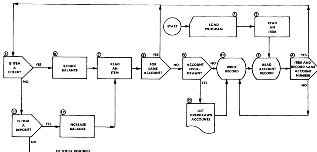
Data processing is the performance of a series of actions or operations on data for the purpose of achieving a desired result. The Burroughs B 251 Visible Record Computer System employs the most advanced electronic techniques to perform these functions with the greatest efficiency. In order to control the operations of data processing within the computer system, a series of instructions or mands, called a program, is introduced to the com-puter to tell it under what circumstances to perform what operations on the data being processed. These instructions will tell the computer to perform opera-tions-such as read, write, print, add, subtract, multiply, divide, transfer, compare, and branch-that are necessary to process the data in the manner desired. Figure 3-1 is a flow diagram of a basic de-mand deposit accounting program for a bank. A flow diagram or flow chart is a logical statement of the operations and decisions involved in anyone
IS ITEM YES A
CHECK?
NO
YES
REDUCE BALANCE
INCREASE BALANCE
TO OTHER ROUTINES
READ AN ITEM
problem to be solved. Preparation of a flow diagram is the first step in the process of preparing a working program. The analyst who conceives the idea of a computer application sets his plan down on paper in the form of a flow diagram. The flow diagram is then used as a guide in preparing the list of instructions which will tell the computer how to solve the prob-lem. This programming, or coding, is much simpler when a good flow diagram is available: the program-mer need only formulate the instructions necessary to accomplish the job set forth in each box of the diagram in the order that the boxes appear. (Figure 3-1). There are several flow diagram symbols which have become standard. (Appendix D).
In the paragraphs that follow, the processing func-tions of the B 251 VRC System will be discussed. They will be explained in greater detail in later sec-tions of this manual that deal directly with the instructions.
2
YES
[image:18.618.60.574.452.698.2]NO
LOGIC
Primarily, the function of the logic of a data proc-essing system is to execute program instructions in order. In addition, its purpose is to evaluate and weigh conditions and, if necessary, select alternate routines. Figure 3-1 illustrates typical logical de-cisions which must be made. For example, step 5 asks, "Is this item a check?" If the answer is yes, the logical sequence continues and the item is processed as a check. If the answer is no, program control will branch to step 11 to determine if the item is a deposit.
The B 251 VRC System's logic is designed to test, prove, and compare, in order to decide if program control should branch or continue in sequence to perform all of the program steps necessary to com-' plete a routine.
ARITHMETIC
The B 251 System has the ability to add, subtract, multiply, and divide. All arithmetic functions are standard equipment; no subroutines are required for multiply or divide. To illustrate two of the arithmetic functions of the system, refer to Figure 3-1, steps 6 and 12. To reduce the account balance, the item amount is subtracted from the balance. To increase the balance, the item amount is added to the balance. The arithmetic and logic units do not store information, -but merely operate on the char-. acters as they pass through the computerchar-. Their
functions are to receive data from storage, operate on it in accordance with instructions received, and deliver it either back to storage or to an output media.
MASKING
The complete editing (masking) of all output data is under program control. Step 13 of Figure 3-1 includes the masking of the account number and overdrawn balance to insert the desired punctuation and symbols and deliver the masked data to the printer output area in storage for printing. A more detailed explanation of masking will be found in Section 4 of this manual.
INPUT CONTROL
As previously mentioned, the B 251 Visible Record Computer System has great flexibility in that it uti-lizes the Program Card Reader, Sorter-Reader, Record Processor, and Console Keyboard for a wide variety of inputs. Figure 3-1 illustrates three of these input devices. Step 1 shows how the Program Card Reader is used to load the program into core storage. It can
also be used to read exceptions, daily constants, or other data for an individual application. The use of the Sorter-Reader as input to read MICR encoded documents, such as bank items, accounts receivable, inventory control, etc., is illustrated in steps 2 and 7. In step 3 the Record Processor is used to read account information from the magnetic stripe on the back of the account record. Although it is not used in this example, the Console Keyboard is a valuable input device for manually entering input data.
OUTPUT CONTROL
The B 251 VRC System makes possible a new con-cept in output media, a hard copy visible record .. The B 251 System will render a complete record for normal distribution without the rewriting and edit-ing on auxiliary equipment necessary with other computers. Refer once again to Figure 3-1 for illus-trations of output from the Visible Record Com-puter. Step 10 shows where the updated account information is recorded on the magnetic stripe on the back of the account record. Listing reports and statistics on the continuous journals can be accom-plished, as shown in step 13. Although not shown on the flow diagram, the Sorter-Reader is also a form of output control via pocket select.
INTERNAL CHECKING
Parity checks are standard features of the B 251 System. Parity checking is usually construed to mean a form of redundancy checking, based on an odd or even number of binary ones which form a character. For example, in the B 251 System binary representation of a character, a parity bit is made either zero or one, whichever is required to make the number of ones in the character an odd number. Refer to Figure 2-2, which shows the bit representa-tion of a character.
PROGRAMMED CHECKING
SECTION 4
PROGRAMMING
The processing functions of the B 251 System are initiated by program instructions. There are instruc-tions for input and output control, for performing logical operations and arithmetic, and for general control of the complete data processing operation.
INSTRUCTION FORMAT
B 251 VRe System instructions are always 12 char-acters in length. (See Appendix B for a complete instruction list.) For convenience an instruction is represented as 0 M N AAA BBB eeG, where:
O-operation code M-first variant
N-second variant AAA-first address BBB-second address GGG-third address
OPERATION CODE
The operation code is the alphanumeric equivalent of the operation to be performed. The computer recognizes the code character to mean the operation it specifies. For example, 2 is the operation code for the subtract instruction. The operation code is al-ways stored in the most significant digit position of a 12-character field; no instruction will overlap a stor-age field.
VARIANTS
The second and third character positions, the variant positions, are used to define any variation of the instruction specified by the operation code. For ex-ample, 6 is the operation code for the Branch instruc-tion, which is an unconditional branch when M is one and a conditional branch when M is zero.
The variant positions are also used for defining a field length. (A field is a group of adjacent characters and field length is the number of characters in a field.) An instruction referring to a field will aQdress the most significant or leftmost character of the field and employ a variant position to specify the number
of succeeding characters to be included. In an arith-metic operation, the sign of an operand is deter-mined by the zone bit over the least significant digit position of the field: the B bit is on for minus, no zone bit is on for plus.
ADDRESSING
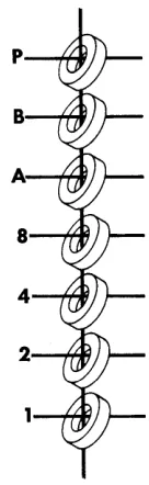
An address refers to the location of a specific char-acter in core storage. The addressing system used by the B 251 System is known as 40-10-12. This means that the total of 4800 character locations in core storage are in effect divided into 40 sections of 10 fields, consisting of 12 characters each. Thus we have a three-character address, AAA, BBB, or GGG, the first character of the address designates the section (Appendix G), the second the field in that section, and the third the character of that field.
When programming, a conversion is necessary in order to obtain the three-character equivalent (AAA) of the four-digit decimal location address (0000 through 4799). This is done by dividing the decimal address by 12. For example, a programmer wants to refer to a character in storage location 3280. Divid-ing 3280 by 12 yields 273 with four remainDivid-ing. This means that the address desired is in the 27th section, so that P (see Appendix G) is the first character of the three-digit address. The division also shows that the location is in the third field of the 27th section and is character position four of that field, thus completing the' address P34.
Note that in counting the sections, fields, and char-acters, the first is always zero, succeeding ones being specific numbers, letters, and characters. For exam-ple, the last two characters of a field are represented by
#
and @ respectively.As indicated by the three addresses represented in the instruction format, the B 251 VRC System is a three-address machine. That is, anyone instruction is capable of referencing up to three storage loca-tions. For example, the Add instruction calls for the addition of the contents of location AAA and BBB, and stores the result in location CCC. Whenever M or N are used to designate a field length, AAA, BBB, or CCC designate the most significant digit of the field.
Not all instructions utilize all 12 character positions. Whenever an address or variant portion of an in-struction is not used, that portion is irrelevant and may be used for storing extra data, such as constants. For example, the No Operation instruction does not use any of its address or variant positions. There-fore, there are 11 character positions available for storing extra data.
INSTRUCTIONS
Operation Name: No Operation " Mnemonic Code: NOP
Operation Code: blank
Instruction Format:
o
M N AAA BBB CCC 0: Operation code blank M: Not usedN: Not used AAA: Not used BBB: Not used CCC: Not used
Perform no operation. Program control continues to the next instruction in sequence. This instruction is generally used as a switch where an address may be inserted in AAA and, under a certain set of circum-stances which dictate that an alternate routine be used, the operation code 9 for a Branch is inserted in the operation code position. The comparison tog-gles (an internal part of the Data Processor checked by the Compare-Branch instruction) are not affected by this instruction.
"Example:
OP M N AAA BBB CCC (No operation is
per-NOP formed)
When used as a switch it would look like this:
OP M N AAA BBB CCC (No operation is
per-NOP 1 XXX formed)
When switch is set to Branch it looks like this:
OP M N AAA BBB CCC (The operation code BRU 1 XXX for the Branch
Uncon-ditional instruction is inserted in the operation code position of the No Operation instruction by the program. The next time this instruction is Refer to BRU instruction. encountered in the
pro-Operation Name: Add
Mnemonic Code: ADD
Operation Code: 1
Instruction Format:
gram, program control will branch to the in-struction stored start-ing at location XXX.)
OM N AAA BBB CCC 0: Operation code 1 M: Length of AAA (1-12)1
N: Length of BBB (1-12)1
AAA: MSD (most significant digit) of augend BBB: MSD of addend
CCC: MSD of sum
Add algebraically the numeric field at location AAA to the numeric field at location BBB, and store the results in location CCC.2 The length of CCC will be the same as AAA or BBB, whichever is larger. Any carry greater than the length of CCC will be lost. The contents of locations AAA and BBB will be undisturbed unless the AAA or BBB address is the same as the CCC address. This instruction will set the comparison toggles to less than zero or minus, zero, or greater than zero or plus, depending on the result of the addition. Minus zero is nonexistent.
1 A zero or blank in either the M or N position denotes a field length of 12. The # denotes a field length of 10; the @ denotes a field length of 11.
2 If alphabetic or special characters are contained in the fields specified by AAA and BBB, only the numeric bits are considered.
Note that in using the Add instruction the field length of CCCmust be large enough to eliminate the possi-bility of the loss of the overflow unless the los's of the overflow is desirable.
Examples:
OP M N AAA
ADD
4 4
100
Contents of
field starting at
100
200
300
100
200
300
100
200
300
OP M N AAA
ADD
3 2
100
Contents of
field starting at
100
200
300
100
200
300
~ M N AAA
ADD
3 3
100
Contents of
field starting at
100
200
100
200
100
200
100
200
*
Overflow lost due to insufficient field length.Operation Name: Subtract Mnemonic Code: SUB Operation Code: 2 Instruction Format
OM N AAA BBB CCC
0: Operation code 2
M: Length of AAA
(1-12)1
N: Length of BBB
(1-12)1
AAA: MSD of minuend field
BBB CCC TOGGLE
200
300
SETTINGSBefore After
0333
0333
0121
0121
0000
0454
Plus8324
8324
7457
7457
3333
5781*
Plus0028
0028
0343
0343
2222
0315
PlusBBB
ccc
200
300
Before After
028
028
62
62
888
034
Minus923
923
88
88
000
011*
PlusBBB
ccc
200
200
Before After
534
534
224
758
Plus735
735
324
059*
Plus028
028
320
292
Plus420
420
050
370'
MinusBBB: MSD of subtrahend field
CCC: MSD of difference field
Subtract algebraically the contents of the numeric field at location BBB from the contents of the nu-meric field at location AAA, and store the results in location CCC.2 The length of CCC is the length of
AAA or BBB address is the same as the CCC
ad-dress. This instruction will set the comparison tog-gles to minus, zero, or plus depending on the result of the subtraction. Minus zero is nonexistent.
Examples:
Note that in using the Subtract instruction the field length of CCC must be large enough to eliminate the possibility of the loss of the overflow unless the loss is desirable.
OP M N AAA BBB
eee
TOGGLESETTINGS
- -
- - -
-SUB 5 5 100 200 300
Contents of Before After
field starting at 100 02315 02315 200 01122 01122
300 99999 01193 Plus 100 83724 83724
200 30324 30324
300 00000 14048* Minus 100 00303 00303
200 00248 00248
300 14048 00551 Plus
OP M N AAA BBB
eee
-SUB 3 3 100 200 100
Contents of Before After
field starting at 100 200 150
200 050 050 Plus
100 755 188*
200 433 433 Minus
100 360 680
200 320 320 Plus
100 234 355
200 121 121 Minus
100 423 048
200 375 375 Minus
Operation Name: Multiply Mnemonic Code: MUL Operation Code: 3 Instruction Format:
o
M N AAA BBB CCC 0: Operation code 3 M: Length of AAA (1-12)1N: Length of BBB
(1-12)1
AAA: MSD of multiplicand field BBB: MSD of multiplier field CCC: MSD of product field
Examples:
Multiply algebraically the contents of the numeric field at location AAA by the contents of the numeric field at location BBB, and store the result or product in the field at location CCC,2 the length of which is M plus N. This instruction will set the comparison toggles to minus, zero, or plus as a result of the multiplication. Multiplication by a negative number which results in a minus zero can occur. A Branch instruction will cause program control to branch on zero, not minus.
OP M N AAA BBB
ccc
TOGGLESETTINGS
MUL
3 2
100
200
300
Operation Name: Divide Mnemonic Code: D IV Operation Code: 4 Instruction Format:
Contents of field starting at
o
M N AAA BBB CCC 0: Operation code 4 M: Length of AAA(1-12)1
N: Length of BBB
(1-12)1
AAA: MSD of dividend field BBB: MSD of divisor field CCC: MSD of quotient field
100
200
300
100
200
300
100
200
300
Divide algebraically the contents of the numeric field at location AAA by the contents of the numeric field at location BBB and store the result in location
Before After
536
536
18
18
82233
09648
Plus810
810
63
63
00000
51030
Minus222
222
44
44
33333
09768
PlusCCC,2 the length of which is M minus N. The re-mainder is stored in location AAA, right justified. Division by zero will result in a quotient of zero and the dividend will not be affected. Any time the absolute value of the divisor field is less than the absolute value of the corresponding high order digits of the dividend, the quotient will be zero and the dividend altered. If M minus N is equal to zero or negative, the machine will halt prior to executing the instruction, and will display the operation code.3 This instruction will set the comparison toggles to minus, zero, or plus as a result of the division. A minus zero quotient can occur on an illegal divide but the Compare-Branch instruction will cause pro-gram control to branch on zero, not minus.
Examples:
.QL M
!i
AAA BBBccc
TOGGLE SETTINGSDIV
4 2
100
200
300
Contents of Before After
field starting at
100
0326
0014
200
24
24
300
00
13
Plus100
2326
*
200
24
24
300
44
00
Zero100
1486
0034
200
44
44
300
85
33
Plus100
1422
1422
200
00
00
300
88
00
Zero*This is an example of an illegal divide. The quotient is zero and the dividend is altered. To divide properly, the MSD of the dividend should be zero, thus making the division legal, as shown in the next example.
OP M N AAA BBB
ccc
TOGGLESETTINGS
DIV
5 2
100
200
300
Contents of field starting at
Operation Name: Compare-Branch Equal Mnemonic Code: CPA, CPZ, CPN Operation Code: 5
Instruction Format:
o
M N AAA BBB CCC 0: Operation code 5 M: 0 Alpha compare (CPA)1 Zone compare (CPZ) 2 Numeric compare (CPN) N: Lengths of AAA and BBB
(1-12)
AAA: MSD of compared field
BBB: MSD of compared field CCC: MSD of Branch address
100
200
300
Compare the contents of location AAA to the con-tents of location BBB and adjust the comparison toggles accordingly. If the contents of location AAA are less than the contents of locationBBB the tog-gles are set to low. If the contents of location
AAA are equal to the contents of location BBB the
toggles are set to equal. If the contents of location AAA are greater than the contents of location BBB the toggles are set to high. If the comparison is
Before After
02326
00022
24
24
444
096
Plusequal, program control will branch to the instruction starting at location CCC,4 otherwise, program con-trol will continue in sequence.
M is the variant which determines the class or type of comparison:
If M equals 0, comparison is made on the alpha-numeric character.
If lVI equals 1, comparison is made on the zone bits only. In this case the collating sequence in ascend-ing! order is
12
zone (A bit),11
zone (B bit), zero zone (A and B bits) and no zone (no A or B bits). For example, on a zone compare, if the A and B bits were on in location AAA and just the A bit was on in location BBB, the comparison toggles would be set to high.If M equals 2, comparison is made on numeric bits only.
The equal status of the comparison toggles will not be disturbed if the branch is taken. The numeric comparison is absolute and signs will be ignored. The results of the alpha comparison are determined by the collating sequence found in Appendix C.
4 Recall that the operation code of an instruction is always stored in the zero (most significant) digit position of a 12-character field.
Examples:
Alphanumeric Comparison:
OP M N AAA BBB CCC TOGGLE
SETTINGS
CPA
0 2
100 200 XXXContents of
field starting at 100 AB 12 AB Zone Comparison Only:
OP M N AAA
CPZ 1 1 100 Contents of
field starting at 100 A A 9 B J BBB 200
200 Branch AB Yes
AB No
JK No
CCC
XXX
200 Branch
G Yes
1 No 8 Yes
K No
K Yes
Equal High Low Equal Low Equal Low Equal
Numeric Comparison Only:
OP M N AAA BBB
ccc
CPN
2 3"
100 200 XXXContents of
field starting at 100 222 ABC ABC
000
JKL JKL OJK(Refer to Appendix C for internal code structure.)
Operation Name: Branch Mnemonic Code: BRC, BRU Operation Code: 6
Instruction Format:
o
M N AAA BBB CCC0:
Operation code 6M: O-Conditional Branch (BRC) 1-Unconditional Branch (BRU) N: Not used
AAA: BRC-Branch address if low or minus BRU--Branch address
BBB: BRC-Branch address if zero or equal BRU-Not used
CCC: BRC-Branch address if high or plus BRU-Not used 200 223 123 Branch No Yes No Yes No Yes Yes Low Equal High Equal Low Equal Equal ABB 000 JKM ABC 18
The Branch instruction with the operation code of 6 is used in two different ways.
When M is 0, the conditional branch calls for chang-ing program control dependchang-ing on the settchang-ing of the comparison toggle.
instruction should immediately follow the arith-metic or Compare instruction upon which the de-cision to branch is to be made. Other instructions affect the comparison toggles and may alter their setting.
When M equals 1, the instruction is an unconditional branch. Program control automatically branches to the instruction starting at location AAA. BBB and CCC are not used.
The comparison toggles are not affected by this in-struction.
Operation Name: Transfer
Mnemonic Code: TFR
Operation Code: 7
Instruction Format:
OM N AAA BBB CCC
0: Operation code 7
M: Number of 12 character fields (0-9) N: Number of remaining characters (0-11) AAA: MSD of field (s) of information to be
trans-ferred BBB: Not used
CCC: MSD of field (s) where information is to be transferred
Relocate alphanumeric data in core storage. Data starting with the contents of location AAA are trans-ferred to another storage area starting with location CCC. The number of characters moved is designated by M and N, where M specifies the number of 12-character fields and N specifies the number of char-acters of a partial field. The maximum number of characters moved by a transfer instruction is 120. Zero or blank in the M or N positions denotes zero except when M and N are both zero, in which case 120 successive characters are transferred. This in-struction does not affect the comparison toggles.
Example:
To relocate 55 characters, starting with the content of location 400, to another storage area starting with location 600, the transfer instruction would be writ-ten as:
7 4 7 400 XXX 600
Starting with the character in location 400 and mov-ing from left to right, the instruction will move 4
fields of 12 characters each plus the next 7 characters for a total of 55 and will place these characters start-ing at location 600, again movstart-ing from left to right.
Operation Name: Mask
Mnemonic Code: MSK
Operation Code: 8
Instruction Format:
o
M N AAA BBB CCC0: Operation code 8
M: Length of AAA (1-12)1 N: Not used
AAA: MSD of field to be masked BBB: MSD of mask constant CCC: MSD of masked field
Move the data starting with the contents of location AAA to a new storage area starting with location CCC, while inserting commas, decimals or credit symbol, and/or performing zero suppression con-trolled by the constant mask located in location BBB. The number of digits in the field to be masked is designated by M. Zero or blank in the M position denotes 12. The length of CCC and BBB is M plus the number of inserts; that is, the length of the original field at AAA as specified by M is increased by the number of inserts specified in the mask field at BBB as it is stored at CCC.
Zero suppression is always operative during this instruction. When high order zeros appear, a char-acter in the Mask field will automatically be inserted until a significant digit in the AAA field is reached.
The character inserted can be a blank for zero sup-pression, an asterisk for check protection, or zero to override zero suppression. When high order zeros are encountered, a comma in the mask field will be replaced by the previously inserted character. A deci-mal point in the mask establishes significance and turns off zero suppression.
Note: The contents of AAA and BBB are not affected by the mask command. Examples below illustrate the contents of AAA and BBB as they would appear before and after execution and the contents of CCC after execution.
OP M N
MSK
6
Contents of field starting at
Operation Name: Halt Mnemonic Code: HLT
Operation Code: 9
Instruction Format:
o
M N AAA BBB CCC 0: Operation code 9M: Halt identification number
AAA
400
400
500
600
400
500
600
400
500
600
400
500
600
400
500
600
BBB
eee
500
600
294736
,
.00-2,947.36
003472
.00-
34.72-000785
0,000.00
Override zero suppression00007.85
006248
$ ,
.00
Insert dollar sign$ 62.48
028735
$*, ***.00
Check Protection$**287.35
AAA: Not used BBB: Not used CCC: Not used
N: HLT-Light 1 of 10 Indicators on Record Processor Console (1-10)
The system halts after all operations in progress have been completed. The Halt indicator on the Record Processor Console, corresponding to N, goes on. The operation code and the M and N variants are dis-played on the Data Processor Console. The compari-son toggles are not affected by this instruction.
Examples:
..QL- M N AAA
!!.!!!!
eee
HLT 0 4Operation Name: Card Read
Mnemonic Code: CRD
Operation Code:
#
Instruction Format:
o
M N AAA BBB CCC0: Operation code
#
M: Not used N: Must be one (1) AAA: Not used
BBB: Branch Address for End of File CCC: MSD of input area
Read the 80 columns of information stored in the card buffer into the 80 positions of core storage start-ing at location CCC. The next card in the Program Card Reader hopper is automatically fed and the 80 columns of information punched in this card is read into the card buffer.
When a card has been incorrectly read, as determined by the read-in checking circuitry, the system halts on the next Card Read instruction and the buffer contents are not transferred to storage.
When a Card Read instruction is to be executed and the buffer has not been refilled due to an empty hopper, the system idles. Depression of the End of File key causes program control to branch to the instruction starting at location BBB. If it is not the end of the file, refill the hopper, then push the Start button on the Program Card Reader and the Con-tinue button on the Data Processor. The comparison toggles are set to zero or equal on this instruction.
Operation Name: Sorter Read, Demand
Mnemonic Code: SRD
Operation Code:
#
Instruction Format:
o
M N AAA BBB CCC0:
Operation code#
M: Not used N: Must be six (6)
AAA: Branch address for "can't read" BBB: Branch address for End of File CCC: MSD of Sorter input area
Transfer information stored in the sorter buffer to core storage. The first location of the input area is designated by CCC. Refilling the buffer is accom-plished automatically by the Control Sorter instruc-tion.
When a "can't read" condition occurs, a binary coded 15 is inserted in place of the invalid charac-teres) and program control branches to the instruc-tion stored in locainstruc-tion AAA.
End of file for the Sorter-Reader in the demand mode is determined by encountering a read instruction when the sorter buffer is empty due to an empty hopper and the system idles. Two courses of action can be taken depending on the conditions which caused the end of file.
1. Refill the sorter hopper and depress the Con-tinue button to conCon-tinue processing.
2. Depress the End of File button and program control will take the end of file branch to the instruction starting at location BBB for the appropriate routine.
The comparison toggles are set to zero or equal on this instruction. Word formatting of MICR informa-tion in storage is covered in Appendix A.
Operation Name: Sorter Read, Flow Mnemonic Code: SRF
Operation Code:
#
Instruction Format:
o
M N AAA BBB CCC0: Operation code
#
M: Not used
N: 4-Read entire document
5-Stop reading at ending transit symbol AAA: Branch address for "can't read"
BBB: Branch address for end of file CCC: MSD of sorter input area
Process MICR documents at flow speed of the sorter, which is up to 1560 items per minute for minimum size documents of 5% inches in length. The charac-ters read from these documents by the Sorter-Reader are transferred directly to core storage. The input area starts at location CCC.
When a "can't read" condition occurs a binary coded 15 is inserted in place of the character(s) that can't be read and program control branches to the instruc-tion stored at locainstruc-tion AAA.
When the Sorter Read, Flow instruction is not pres-ent as the leading edge of the item passes the read head, a stop flow is initiated and this item plus other items in the aligning station will be directed to the reject pocket. The system will halt on the next sorter instruction.
The comparison toggles are set to zero or equal on this instruction.
Word formatting of MICR information in storage is covered in Appendix A.
file is determined. If a stop flow has been initiated either from execution of the Stop Flow instruction or from a signal sent from the batch ticket detecting de-vice of the Sorter-Reader and the items in the trans-port have been processed, program control will take the end of file branch to the instruction starting at location BBB for the appropriate routine. If the system halts because no document has been fed, two courses of action can be taken depending on the conditions which caused the halt.
1. Refill the sorter hopper and depress the Con-tinue button to conCon-tinue processing.
2. Depress the End of File button and program control will take the end of file branch (BBB). Operation Name: Control Sorter
Mnemonic Code: CTL Operation Code: C Instruction Format:
o
M N AAA BBB CCC0: Operation code C
M: Determines type of control O-Pocket Select only
2-Demand feed one item and pocket select
4-Stop flow mode and pocket select 6-Start or continue flow and pocket select N: Select pocket (0-11, 15)5
AAA: Not used
BBB: Not used CCC: Not used
Control the sorter according to the variant M and select the pocket designated by N. This instruction only controls the feeding, pocket selecting and eject-" ing of items. When M is 2, one item will be fed, transferred to the buffer, and stopped at the stand-by station. A pocket will be selected and the item previ-ously at the stand-by station sent to that pocket. When M is 6, the flow of items is either started or continued. Information from the items is transferred directly to storage by execution of a Read Sorter instruction.
In the demand mode a Control Sorter instruction cannot be executed when the buffer is still full. The system will halt. A read instruction must be given prior to each Control Sorter instruction.
In the flow mode, if a Control Sorter instruction is not executed within 29 ms. after the start of a Read Sorter instruction, the sorter will shut down and the system will halt.
For each item fed by the sorter, one Read Sorter and one Control Sorter instruction must be executed or the system will halt.
The comparison toggles are set to zero or equal on this instruction.
Operation Name: Record Processor Read Mnemonic Code: RPR
Operation Code: G Instruction Format:
o
M N AAA BBB CCC0: Operation code G M: 1-Primary station
2-Manual station 3-Auxiliary station N: Not used
AAA: Branch address on read error or feed of multiple documents
BBB: Not used and not available for storing extra data
CCC: MSD of inpu~ storage area
Pick a record from the station designated by M, feed it and read 81 characters of information from the magnetic stripe. Store the information in an input area starting with location CCC. The 81st character is a special character called a group mark ($) which will signal the end of the read. The group mark is stored.
In the event of a read or double document error the records will be directed to the auxiliary stacker and the system will halt. Depression of the Continue button on the Console causes program control to branch to the instruction starting at AAA for the appropriate error routine.
When M is 4 or 5 this instruction can perform additional operations which utilize the N, AAA, BBB, and CCC character positions for different pur-poses than above.
M: 4-Auxiliary station and photo sensing N: Not used
AAA: Not used BBB: Not used
CCC: MSD of input storage area
Pick a record from the auxiliary station. Read the two digIts of information (bar code) encoded on the face of the record into storage locations CCC and CCC
+
1.M: 5-Keyboard
N: Light indicators on Keyboard (1-10) AAA: Not used
BBB: Not used
CCC: MSD of input storage area
Read 13 digits indexed on the Keyboard (12 nu-merlc and one special data) into a storage area start-ing with location
eec.
The instruction will also light the Keyboard indicator corresponding to N.(See Entry Control Key, Section 5.)
The comparison toggles are set to zero or equal on this instruction.
Operation Name: Record Processor Write and Eject
Mnemonic Code: RPW
Operation Code: G
Instruction Format:
o
M N AAA BBB CCC0: Operation code G M: 8-Eject and write
N: 0-Primary stacker I-Auxiliary stacker AAA: MSD of storage area BBB: Not used
eee:
Branch address on write errorEject the record in the print station to the stacker designated by N and write the information starting from location AAA in the record stripe. If a write error condition occurs, the record is directed to the auxiliary stacker and the system halts. Depression of the Continue button causes program control to branch to the instruction starting at location
cec
for the proper error routine. Eighty-one characters are written from storage to the magnetic stripe. The 81st character is the group mark which signals the end of the information to be written.M: 9-Eject only N: O-Primary stacker
I-Auxiliary stacker AAA: Not used
BBB: -Not used CCC: Not used
Eject the record in the print station to the stacker designated by N without storing new information in the record stripe. The eject instruction must be pre-ceded by an a1ign or print instruction.
The comparison toggles are set to zero or equal on this instruction.
Operation Name: Record Processor Print
Mnemonic Code: PRY
Operation Code: H
Instruction Format:
o
M N AAA BBB CCC0: Operation code H M: Not used
N: O-Space suppress I-Space form A 2-Space form B
3-Space forms A and B 4-Space record
5-Space record and form A 6-Space record and form B 7-Space record, forms A and B AAA: MSD of storage area printed from BBB: Branch address for form B last line
cce:
Branch address on print errorPrint one line of 156 characters from 160 locations in storage starting with the character in location AAA. Four positions will be occupied by dummy print bars for the purpose of supporting the ribbon. Blanks must be inserted in storage corresponding to these positions! Single space the record and forms, after printing, according to variant N.
If during execution of this instruction the last line is printed on form B, program control branches to the instruction starting at location BBB.
When a print instruction is to be executed and the line find mechanism has failed to operate, the system will halt and the Align eheck indicator on the con-sole goes on. The record proceeds to the primary stacker. Depression of the Continue button will cause the next instruction in sequence to be executed.
If a print error occurs, the system halts and spacing is suppressed. When the Continue button is de-pressed, program control transfers to the instruction starting at location CCC. A branch on print error takes precedence over a form B last line branch.
At the completion of the print instruction the com-parison toggles are in the zero or equal state.
Operation Name: Skip Record Processor
Instruction Format:
o
M N AAA BBB CCC0: Operation code I M: l-Restore forms only
2-Single space forms and ledger according to variant N
4-Align record N: l-Space form A
2-Space form B
3-Space forms A and B 4-Space ledger
5-Space1.edger and form A 6-Space ledger and form B
7-Space ledger and forms A and B AAA: Address of MSD of line find digits when
M is 4. Otherwise not used.
SAMPLE PROBLEM
For a sample program using most of the instructions, a simple bank account updating application was selected. With the program is the flow chart from which the program was developed, a list of the stor-age location assignments, a memory map showing the individual assignment in storage, and the input and output layout forms.
A simple addressing system was employed in the sample for clarity and better understanding. The three characters of the address, separated by
deci-YES
BBB: Branch address of Form B last line. CCC: Not used
Controls form spacing or skipping on the Record Processor according to variants M and N.
When M is four, the last record fed will be stopped in the printer at the print line (0-47) specified by the line find information stored starting at location AAA. This information is either previously read from the magnetic strip for storage or is prestored.
If an align instruction is given too late to stop the record in the print station, the align instruction will not be executed. The system will halt and the record will go directly to the primary stacker. The Align Check indicator will light.
At completion of this instruction the comparison toggles are set to zero or equal.
mal points, represent the section, field, and charac-ter, respectively, of the location. For example, 7.1.5 means the 5th character location in the first field of the seventh section.
It is assumed in the sample that the transaction code on a check is blank and on a deposit is one. It was arbitrarily decided to use XXX for the branch ad-dresses for can't read, end of file, read error, invalid transaction code, other item routine, form B last line, print error, write error, and overdrawn account routine.
TO OVERDRAWN REPORT
LOCATION ASSIGNMENT
Instructions ... . 0.0.0 Item Input Area ... . 3.0.0
Account number, M.S.D. - Length - 7 ... . 3.4.5 Transaction Code, M.S.D. - Length - 1. ... ,' ... . 3.5.@ Amount, M.S.D. - Length - 10 ... . 3.6.1
Account Record Input Area ... . 4.0.0 Line Final Data, M.S.D. - Length - 2 ... . 4.0.0
Account number, M.S.D. - Length - 7 ... . 4.0.2 Balance, M.S.D. - Length -12 ... . 4.1.0
Printer Output Area ... . 5.0.0 Checks, M.S.D ... . 5.2.5
Deposits, M.S.D ... . 5.3.# Date, M.S.D ... . 5.5.3 Balance, M.S.D ... . 5.6.5
Blank Area for Clearing ... . 6.0.0 Constant Area ... . 7.0.0
Mask, M.S.D ... . 7.0.0 Date, M.S.D. - Length - 7 ... . 7.1.5
SAMPLE PROGRAM
LOC MNE OP M N AAA BBB CCC REMARKS
0.0.0 SRD # 6
XXX
XXX
3.0.0 Read first item. 0.1.0 RPR G 1XXX
4.0.0 Read account record.0.2.0 CPN 5 2 7 4.0.2 3.4.5 0.4.0 Are item and record account number equal?
0.3.0 BRU 6 1 0.1.0 To read next record.
0.4.0 SKR I 4 4.0.0 Align record specified by line find. 0.5.0 CPA 5 0 1 3.5.@ 0.1.2 1.2.0' Is this item a check? T .C. = blank. 0.6.0 CPA 5 0 1 3.5.@ 0.6.2 0.8.0 Is this item a deposit? T.C. = 1.
0.7.0 BRC 6 0
XXX
XXX
To error and other item routine. 0.8.0 MSK 8 # 3.6.1 7.0.3 5.3.# Mask deposit amount to print area. 0.9.0 ADD 1 # 0 3.6.1 4.1.0 4.1.0 Increase balance.1.0.0 CTL C 2 2 Eject deposit to pocket 2.
1.1.0 BRU 6 1 1.5.0 To read next item.
1.2.0 MSK 8 # 3.6.1 7.0.3 5.2.5 Mask check amount to print area. 1.3.0 SUB 2 0 # 4.1.0 3.6.1 4.1.0 Reduce ba