NONRESIDENT
TRAINING
COURSE
SEPTEMBER 1998
Navy Electricity and
Electronics Training Series
Module 12—Modulation
DISTRIBUTION STATEMENT A: Approved for public release; distribution is unlimited. Although the words “he,” “him,” and
PREFACE
By enrolling in this self-study course, you have demonstrated a desire to improve yourself and the Navy. Remember, however, this self-study course is only one part of the total Navy training program. Practical experience, schools, selected reading, and your desire to succeed are also necessary to successfully round out a fully meaningful training program.
COURSE OVERVIEW: To introduce the student to the subject of Modulation Principles who needs
such a background in accomplishing daily work and/or in preparing for further study.
THE COURSE: This self-study course is organized into subject matter areas, each containing learning
objectives to help you determine what you should learn along with text and illustrations to help you understand the information. The subject matter reflects day-to-day requirements and experiences of personnel in the rating or skill area. It also reflects guidance provided by Enlisted Community Managers (ECMs) and other senior personnel, technical references, instructions, etc., and either the occupational or naval standards, which are listed in the Manual of Navy Enlisted Manpower Personnel Classifications and Occupational Standards, NAVPERS 18068.
THE QUESTIONS: The questions that appear in this course are designed to help you understand the
material in the text.
VALUE: In completing this course, you will improve your military and professional knowledge. Importantly, it can also help you study for the Navy-wide advancement in rate examination. If you are studying and discover a reference in the text to another publication for further information, look it up.
1998 Edition Prepared by ETCM Danny K. Krutson
Published by
NAVAL EDUCATION AND TRAINING PROFESSIONAL DEVELOPMENT
AND TECHNOLOGY CENTER
Sailor’s Creed
“I am a United States Sailor.
I will support and defend the
Constitution of the United States of
America and I will obey the orders
of those appointed over me.
I represent the fighting spirit of the
Navy and those who have gone
before me to defend freedom and
democracy around the world.
I proudly serve my country’s Navy
combat team with honor, courage
and commitment.
TABLE OF CONTENTS
CHAPTER PAGE
1. Amplitude Modulation ... 1-1
2. Angle and Pulse Modulation ... 2-1
3. Demodulation ... 3-1
APPENDIX
I. Glossary... AI-1
NAVY ELECTRICITY AND ELECTRONICS TRAINING
SERIES
The Navy Electricity and Electronics Training Series (NEETS) was developed for use by personnel in many electrical- and electronic-related Navy ratings. Written by, and with the advice of, senior technicians in these ratings, this series provides beginners with fundamental electrical and electronic concepts through self-study. The presentation of this series is not oriented to any specific rating structure, but is divided into modules containing related information organized into traditional paths of instruction. The series is designed to give small amounts of information that can be easily digested before advancing further into the more complex material. For a student just becoming acquainted with electricity or electronics, it is highly recommended that the modules be studied in their suggested sequence. While there is a listing of NEETS by module title, the following brief descriptions give a quick overview of how the individual modules flow together.
Module 1, Introduction to Matter, Energy, and Direct Current, introduces the course with a short history
of electricity and electronics and proceeds into the characteristics of matter, energy, and direct current (dc). It also describes some of the general safety precautions and first-aid procedures that should be common knowledge for a person working in the field of electricity. Related safety hints are located throughout the rest of the series, as well.
Module 2, Introduction to Alternating Current and Transformers, is an introduction to alternating current
(ac) and transformers, including basic ac theory and fundamentals of electromagnetism, inductance, capacitance, impedance, and transformers.
Module 3, Introduction to Circuit Protection, Control, and Measurement, encompasses circuit breakers,
fuses, and current limiters used in circuit protection, as well as the theory and use of meters as electrical measuring devices.
Module 4, Introduction to Electrical Conductors, Wiring Techniques, and Schematic Reading, presents
conductor usage, insulation used as wire covering, splicing, termination of wiring, soldering, and reading electrical wiring diagrams.
Module 5, Introduction to Generators and Motors, is an introduction to generators and motors, and
covers the uses of ac and dc generators and motors in the conversion of electrical and mechanical energies.
Module 6, Introduction to Electronic Emission, Tubes, and Power Supplies, ties the first five modules
together in an introduction to vacuum tubes and vacuum-tube power supplies.
Module 7, Introduction to Solid-State Devices and Power Supplies, is similar to module 6, but it is in
reference to solid-state devices.
Module 8, Introduction to Amplifiers, covers amplifiers.
Module 9, Introduction to Wave-Generation and Wave-Shaping Circuits, discusses wave generation and
wave-shaping circuits.
Module 10, Introduction to Wave Propagation, Transmission Lines, and Antennas, presents the
Module 11, Microwave Principles, explains microwave oscillators, amplifiers, and waveguides. Module 12, Modulation Principles, discusses the principles of modulation.
Module 13, Introduction to Number Systems and Logic Circuits, presents the fundamental concepts of
number systems, Boolean algebra, and logic circuits, all of which pertain to digital computers.
Module 14, Introduction to Microelectronics, covers microelectronics technology and miniature and
microminiature circuit repair.
Module 15, Principles of Synchros, Servos, and Gyros, provides the basic principles, operations,
functions, and applications of synchro, servo, and gyro mechanisms.
Module 16, Introduction to Test Equipment, is an introduction to some of the more commonly used test
equipments and their applications.
Module 17, Radio-Frequency Communications Principles, presents the fundamentals of a
radio-frequency communications system.
Module 18, Radar Principles, covers the fundamentals of a radar system.
Module 19, The Technician's Handbook, is a handy reference of commonly used general information,
such as electrical and electronic formulas, color coding, and naval supply system data.
Module 20, Master Glossary, is the glossary of terms for the series.
Module 21, Test Methods and Practices, describes basic test methods and practices. Module 22, Introduction to Digital Computers, is an introduction to digital computers.
Module 23, Magnetic Recording, is an introduction to the use and maintenance of magnetic recorders and
the concepts of recording on magnetic tape and disks.
Module 24, Introduction to Fiber Optics, is an introduction to fiber optics.
Embedded questions are inserted throughout each module, except for modules 19 and 20, which are reference books. If you have any difficulty in answering any of the questions, restudy the applicable section.
Although an attempt has been made to use simple language, various technical words and phrases have necessarily been included. Specific terms are defined in Module 20, Master Glossary.
Considerable emphasis has been placed on illustrations to provide a maximum amount of information. In some instances, a knowledge of basic algebra may be required.
Throughout the text of this course and while using technical manuals associated with the equipment you will be working on, you will find the below notations at the end of some paragraphs. The notations are used to emphasize that safety hazards exist and care must be taken or observed.
WARNING
AN OPERATING PROCEDURE, PRACTICE, OR CONDITION, ETC., WHICH MAY RESULT IN INJURY OR DEATH IF NOT CAREFULLY OBSERVED OR FOLLOWED.
CAUTION
AN OPERATING PROCEDURE, PRACTICE, OR CONDITION, ETC., WHICH MAY RESULT IN DAMAGE TO EQUIPMENT IF NOT CAREFULLY OBSERVED OR FOLLOWED.
NOTE
INSTRUCTIONS FOR TAKING THE COURSE
ASSIGNMENTS
The text pages that you are to study are listed at the beginning of each assignment. Study these pages carefully before attempting to answer the questions. Pay close attention to tables and illustrations and read the learning objectives. The learning objectives state what you should be able to do after studying the material. Answering the questions correctly helps you accomplish the objectives.
SELECTING YOUR ANSWERS
Read each question carefully, then select the BEST answer. You may refer freely to the text. The answers must be the result of your own work and decisions. You are prohibited from referring to or copying the answers of others and from giving answers to anyone else taking the course.
SUBMITTING YOUR ASSIGNMENTS
To have your assignments graded, you must be enrolled in the course with the Nonresident Training Course Administration Branch at the Naval Education and Training Professional Development and Technology Center (NETPDTC). Following enrollment, there are two ways of having your assignments graded: (1) use the Internet to submit your assignments as you complete them, or (2) send all the assignments at one time by mail to NETPDTC.
Grading on the Internet: Advantages to
Internet grading are:
• you may submit your answers as soon as you complete an assignment, and
• you get your results faster; usually by the next working day (approximately 24 hours).
In addition to receiving grade results for each assignment, you will receive course completion confirmation once you have completed all the
assignments. To submit your assignment answers via the Internet, go to:
http://courses.cnet.navy.mil
Grading by Mail: When you submit answer
sheets by mail, send all of your assignments at one time. Do NOT submit individual answer sheets for grading. Mail all of your assignments in an envelope, which you either provide yourself or obtain from your nearest Educational Services Officer (ESO). Submit answer sheets to:
COMMANDING OFFICER NETPDTC N331
6490 SAUFLEY FIELD ROAD PENSACOLA FL 32559-5000
Answer Sheets: All courses include one “scannable” answer sheet for each assignment. These answer sheets are preprinted with your SSN, name, assignment number, and course number. Explanations for completing the answer sheets are on the answer sheet.
Do not use answer sheet reproductions: Use
only the original answer sheets that we provide—reproductions will not work with our scanning equipment and cannot be processed.
Follow the instructions for marking your answers on the answer sheet. Be sure that blocks 1, 2, and 3 are filled in correctly. This information is necessary for your course to be properly processed and for you to receive credit for your work.
COMPLETION TIME
PASS/FAIL ASSIGNMENT PROCEDURES
If your overall course score is 3.2 or higher, you will pass the course and will not be required to resubmit assignments. Once your assignments have been graded you will receive course completion confirmation.
If you receive less than a 3.2 on any assignment and your overall course score is below 3.2, you will be given the opportunity to resubmit failed assignments. You may resubmit failed assignments only once. Internet students will
receive notification when they have failed an assignment--they may then resubmit failed assignments on the web site. Internet students may view and print results for failed assignments from the web site. Students who submit by mail will receive a failing result letter and a new answer sheet for resubmission of each failed assignment.
COMPLETION CONFIRMATION
After successfully completing this course, you will receive a letter of completion.
ERRATA
Errata are used to correct minor errors or delete obsolete information in a course. Errata may also be used to provide instructions to the student. If a course has an errata, it will be included as the first page(s) after the front cover. Errata for all courses can be accessed and viewed/downloaded at:
http://www.advancement.cnet.navy.mil
STUDENT FEEDBACK QUESTIONS
We value your suggestions, questions, and criticisms on our courses. If you would like to communicate with us regarding this course, we encourage you, if possible, to use e-mail. If you write or fax, please use a copy of the Student Comment form that follows this page.
For subject matter questions:
E-mail: [email protected] Phone: Comm: (850) 452-1001, ext. 1728
DSN: 922-1001, ext. 1728 FAX: (850) 452-1370 (Do not fax answer sheets.) Address: COMMANDING OFFICER
NETPDTC N315
6490 SAUFLEY FIELD ROAD PENSACOLA FL 32509-5237
For enrollment, shipping, grading, or completion letter questions
E-mail: [email protected] Phone: Toll Free: 877-264-8583
Comm: (850) 452-1511/1181/1859 DSN: 922-1511/1181/1859
FAX: (850) 452-1370 (Do not fax answer sheets.) Address: COMMANDING OFFICER
NETPDTC N331
6490 SAUFLEY FIELD ROAD PENSACOLA FL 32559-5000
NAVAL RESERVE RETIREMENT CREDIT
Student Comments
Course Title:
NEETS Module 12
Modulation Principles
NAVEDTRA:
14184
Date:
We need some information about you:
Rate/Rank and Name: SSN: Command/Unit
Street Address: City: State/FPO: Zip
Your comments, suggestions, etc.:
Privacy Act Statement: Under authority of Title 5, USC 301, information regarding your military status is requested in processing your comments and in preparing a reply. This information will not be divulged without written authorization to anyone other than those within DOD for official use in determining performance.
CHAPTER 1
AMPLITUDE MODULATION
LEARNING OBJECTIVES
Learning objectives are stated at the beginning of each chapter. These learning objectives serve as a preview of the information you are expected to learn in the chapter. The comprehensive check questions are based on the objectives. By successfully completing the OCC/ECC, you indicate that you have met the objectives and have learned the information. The learning objectives are listed below.
Upon completion of this chapter, you will be able to:
1. Discuss the generation of a sine wave by describing its three characteristics: amplitude, phase, and frequency.
2. Describe the process of heterodyning.
3. Discuss the development of continuous-wave (cw) modulation. 4. Describe the two primary methods of cw communications keying. 5. Discuss the radio frequency (rf) spectrum usage by cw transmissions. 6. Discuss the advantages and disadvantages of cw transmissions. 7. Explain the operation of typical cw transmitter circuitry.
8. Discuss the method of changing sound waves into electrical impulses. 9. Describe the rf usage of an AM signal.
10. Calculate the percent of modulation for an AM signal.
11. Discuss the difference between high- and low-level modulation.
12. Describe the circuit description, operation, advantages, and disadvantages of the following common AM tube/transistor modulating circuits: plate/collector, control grid/base, and cathode/emitter.
13. Discuss the advantages and disadvantages of AM communications.
INTRODUCTION TO MODULATION PRINCIPLES
As the potential for the uses of electricity were explored, scientists in the United States and England worked to develop the telegraph. The first practical system was established in London, England, in 1838. Just 20 years later, the final link to connect the major countries with electrical communications was completed when a transatlantic submarine cable was connected. Commercial telegraphy was practically worldwide by 1890. The telegraph key, wire lines, and Morse code made possible almost instantaneous communications between points at great distances. Submarine cables solved the problems of transoceanic communications, but communications with ships at sea and mobile forces were still poor.
In 1897 Marconi demonstrated the first practical wireless transmitter. He sent and received messages over a distance of 8 miles. By 1898 he had demonstrated the usefulness of wireless telegraph
communications at sea. In 1899 he established a wireless telegraphic link across the English Channel. His company also established general usage of the wireless telegraph between coastal light ships (floating lighthouses) and land. The first successful transatlantic transmissions were achieved in 1902. From that time to the present, radio communication has grown at an extraordinary rate. Early systems transmitted a few words per minute with doubtful reliability. Today, communications systems reliably transmit information across millions of miles.
The desire to communicate directly by voice, at a higher rate of speed than possible through basic telegraphy, led to further research. That research led to the development of MODULATION. Modulation is the ability to impress intelligence upon a TRANSMISSION MEDIUM, such as radio waves. A
transmission medium can be described as light, smoke, sound, wire lines, or radio-frequency waves. In this module, you will study the basic principles of modulation and DEMODULATION (removing intelligence from the medium).
In your studies, you will learn about modulation as it applies to radio-frequency communications. To modulate is to impress the characteristics (intelligence) of one waveform onto a second waveform by varying the amplitude, frequency, phase, or other characteristics of the second waveform. First, however, you will review the characteristics and generation of a sine wave. This review will help you to better understand the principles of modulation. Then, an important principle called HETERODYNING (mixing two frequencies across a nonlinear impedance) will be studied and applied to modulation. Nonlinear impedance will be discussed in the heterodyning section. You will also study several methods of modulating a radio-frequency carrier. You will come to a better understanding of the demodulation principle by studying the various circuits used to demodulate a modulated carrier.
Q-1. What is modulation?
Q-2. What is a transmission medium? Q-3. What is heterodyning?
Q-4. What is demodulation?
SINE WAVE CHARACTERISTICS
GENERATION OF SINE WAVES
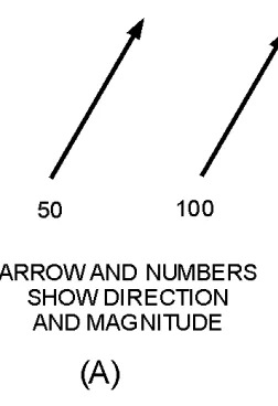
Since numbers represent individual items in a group, arrows can be used to represent quantities that have magnitude and direction. This may be done by using an arrow and a number, as illustrated in figure 1-1, view (A). The number represents the magnitude of force and the arrow represents the direction of the force.
Figure 1-1A.—Vectors representing magnitude and direction.
View (B) illustrates a simpler method of representation. In this method, the length of the arrow is proportional to the magnitude of force, and the direction of force is indicated by the direction of the arrow. Thus, if an arrow 1-inch long represents 50 pounds of force, then an arrow 2-inches long would represent 100 pounds of force. This method of showing both magnitude and direction is called a
VECTOR. To more clearly show the relationships between the amplitude, phase, and frequency of a sine wave, we will use vectors.
[image:15.612.241.367.160.344.2]+
Vector Applied to Sine-Wave Generation
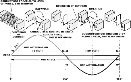
[image:16.612.80.536.180.465.2]As covered, in NEETS, Module 2, Introduction to Alternating Current and Transformers, an alternating current is generated by rotating a coil in the magnetic field between two magnets. As long as the magnetic field is uniform, the output from the coil will be a sine wave, as shown in figure 1-2. This wave shape is called a sine wave because the voltage of the coil depends on its angular position in the magnetic field.
Figure 1-2.—Sine-wave generator.
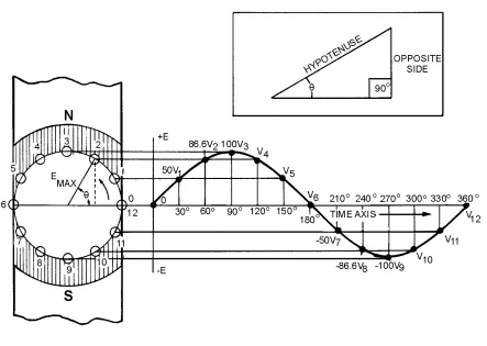
You should recall that the trigonometric ratio (inset in figure 1-3) for the sine in a right triangle (a triangle in which one angle is 90 degrees) is:
When an alternating waveform is generated, the coil is represented by a vector which has a length that is equal to the maximum output voltage (Emax). The output voltage at any given angle can be found by applying the above trigonometric function. Because the output voltage is in direct relationship with the sine of the angle !, it is commonly called a sine wave.
You can see this relationship more clearly in figure 1-3 where the coil positions in relation to time are represented by the numbers 0 through 12. The corresponding angular displacements, shown as !, are shown along the horizontal time axis. The induced voltages (V1 through V12) are plotted along this axis. Connecting the induced voltage points, shown in the figure, forms a sine-wave pattern. This relationship can be proven by taking any coil position and applying the trigonometric function to an equivalent right triangle. When the vector is placed horizontally (position 0), the angle ! is 0 degrees. Since e = Emax sine
Figure 1-3.—Generation of sine-wave voltage.
At position 2, the sine of 60 degrees is 0.866 and an output of 86.6 volts is developed.
This relationship is plotted through 360 degrees of rotation. A continuous line is drawn through the successive points and is known as 1 CYCLE of a sine wave. If the time axis were extended for a second revolution of the vector plotted, you would see 2 cycles of the sine wave. The 0-degree point of the second cycle would be the same point as the 360-degree point of the first cycle.
Q-5. What waveform is the basis of all complex waveforms? Q-6. What is the purpose of using vectors?
Q-8. What is the mathematical formula for computing the output voltage from a moving coil in a magnetic field?
AMPLITUDE
A sine wave is used to represent values of electrical current or voltage. The greater its height, the greater the value it represents. As you have studied, a sine wave alternately rises above and then falls below the reference line. That part above the line represents a positive value and is referred to as a POSITIVE ALTERNATION. That part of the cycle below the line has a negative value and is referred to as a NEGATIVE ALTERNATION. The maximum value, above or below the reference line, is called the PEAK AMPLITUDE. The value at any given point along the reference line is called the
INSTANTANEOUS AMPLITUDE.
PHASE
PHASE or PHASE ANGLE indicates how much of a cycle has been completed at any given instant. This merely describes the angle that exists between the starting point of the vector and its position at that instant. The number of degrees of vector rotation and the number of degrees of the resultant sine wave that have been completed will be the same. For example, at time position 2 of figure 1-3, the vector has rotated to 60 degrees and 60 degrees of the resultant sine wave has been completed. Therefore, both are said to have an instantaneous phase angle of 60 degrees.
FREQUENCY
The rate at which the vector rotates determines the FREQUENCY of the sine wave that is generated; that is, the faster the vector rotates, the more cycles completed in a given time period. The basic time period used is 1 second. If a vector completes one revolution per 1 second, the resultant sine wave has a frequency 1 cycle per second (1 hertz). If the rate of rotation is increased to 1,000 revolutions per second, the frequency of the sine wave generated will be 1,000 cycles per second (1 kilohertz).
PERIOD
WAVELENGTH
The WAVELENGTH of a sine wave is determined by its physical length. During the period a wave is being generated, its leading edge is moving away from the source at 300,000,000 meters per second. The physical length of the sine wave is determined by the amount of time it takes to complete one full cycle. This wavelength is an important factor in determining the size of equipments used to generate and transmit radio frequencies.
To help you understand the magnitude of the distance a wavefront (the initial part of a wave) travels during 1 cycle, we will compute the wavelengths (l;) of several frequencies. Consider a vector that rotates at 1 revolution per second. The resultant sine wave is transmitted into space by an antenna. As the vector moves from its 0-degree starting position, the wavefront begins to travel away from the antenna. When the vector reaches the 360-degree position, and the sine wave is completed, the sine wave is stretched out over 300,000,000 meters. The reason the sine wave is stretched over such a great distance is that the wavefront has been moving away from the antenna at 300,000,000 meters per second. This is shown in the following example:
If a vector were rotating at 1,000 revolutions per second, its period would be 0.001 second. By applying the formula for wavelength, you would find that the wavelength is 300,000 meters:
Thus, for a sine wave with a frequency of 1,000,000 hertz (1 megahertz), the wavelength would be 300 meters, as shown below:
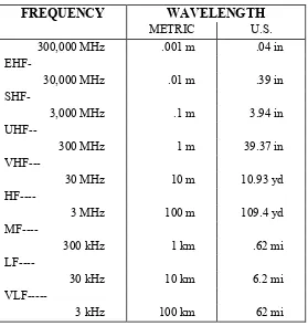
[image:21.612.176.455.301.596.2]The higher the frequency, the shorter the wavelength of a sine wave. This important relationship between frequency and wavelength is illustrated in table 1-1.
Table 1-1.—Radio frequency versus wavelength
FREQUENCY WAVELENGTH
METRIC U.S. 300,000 MHz .001 m .04 in EHF-
30,000 MHz .01 m .39 in SHF-
3,000 MHz .1 m 3.94 in UHF--
300 MHz 1 m 39.37 in VHF---
30 MHz 10 m 10.93 yd HF----
3 MHz 100 m 109.4 yd MF----
300 kHz 1 km .62 mi LF----
30 kHz 10 km 6.2 mi VLF---
3 kHz 100 km 62 mi
Q-9. What is the instantaneous amplitude of a sine wave?
Q-10. What term describes how much of a cycle has been completed? Q-11. What determines the frequency of a sine wave?
Q-13. How do you calculate the wavelength of a sine wave?
HETERODYNING
Information waveforms are produced by many different sources and are generally quite low in frequency. A good example is the human voice. The frequencies involved in normal speech vary from one individual to another and cover a wide range. This range can be anywhere from a low of about 90 hertz for a deep bass to as high as 10 kilohertz for a high soprano.
The most important speech frequencies almost entirely fall below 3 kilohertz. Higher frequencies merely help to achieve more perfect sound production. The range of frequencies used to transmit voice intelligence over radio circuits depends on the degree of FIDELITY (the ability to faithfully reproduce the input in the output) that is desired. The minimum frequency range that can be used for the transmission of speech is 500 to 2,000 hertz. The average range used on radiotelephone circuits is 250 to 2,750 hertz.
Frequencies contained within the human voice can be transmitted over telephone lines without difficulty, but transmitting them via radio circuits is not practical. This is because of their extremely long wavelengths and the fact that antennas would have to be constructed with long physical dimensions to transmit or radiate these wavelengths. Generally, antennas have radiating elements that are 1/4, 1/2, 1, or more full wavelengths of the frequency to be radiated. The wavelengths of voice frequencies employed on radiotelephone circuits range from 1,200,000 meters at 250 hertz to 109,090 meters at 2,750 hertz. Even a quarter-wave antenna would require a large area, be expensive to construct, and consume enormous amounts of power.
As studied in NEETS, Module 10, Introduction to Wave Propagation, Transmission Lines, and Antennas, radio frequencies do not have the limitations just described for voice frequencies. Radio waves, given a suitable antenna, can often radiate millions of miles into space. Several methods of modulation can be used to impress voices frequencies onto radio waves for transmission through space.
In the modulation process, waves from the information source are impressed onto a radio-frequency sine wave called a CARRIER. This carrier is sufficiently high in frequency to have a wavelength short enough to be radiated from an antenna of practical dimensions. For example, a carrier frequency of 10 megahertz has a wavelength of 30 meters, as shown below:
Construction of an antenna related to that wavelength does not cause any problems.
is referred to as the MODULATED WAVE and is the waveform that is transmitted through space. When the modulated wave is received and demodulated, the original component waves (carrier and modulating waves) are reproduced with their respective frequencies, phases, and amplitudes unchanged.
Modulation of a carrier can be achieved by any of several methods. Generally, the methods are named for the sine-wave characteristic that is altered by the modulation process. In this module, you will study AMPLITUDE MODULATION, which includes CONTINUOUS-WAVE MODULATION. You will also learn about two forms of ANGLE MODULATION (FREQUENCY MODULATION and PHASE MODULATION). A special type of modulation, known as PULSE MODULATION, will also be discussed. Before we present the methods involved in developing modulation, you need to study a process that is essential to the modulation of a carrier, known as heterodyning.
To help you understand the operation of heterodyning circuits, we will begin with a discussion of LINEAR and NONLINEAR devices. In linear devices, the output rises and falls directly with the input. In nonlinear devices, the output does not rise and fall directly with the input.
LINEAR IMPEDANCE
Whether the impedance of a device is linear or nonlinear can be determined by comparing the change in current through the device to the change in voltage applied to the device. The simple circuit shown in view (A) of figure 1-4 is used to explain this process.
Figure 1-4A.—Circuit with one linear impedance.
First, the current through the device must be measured as the voltage is varied. Then the current and voltage values can be plotted on a graph, such as the one shown in view (B), to determine the impedance of the device. For example, assume the voltage is varied from 0 to 200 volts in 50-volt steps, as shown in view (B). At the first 50-volt point, the ammeter reads 0.5 ampere. These ordinates are plotted as point a
Figure 1-4B.—Circuit with one linear impedance.
The principle of linear impedance can be extended by connecting two impedance devices in series, as shown in figure 1-5, view (A). The characteristics of both individual impedances are determined as explained in the preceding section. For example, assume voltmeter V1 shows 50 volts and the ammeter shows 0.5 ampere. Point a in view (B) represents this ordinate. In the same manner, increasing the voltage in increments of 50 volts gives points b, c, and d. Lines Z1 and Z2 show the characteristics of the two impedances. The total voltage of the series combination can be determined by adding the voltages across Z1 and Z2. For example, at 0.5 ampere, point a (50 volts) plus point e (75 volts) produces point i (125 volts). Also, at 1 ampere, point b plus point f produces point j. Line Z1 + Z2 represents the combined voltage-current characteristics of the two devices.
Figure 1-5B.—Circuit with two linear impedances.
Figure 1-6.—Circuit with parallel linear impedances.
Positive or negative voltage values can be used to plot the voltage-current graph. Figure 1-7 shows an example of this situation. First, the voltage versus current is plotted with the battery polarity as shown in view (A). Then the battery polarity is reversed and the remaining voltage versus current points are plotted. As a result, the line shown in view (C) is obtained.
Figure 1-7B.—Linear impedance circuit.
Figure 1-7C.—Linear impedance circuit
The battery in view (A) could be replaced with an ac generator, as shown in view (B), to plot the characteristic chart. The same linear voltage-current chart would result. Current flow in either direction is directly proportional to the change in voltage.
In conclusion, when dc or sine-wave voltages are applied to a linear impedance, the current through the impedance will vary directly with a change in the voltage. The device could be a resistor, an air-core inductor, a capacitor, or any other linear device. In other words, if a sine-wave generator output is applied to a combination of linear impedances, the resultant current will be a sine wave which is directly
NONLINEAR IMPEDANCE
You have studied that a linear impedance is one in which the resulting current is directly proportional to a change in the applied voltage. A nonlinear impedance is one in which the resulting current is not directly proportional to the change in the applied voltage. View (A) of figure 1-8 illustrates a circuit which contains a nonlinear impedance (Z), and view (B) shows its voltage-current curve.
Figure 1-8A.—Nonlinear impedance circuit.
Figure 1-8B.—Nonlinear impedance circuit.
COMBINED LINEAR AND NONLINEAR IMPEDANCES
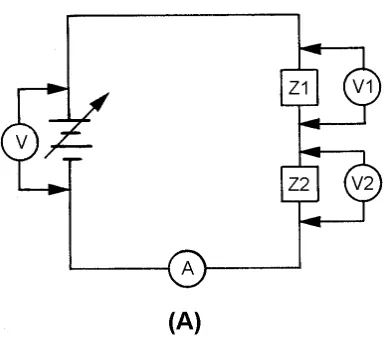
The series combination of a linear and a nonlinear impedance is illustrated in view (A) of figure 1-9. The voltage-current charts of Z1 and Z2 are shown in view (B). A chart of the combined impedance can be plotted by adding the amount of voltage required to produce a particular current through linear
impedance Z1 to the amount of voltage required to produce the same amount of current through nonlinear impedance Z2. The total will be the amount of voltage required to produce that particular current through the series combination. For example, point a (25 volts) is added to point c (50 volts) which yields point e
(75 volts); and point b (50 volts) is added to point d (100 volts) which yields point f (150 volts). Intermediate points may be determined in the same manner and the resultant characteristic curve (Z1 + Z2) is obtained for the series combination.
Figure 1-9A.—Combined linear and nonlinear impedances.
You should see from this graphic analysis that when a linear impedance is combined with a nonlinear impedance, the resulting characteristic curve is nonlinear. Some examples of nonlinear impedances are crystal diodes, transistors, iron-core transformers, and electron tubes.
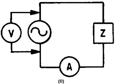
AC APPLIED TO LINEAR AND NONLINEAR IMPEDANCES
Figure 1-10 illustrates an ac sine-wave generator applied to a circuit containing several linear impedances. A sine-wave voltage applied to linear impedances will cause a sine wave of current through them. The wave shape across each linear impedance will be identical to the applied waveform.
Figure 1-10.—Sine wave generator applied to several impedances.
The amplitude, on the other hand, may differ from the amplitude of the applied voltage. Furthermore, the phase of the voltage developed by any of the impedances may not be identical to the phase of the voltage across any of the other impedances or the phase of the applied voltage. If an impedance is a reactive component (coil or capacitor), voltage or current may lead or lag, but the wave shape will remain the same. In a linear circuit, the output of the generator is not distorted. The frequency remains the same throughout the entire circuit and no new frequencies are generated.
Figure 1-11A.—Circuit with nonlinear impedances.
Figure 1-11B.—Circuit with nonlinear impedances.
Figure 1-12B.—Waveform in a circuit with nonlinear impedances.
The waveform in view (B) is no longer identical to that of view (A) and the nonlinear impedance network has generated HARMONIC FREQUENCIES. The waveform now consists of the fundamental frequency and its harmonics. (Harmonics were discussed in NEETS, Module 9, Introduction to
Wave-Generation and Wave-Shaping Circuits.)
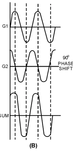
TWO SINE WAVE GENERATORS IN LINEAR CIRCUITS
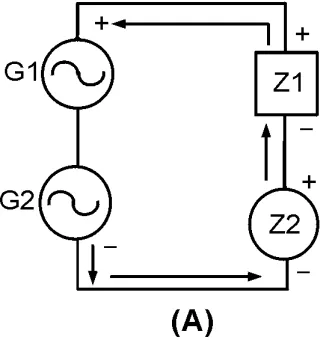
A circuit composed of two sine-wave generators, G1 and G2, and two linear impedances, Z1 and Z2, is shown in figure 1-13. The voltage applied to Z1 and Z2 will be the vector sum of the generator
voltages. The sum of the individual instantaneous voltages across each impedance will equal the applied voltages.
Figure 1-13.—Two sine-wave generators with linear impedances.
Figure 1-14A.—Waveforms across two nonlinear impedances.
Figure 1-14B.—Waveforms across two nonlinear impedances.
[image:33.612.241.368.381.644.2]time and compute the sine-wave voltage developed across each impedance for that generator input. Then, combine the instantaneous voltages (caused by each generator input) to obtain the complex waveform across each impedance. The nature of the impedance (resistive or reactive) will determine the shape of the complex waveform. Because the complex waveform is the sum of two individual sine waves, the
[image:34.612.232.379.150.321.2]composite waveform contains only the two original frequencies.
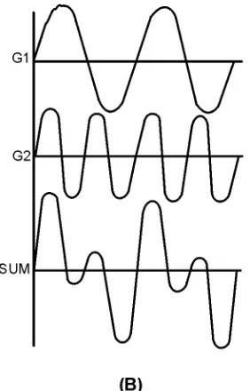
[image:34.612.237.378.357.577.2]Figure 1-15A.—Sine-wave generators with different frequencies and linear impedances.
Figure 1-15B.—Sine-wave generators with different frequencies and linear impedances.
Linear impedances may alter complex waveforms, but they do not produce new frequencies. The output of one generator does not influence the output of the other generator.
TWO SINE WAVE GENERATORS AND A COMBINATION OF LINEAR AND NONLINEAR IMPEDANCES
combined linear and nonlinear impedance circuit, the voltages developed across the impedances are complex waveforms.
Figure 1-16.—Sine-wave generators with a combination of impedances.
When two sine wave voltages are applied to a circuit, as in figure 1-16, nonlinear impedance Z2 reshapes the two sine-wave inputs and their harmonics, resulting in a very complex waveform.
Assume that nonlinear impedance Z2 will allow current to flow only when the sum of the two sine-wave generators (G1 and G2) has the polarity indicated. The waveforms present across the linear impedance will appear as a varying waveform. This will be a complex waveform consisting of:
•
a dc level•
the two fundamental sine wave frequencies•
the harmonics of the two fundamental frequencies•
the sum of the fundamental frequencies•
the difference between frequenciesThe sum and difference frequencies occur because the phase angles of the two fundamentals are constantly changing. If generator G1 produces a 10-hertz voltage and generator G2 produces an 11-hertz voltage, the waveforms produced because of the nonlinear impedance will be as shown in the following list:
•
a 10-hertz voltage•
an 11-hertz voltage•
harmonics of 10 hertz and 11 hertz (the higher the harmonic, the lower its strength)•
the sum of 10 hertz and 11 hertz (21 hertz)Figure 1-17 illustrates the relationship between the two frequencies (10 and 11 hertz). Since the waveforms are not of the same frequency, the 10 hertz of view (B) and the 11 hertz of view (A) will be in phase at some points and out of phase at other points. You can see this by closely observing the two waveforms at different instants of time. The result of the differences in phase of the two sine waves is shown in view (C). View (D) shows the waveform that results from the nonlinearity in the circuit.
Figure 1-17A.—Frequency relationships.
Figure 1-17B.—Frequency relationships.
Figure 1-17C.—Frequency relationships.
Figure 1-17D.—Frequency relationships.
The most important point to remember is that when varying voltages are applied to a circuit which contains a nonlinear impedance, the resultant waveform contains frequencies which are not present at the input source.
SPECTRUM ANALYSIS
The heterodyning process can be analyzed by using SPECTRUM ANALYSIS (the display of electromagnetic energy arranged according to wavelength or frequency). As shown in figure 1-18, spectrum analysis is an effective way of viewing the energy in electronic circuits. It clearly shows the relationships between the two fundamental frequencies (10 and 11 hertz) and their sum (21 hertz) and difference (1 hertz) frequencies. It also allows you to view the BANDWIDTH (the amount of the frequency spectrum that signals occupy) of the signal you are studying.
Figure 1-18.—Spectrum analysis of heterodyned signal. TYPICAL HETERODYNING CIRCUIT
Two conditions must be met in a circuit for heterodyning to occur. First, at least two different frequencies must be applied to the circuit. Second, these signals must be applied to a nonlinear impedance. These two conditions will result in new frequencies (sum and difference) being produced. Any one of the frequencies can be selected by placing a frequency-selective device (such as a tuned tank circuit) in series with the nonlinear impedance in the circuit.
Figure 1-19 illustrates a basic heterodyning circuit. The diode D1 serves as the nonlinear impedance in the circuit. Generators G1 and G2 are signal sources of different frequencies. The primary of T1, with its associated capacitance, serves as the frequency-selective device.
The principles of this circuit are similar to those of the block diagram circuit of figure 1-16. Notice in figure 1-19 that the two generators are connected in series. Therefore, the resultant waveform of their combined frequencies will determine when the cathode of D1 will be negative with respect to the anode, thereby controlling the conduction of the diode. The new frequencies that are generated by applying these signals to nonlinear impedance D1 are the sum and difference of the two original frequencies. The frequency-selective device T1 may be tuned to whichever frequency is desired for use in later circuit stages. Heterodyning action takes place, intentionally or not, whenever these conditions exist. Heterodyning (MIXING) circuits are found in most electronic transmitters and receivers. These transmitter and receiver circuits will be explained in detail later in this module.
Q-14. Define the heterodyne principle. Q-15. What is a nonlinear impedance? Q-16. What is spectrum analysis?
Q-17. What two conditions are necessary for heterodyning to take place?
AMPLITUDE-MODULATED SYSTEMS
Amplitude modulation refers to any method of varying the amplitude of an electromagnetic carrier frequency in accordance with the intelligence to be transmitted by the carrier. The CARRIER frequency is a radio-frequency wave suitable for modulation by the intelligence to be transmitted. One form of this method of modulation is simply to interrupt the carrier in accordance with a prearranged code.
CONTINUOUS WAVE (CW)
The "on-off" KEYING of a continuous wave (cw) carrier frequency was the principal method of modulating a carrier in the early days of electrical communications. The intervals of time when a carrier either was present or absent conveyed the desired intelligence. This is still used in modern
communications. When applied to a continuously oscillating radio-frequency source, on-off keying is referred to as cw signaling. This type of communication is sometimes referred to as an interrupted continuous wave (icw).
Development
The use of a cw transmitter can be very simple. All that is required for the transmitter to work properly is a device to generate the oscillations, a method of keying the oscillations on and off, and an antenna to radiate the energy. Continuous wave was the first type of modulation used. It is still
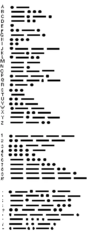
extensively used for long-range communications. When Marconi and others were attempting the transfer of intelligence between two points, without reliance on a conducting path, they employed the use of a practical coding system known as Morse code. You probably know that Morse code is a system of on-off keying developed for telegraph that is capable of passing intelligence over wire at an acceptable rate. Morse code consists only of periods of signal and no-signal.
during which signal is present is called the MARKING interval, and the period of no signal is called the SPACING interval. Figure 1-22 shows the relationships between the rf carrier view (A), the on-off keying waveform view (B), and the resultant carrier wave view (C).
Figure 1-20.—International Morse code.
Figure 1-22A.—Essential elements of ON-OFF keying.
Figure 1-22B.—Essential elements of ON-OFF keying.
Keying Methods
Keying a transmitter causes an rf signal to be radiated only when the key contacts are closed. When the key contacts are open, the transmitter does not radiate energy. Keying is accomplished in either the oscillator or amplifier stage of a transmitter. A number of different keying systems are used in Navy transmitters.
In most Navy transmitters, the hand telegraph key is at a low-voltage potential with respect to ground. A keying bar is usually grounded to protect the operator. Generally, a keying relay, with its contacts in the center-tap lead of the filament transformer, is used to key the equipment. Because one or more stages use the same filament transformer, these stages are also keyed. A class C final amplifier, when operated with fixed bias, is usually not keyed. This is because no output occurs when no excitation is applied in class C operation. Keying the final amplifier along with the other stages is not necessary in this case.
[image:41.612.170.440.366.705.2]OSCILLATOR KEYING.—Two methods of OSCILLATOR KEYING are shown in figure 1-23. In view (A) the grid circuit is closed at all times. The key (K) opens and closes the negative side of the plate circuit. This system is called PLATE KEYING. When the key is open, no plate current can flow and the circuit does not oscillate. In view (B), the cathode circuit is open when the key is open and neither grid current nor plate current can flow. Both circuits are closed when the key is closed. This system is called CATHODE KEYING. Although the circuits of figure 1-23 may be used to key amplifiers, other keying methods are generally employed because of the high values of plate current and voltage encountered.
Figure 1-23A.—Oscillator keying.
BLOCKED-GRID KEYING.—Two methods of BLOCKED-GRID KEYING are shown in figure 1-24. The key in view (A) shorts cathode resistor R1 allowing normal plate current to flow. With the key open, reduced plate current flows up through resistor R1 making the end connected to grid resistor Rg negative. If R1 has a high enough value, the bias developed is sufficient to cause cutoff of plate current. Depressing the key short-circuits R1. This increases the bias above cutoff and allows the normal flow of plate current. Grid resistor Rg is the usual grid-leak resistor for normal biasing.
[image:42.612.193.423.391.591.2]Figure 1-24A.—Blocked-grid keying.
Figure 1-24B.—Blocked-grid keying.
When greater frequency stability is required, the oscillator should not be keyed, but should remain in continuous operation; other transmitter circuits may be keyed. This procedure keeps the oscillator tube at a normal operating temperature and offers less chance for frequency variations to occur each time the key is closed.
KEYING RELAYS.—In transmitters using a crystal-controlled oscillator, the keying is almost always in a circuit stage following the oscillator. In large transmitters (75 watts or higher), the ordinary hand key cannot accommodate the plate current without excessive arcing.
WARNING
BECAUSE OF THE HIGH PLATE POTENTIALS USED, OPERATING A HAND KEY IN THE PLATE CIRCUIT IS DANGEROUS. A SLIGHT SLIP OF THE HAND BELOW THE KEY KNOB COULD RESULT IN SEVERE SHOCK OR, IN THE CASE OF DEFECTIVE RF PLATE CHOKES, A SEVERE RF BURN.
In larger transmitters, some local low-voltage supply, such as a battery, is used with the hand key to open and close a circuit through the coils of a KEYING RELAY. The relay contacts open and close the keying circuit of the amplifier. A schematic diagram of a typical relay-operated keying system is shown in figure 1-25. The hand key closes the circuit from the low-voltage supply through the coil (L) of the keying relay. The relay armature closes the relay contacts as a result of the magnetic pull exerted on the armature. The armature moves against the tension of a spring. When the hand key is opened, the relay coil is deenergized and the spring opens the relay contacts.
Figure 1-25.—Relay-operated keying system.
Figure 1-26A.—Key-click filters.
Figure 1-26B.—Key-click filters.
The capacitors and rf chokes in figure 1-26, views (A) and (B), prevent surges of current. In view (B), the choke coil causes a lag in the current when the key is closed, and the current builds up gradually instead of instantly. The capacitor charges as the key is opened and slowly releases the energy stored in the magnetic field of the inductor. The resistor controls the rate of charge of the capacitor and also prevents sparking at the key contacts by the sudden discharge of the capacitor when the key is closed.
MACHINE KEYING.—The speed with which information can be transmitted using a hand key depends on the keying ability of the operator. Early communicators turned to mechanized methods of keying the transmitters to speed transmissions. More information could be passed in a given time by replacing the hand-operated key with a keying device capable of reading information from punched tape. Using this method, several operators could prepare tapes at their normal operating speed. The tapes could then be read through the keying device at a higher rate of speed and more information could be
transmitted in a given amount of time.
Spectrum Analysis
analysis (figure 1-27) illustrates the transmitted frequency characteristics of a cw signal. Because the cw signal is a pure sine wave, it occupies only a single frequency in the rf spectrum and the system is relatively simple.
Figure 1-27.—Carrier-wave signal spectrum analysis.
Q-18. What is amplitude modulation?
Q-19. What are the three requirements for cw transmission? Q-20. Name two methods of oscillator keying.
Q-21. State the method used to increase the speed of keying in a cw transmitter. Q-22. Name three advantages of cw transmission.
Single-Stage Transmitters
[image:45.612.221.387.123.252.2]A simple, single-tube cw transmitter can be made by coupling the output of an oscillator directly to an antenna (figure 1-28). The primary purpose of the oscillator is to develop an rf voltage which has a constant frequency and is immune to outside factors which may cause its frequency to shift. The output of this simple transmitter is controlled by placing a telegraph key at point K in series with the voltage supply. Since the plate supply is interrupted when the key is open, the circuit oscillates only as long as the key is closed. Although the transmitter shown uses a Colpitts oscillator, any of the oscillators previously described in NEETS, Module 9, Introduction to Wave-Generation and Wave-Shaping Circuits can be used.
Capacitors C2 and C3 can be GANGED (mechanically linked together) to simplify tuning. Capacitor C1 is used to tune (resonate) the antenna to the transmitter frequency. CA is the effective capacitance existing between the antenna and ground. This antenna-to-ground capacitance is in parallel with the tuning capacitors, C2 and C3. Since the antenna has capacitance, any change in its length or position, such as that caused by swaying of the antenna, changes the value of CA and causes the oscillator to change frequency. Because these frequency changes are undesirable for reliable communications, the multistage transmitter was developed to increase reliability.
Multistage Transmitters
The simple, single-tube transmitter, shown in figure 1-28, is rarely used in practical equipment. Most of the transmitters you will see use a number of tubes or stages. The number used depends on the
frequency, power, and application of the equipment. For your study, the following three categories of cw transmitters are discussed: (1) master oscillator power amplifier (mopa) transmitters, (2) multistage, high-power transmitters, (3) high- and very-high frequency transmitters.
The mopa is both an oscillator and a power amplifier. Power-amplifying stages and frequency-multiplying stages must be used to increase power and raise the frequency from those achievable in a mopa. The main difference between many low- and high-power transmitters is in the number of power-amplifying stages that are used. Similarly, the main difference between many high- and very-high frequency transmitters is in the number of frequency-multiplying stages used.
MASTER OSCILLATOR POWER AMPLIFIER.—For a transmitter to be stable, its oscillator must not be LOADED DOWN. This means that its antenna (which can present a varying impedance) must not be connected directly to the oscillator circuit. The rf oscillations must be sent through another circuit before they are fed to the antenna for good frequency stability to be obtained. That additional circuit is an rf power amplifier. Its purpose is to raise the amplitude of rf oscillations to the required output power level and isolate the oscillator from the antenna. Any transmitter consisting of an oscillator and a single-amplifier stage is called a master oscillator power amplifier transmitter (mopa), as shown in figure 1-29.
Figure 1-29.—Block diagram of a master oscillator power amplifier transmitter (mopa).
Most mopa transmitters have only one tube amplifier in the power-amplifier stage. However, the oscillator may not produce sufficient power to drive a power-amplifier tube to the power output level required for the antenna. In such cases, the power-amplifier stages are designed to use two or more amplifiers which can be driven by the oscillator. Two or more amplifiers can be connected in parallel (with similar elements of each tube connected) or in a push-pull arrangement. In a push-pull amplifier, the grids are fed equal rf voltages that are 180 degrees out of phase.
frequency. A second advantage is that the rf power amplifier is operated so that a small change in the voltage applied to its grid circuit will produce a large change in the power developed in its plate circuit.
Rf power amplifiers require that a specific amount of power be fed into the grid circuit. Only in this way can the tube deliver an amplified power output. However, the stable oscillator can produce only limited amounts of power. Therefore, the mopa transmitter is limited in the amount of power it can develop. This is one of the disadvantages of the mopa transmitter. Another disadvantage is that it often is impractical for use at very- and ultra-high frequencies. The reason is that the stability of self-excited oscillators decreases rapidly as the operating frequency increases. Circuit tuning capacitances are small at high frequencies and stray capacitances adversely affect frequency stability.
MULTISTAGE HIGH-POWER TRANSMITTERS.—The power amplifier of a high-power transmitter may require far more driving power than can be supplied by an oscillator. Therefore, one or more low-power intermediate amplifiers may be inserted between the oscillator and the final power amplifier to boost power to the antenna. In some types of equipment, a VOLTAGE AMPLIFIER, called a BUFFER is used between the oscillator and the first intermediate amplifier. The ideal buffer is operated class A and is biased negatively to prevent grid current flow during the excitation cycle. Therefore, it does not require driving power from, nor does it load down, the oscillator. The purpose of the buffer is to isolate the oscillator from the following stages and to minimize changes in oscillator frequency that occur with changes in loading. A buffer is required when keying takes place in an intermediate or final amplifier operating at comparatively high power. Look at the block diagrams of several medium-frequency
[image:47.612.88.534.392.692.2]transmitters in figure 1-30. The input and output powers are given for each stage. You should be able to see that the power output rating of a transmitter can be increased by adding amplifier tubes capable of delivering the power required.
HF AND VHF TRANSMITTERS.—Oscillators are too unstable for direct frequency control in very- and ultra-high frequency transmitters. Therefore, these transmitters have oscillators operating at comparatively low frequencies, sometimes as low as 1/100 of the output frequency. The oscillator frequency is raised to the required output frequency by passing it through one or more FREQUENCY MULTIPLIERS. Frequency multipliers are special rf power amplifiers which multiply the input frequency. In practice, the MULTIPLICATION FACTOR (number of times the input frequency is multiplied) is seldom larger than five in any one stage. The block diagram of a typical VHF transmitter, designed for continuous tuning between 256 and 288 megahertz, is shown in figure 1-31.
Figure 1-31.—Block diagram of a vhf transmitter.
The stages which multiply the frequency by two are DOUBLERS; those which multiply by four are QUADRUPLERS. The oscillator is tunable from 4 to 4.5 megahertz. The multiplier stages increase the frequency by multiplying successively by 4, 4, 2, and 2, for a total factor of 64. In power, high-frequency transmitters, one or more intermediate amplifiers may be used between the last high-frequency multiplier and the power amplifier.
Q-23. Name a disadvantage of a single-stage cw transmitter.
Q-24. What is the purpose of the power-amplifier stage in a master oscillator power amplifier cw transmitter?
Q-25. What is the purpose of frequency-multiplier stages in a VHF transmitter?
AMPLITUDE MODULATION
The telegraph and radiotelegraph improved man's ability to communicate by allowing speedy passage of information between two distant points. However, it failed to satisfy one of man's other communications needs; that is, the ability to hear and be heard, by voice, at a great distance. In an effort to improve on the telegraph, Alexander Graham Bell developed the principles on which modern
Microphones
If an rf carrier is to convey intelligence, some feature of the carrier must be varied in accordance with the information to be transmitted. In the case of speech intelligence, sound waves must be converted to electrical energy.
A MICROPHONE is an energy converter that changes sound energy into electrical energy. A diaphragm in the microphone moves in and out in accordance with the compression and rarefaction of the atmosphere caused by sound waves. The diaphragm is connected to a device that causes current flow in proportion to the instantaneous pressure delivered to it. Many devices can perform this function. The particular device used in a given application depends on the characteristics desired, such as sensitivity, frequency response, impedance matching, power requirements, and ruggedness.
The SENSITIVITY or EFFICIENCY of a microphone is usually expressed in terms of the electrical power level which the microphone delivers to a matched-impedance load compared to the sound level being converted. The sensitivity is rated in dB and must be as high as possible. A high microphone output requires less gain in the amplifiers used with the microphone. This keeps the effects of thermal noise, amplifier hum, and noise pickup at a minimum.
For good quality sound reproduction, the electrical signal from the microphone must correspond in frequency content to the original sound waves. The microphone response should be uniform, or flat, within its frequency range and free from the electrical or mechanical generation of new frequencies.
The impedance of a microphone is important in that it must be matched to the microphone cable and to the amplifier input as well as to the amplifier input load. Exact impedance matching is not always possible, especially in the case where the impedance of the microphone increases with an increase in frequency. A long microphone cable tends to seriously attenuate the high frequencies if the microphone impedance is high. This attenuation is caused by the increased capacitive action of the line at higher frequencies. If the microphone has a low impedance, a lower voltage is developed in the microphone, and more voltage is available at the load. Because many microphone lines used aboard ship are long, low-impedance microphones must be used to preserve a sufficiently high voltage level- over the required frequency range.
[image:49.612.222.395.514.616.2]The symbol used to represent a microphone in a schematic diagram is shown in figure 1-32. The schematic symbol identifies neither the type of microphone used nor its characteristics.
Figure 1-32.—Microphone schematic symbol.
primary of a transformer. The changing resistance of the carbon pile produces a corresponding change in the current of the circuit. The varying current in the transformer primary produces an alternating voltage in the secondary. The transformer steps up the voltage and matches the low impedance of the microphone to the high impedance of the first amplifier. The voltage across the secondary may be as high as 25 volts peak. The impedance of this type of microphone varies from 50 to 200 ohms. This effect is caused by the pressure of compression and rarefaction of sound waves, discussed in chapter 1 of NEETS, Module 10, Introduction to Wave Propagation, Transmission Lines, and Antennas.
Figure 1-33A.—Carbon microphones. SINGLE-BUTTON CARBON MICROPHONE.
[image:50.612.182.433.177.400.2]The DOUBLE-BUTTON CARBON MICROPHONE is shown in figure 1-33, view (B). Here, one button is positioned on each side of the diaphragm so that an increase in resistance on one side is accompanied by a simultaneous decrease in resistance on the other. Each button is in series with the battery and one-half of the transformer primary. The decreasing current in one-half of the primary and the increasing current in the other half produces an output voltage in the secondary winding. The output voltage is proportional to the sum of the primary winding signal components. This action is similar to that of push-pull amplifiers.
One disadvantage of carbon microphones is that of a constant BACKGROUND HISS (hissing noise) which results from random changes in the resistance between individual carbon granules. Other
disadvantages are reduced sensitivity and distortion that may result from the granules packing or sticking together. The carbon microphone also has a limited frequency response. Still another disadvantage is a requirement for an external voltage source.
The disadvantages, however, are offset by advantages that make its use in military applications widespread. It is lightweight, rugged, and can produce an extremely high output.
CRYSTAL MICROPHONE.—The CRYSTAL MICROPHONE uses the PIEZOELECTRIC EFFECT of Rochelle salt, quartz, or other crystalline materials. This means that when mechanical stress is placed upon the material, a voltage electromagnetic force (EMF) is generated. Since Rochelle salt has the largest voltage output for a given mechanical stress, it is the most commonly used crystal in microphones. View (A) of figure 1-34 is a crystal microphone in which the crystal is mounted so that the sound waves strike it directly. View (B) has a diaphragm that is mechanically linked to the crystal so that the sound waves are indirectly coupled to the crystal.
Figure 1-34A.—Crystal microphones.
A crystal microphone has a high impedance and does not require an external voltage source. It can be connected directly into the input circuit of a high-gain amplifier. However, because its output is low, several stages of high-gain amplification are required. Crystal microphones are delicate and must be handled with care. Exposure to temperatures above 52 degrees Celsius (125 degrees Fahrenheit) may permanently damage the crystal unit. Crystals are also soluble in water and other liquids and must be protected from moisture and excessive humidity.
DYNAMIC MICROPHONE.—A cross section of the DYNAMIC or MOVING-COIL
MICROPHONE is shown in figure 1-35. A coil of fine wire is mounted on the back of the diaphragm and located in the magnetic field of a permanent magnet. When sound waves strike the diaphragm, the coil moves back and forth cutting the magnetic lines of force. This induces a voltage into the coil that is an electrical reproduction of the sound waves.
Figure 1-35.—Dynamic microphone.
The sensitivity of the dynamic microphone is almost as high as that of the carbon type. It is lightweight and requires no external voltage. The dynamic microphone is rugged and can withstand the effects of vibration, temperature, and moisture. This microphone has a uniform response over a frequency range that extends from 40 to 15,000 hertz. The impedance is very low (generally 50 ohms or less). A transformer is required to match its impedance to that of the input of an af amplifier.
Figure 1-36.—Magnetic microphone action.
When the armature is in its resting position (midway between the two poles), the magnetic flux is established across the air gap. However, no resultant flux is established in the armature. When a
compression wave strikes the diaphragm, the armature is deflected to the right. Most of the flux continues to move in the direction of the arrows. However, some flux now flows from the north pole of the magnet across the reduced gap at the upper right, down through the armature, and around to the south pole of the magnet.
When a rarefaction wave occurs at the diaphragm, the armature is deflected to the left. Some flux is now directed from the north pole of the magnet, up through the armature, through the reduced gap at the upper left, and back to the south pole.
The vibrations of the diaphragm cause an alternating flux in the armature which induces an
alternating voltage in the coil. This voltage has the same waveform as that of the sound waves striking the diaphragm.
The magnetic microphone is very similar to the dynamic microphone in terms of impedance, sensitivity, and frequency response. However, it is more resistant to vibration, shock, and rough handling than other types of microphones.
Changing sound waves into electrical impulses is the first step in voice communications. It is
common to all the transmission media you will study in the remainder of this chapter. We will discuss the various types of modulation that arc used to transfer this information to a transmission medium in the following sections.
Q-26. What is a microphone?
Q-27. What special electromechanical effect is the basis for carbon microphone operation? Q-28. What is a major disadvantage of a carbon microphone?
Q-29. What property of a crystalline material is used in a crystal microphone?
AM TRANSMITTER PRINCIPLES
In this section we will describe the methods used to apply voice signals (intelligence) to a carrier wave by the process of amplitude modulation (AM).
An AM transmitter can be divided into two major sections according to the frequencies at which they operate, radio-frequency (rf) and audio-frequency (af) units. The rf unit is the section of the transmitter used to generate the rf carrier wave. As illustrated in figure 1-37, the carrier originates in the master oscillator stage where it is generated as a constant-amplitude, constant-frequency sine wave. The carrier is not of sufficient amplitude and must be amplified in one or more stages before it attains the high power required by the antenna. With the exception of the last stage, the amplifiers between the oscillator and the antenna are called INTERMEDIATE POWER AMPLIFIERS (ipa). The final stage, which connects to the antenna, is called the FINAL POWER AMPLIFIER (fpa).
Figure 1-37.—Block diagram of an AM transmitter.
The second section of the transmitter contains the audio circuitry. This section of the transmitter takes the small signal from the microphone and increases its amplitude to the amount necessary to fully modulate the carrier. The last audio stage is the MODULATOR. It applies its signal to the carrier in the final power amplifier. In this way, intelligence is included in the radiated rf waveform.
The Modulated Wave
Figure 1-38.—Radio-frequency spectrum.
Radiating energy at audio frequencies (discussed earlier in this chapter) is not practical. The heterodyning principle, however, makes possible the conversion of an af signal (intelligence) to an rf signal (with af intelligence) which can be radiated or transmitted through space.
Look again at figure 1-38. The sum and difference frequencies are located very near the rf signal (100 kilohertz), while the audio signal (5 kilohertz) is spaced a considerable distance away. Because of this frequency separation, the audio frequency can be easily removed by filter circuits, leaving just three radio frequencies of 95, 100, and 105 kilohertz. These three radio frequencies are radiated through space to the receiving station. At the receiver, the process is reversed. The frequency of 95 kilohertz, for example, is heterodyned with the frequency of 100 kilohertz and the sum and difference frequencies are again produced. (A similar process occurs between the frequencies of 100 and 105 kilohertz.) Of the resultant frequencies (95, 100, 105, and 5 kilohertz), all are filtered out except the 5 kilohertz difference frequency. This frequency, which is identical to the original 5 kilohertz audio applied at the transmitter, is retained and amplified. Thus, the 5 kilohertz audio tone appears to have been radiated