Performance analysis of the Linux firewall in a host
A Thesis
Presented to the Faculty of California Polytechnic State University
San Luis Obispo
In Partial Fulfillment
Of the Requirements for the Degree Master of Science in Electrical Engineering
By
Authorization for Reproduction of Master’s Thesis
I hereby grant permission for the reproduction of this thesis, in whole or in part, without further authorization from me.
Signature (Américo J. Melara)
Approval Page
Title: Performance analysis of the Linux firewall in a host
Author: Américo J. Melara
Date Submitted: June 12, 2002
Dr. James Harris
Advisor Signature
Dr. Hugh Smith
Committee Member Signature
Dr. Phillip Nico
Committee Member Signature
Dr. Fred DePiero
Abstract
Performance analysis of the Linux firewall in a host
Firewalls are one of the most commonly used security systems to protect networks and hosts. Most researchers have focused on analyzing the latency and throughput of router firewalls. Different from this approach, this research focuses on studying the performance impact and the sensitivity of the Linux firewall (iptables) for a single host.
In order to be able to measure the performance and the sensitivity of the firewall, we designed and instrumented each layer of the Linux TCP/IP stack. This instrumentation was used to test the host’s firewall under two scenarios: In the first scenario, we captured the path and the latency of one single packet; in the second scenario, we captured the latency of multiple packets sent to the host at various transmission rates.
Our measurement results indicate that the firewall is sensitive to the number of rules, the type of filtering, and the transmission rate. The results of our first scenario demonstrate that for each type of filtering, latency increases linearly as the number of rules increase. Furthermore, the second test scenario shows that latency decreases as the packet transmission rate increases.
Acknowledgments
Tables of Contents
CHAPTER 1 INTRODUCTION...1
CHAPTER 2 OVERVIEW OF SECURITY...4
2.1 NETWORK VULNERABILITIES – AN OSI PERSPECTIVE... 4
2.1.1 Operating Systems attacks ... 8
2.1.2 Denial of Service Attacks ... 11
2.2 NETWORK PROTECTION TECHNIQUES... 12
2.2.1 Authentication and Encryption ... 12
2.2.2 Intrusion Detection ... 14
2.2.3 Firewalls ... 15
CHAPTER 3 FIREWALL PERFORMANCE STUDY ... 19
3.1 PREVIOUS RESEARCH... 20
3.1.1 Analyzing and Testing Firewall Policies ... 20
3.1.2 Testing the Performance of the Firewall ... 21
3.2 TERMINOLOGY... 24
3.2.1 Performance Metrics ... 24
3.2.2 Parameters to determine the firewall sensitivity ... 27
3.3 TESTS DEFINITIONS... 28
3.3.1 Single-packet tests... 29
3.3.2 Throughput tests... 30
3.3.3 Packet specifications... 32
3.4 THE LINUX TCP/IP STACK... 32
3.4.1 Understanding the packet data flow ... 32
3.5 SOFTWARE INSTRUMENTATION... 39
3.5.1 Software design and issues ... 39
3.5.2 Instrumentation of the Timestamps... 41
3.6 THE LINUX FIREWALL – IPTABLES ... 49
3.6.1 Iptables Application ... 49
3.6.2 Architecture of the Netfilter ... 52
3.6.3 Netfilter Base ... 53
CHAPTER 4 FIREWALL PERFORMANCE RESULTS... 58
4.1 BACK-TO-BACK TIMING FOR THE SINGLE-PACKET TESTS INSTRUMENTATION 58 4.2 PROCEDURES FOR SINGLE-PACKET TESTS... 61
4.3 SINGLE-PACKET TEST RESULTS... 62
4.3.1 Timing the network stack ... 62
4.3.2 T2 – T1 ... 63
4.3.3 T4 – T3 ... 64
4.3.4 T5 – T4 ... 64
4.4 INPUT POLICY ACCEPT VS. DROP ... 65
4.5 TCP AND UDP FIREWALL PERFORMANCE [T3 – T2] ... 66
4.5.1 Payload size effect... 67
4.5.2 Number of rules effect... 69
4.5.3 Linear relationship of [T3 – T2] ... 70
4.6 TOTAL PROCESSING TIME [T5 – T1] WITH RESPECT TO [T3 – T2]... 72
4.6.1 Firewall % overhead with respect to T5 – T1... 72
4.7 LATENCY RESULTS FOR VARIOUS THROUGHPUTS... 74
4.7.1 Test procedures... 74
4.7.2 Back-to-back timing measurements for throughput tests... 75
4.7.3 Test results ... 76
CHAPTER 5 CONCLUSION AND FUTURE WORK ... 79
5.1 SUMMARY... 79
5.2 POSSIBLE FUTURE WORK... 80
BIBLIOGRAPHY ... 82
APPENDIX A PERFORMING TESTS IN THE CO-HOST ... 86
A.1 HARDWARE... 86
A.2 SOFTWARE IN THE CO-HOST... 87
A.3 TIMESTAMP IMPLEMENTATION ON THE EBSA21285 ... 88
A.3.1 Clocks... 88
A.3.2 Timers ... 88
A.3.3 Controlling the time registers ... 90
APPENDIX B SETUP FOR TESTING A FIREWALL FOR A SINGLE HOST... 93
B.1 SINGLE PACKET TESTS... 93
B.2 MULTIPLE PACKETS... 98
List of Figures
FIGURE 2-1 RELATIONSHIP BETWEEN THE TCP/IP REFERENCE MODEL AND VARIOUS
OPERATING SYSTEM AND USER LEVEL SECURITY SERVICES... 6
FIGURE 2-2 ACQUIRING THE SERVER’S OPERATING SYSTEM TYPE AND VERSION THROUGH A TELNET SESSION... 7
FIGURE 2-3 AUTHENTICATION PROCESS TO ESTABLISH AN ENCRYPTED COMMUNICATION BETWEEN A CLIENT AND A SERVER USING KERBEROS... 13
FIGURE 2-4 A SINGLE-HOST FIREWALL PROTECTS ONLY ONE COMPUTER... 16
FIGURE 2-5 EXAMPLE OF A ROUTER FIREWALL PROTECTING MULTIPLE COMPUTERS INSIDE A NETWORK... 17
FIGURE 3-1 EXAMPLE OF A PACKET IN ORDER TO MEASURE ITS LATENCY TO TRAVERSE THE STACK... 25
FIGURE 3-2 PARAMETERS TO DETERMINE THE SENSITIVITY OF THE FIREWALL... 27
FIGURE 3-3 TEST SETUP TO MEASURE THE LATENCY WHEN A SINGLE PACKET IS SENT EVERY 4 SECONDS... 30
FIGURE 3-4 TEST SETUP USING THE SPIRENT’S NETWORK TESTER TO VARY THE THROUGHPUT... 31
FIGURE 3-5 BASIC TCP CLIENT-SERVER CONNECTION... 34
FIGURE 3-6 RECEIVING OPERATION FROM APPLICATION TO SOCKET LAYER... 35
FIGURE 3-7 TRAVERSING THE NETWORK STACK – FROM BOTTOM UP... 38
FIGURE 3-8 TIMESTAMP HACK FOR THE DEVICE DRIVER (TIMESTAMP 1) ... 42
FIGURE 3-9 IP LAYER – BEGINNING OF THE FIREWALL (TIMESTAMP 2)... 44
FIGURE 3-10 IP LAYER – END OF THE FIREWALL (TIMESTAMP 3) ... 45
FIGURE 3-11 TCP LAYER – TIMING THE END OF THE TCP/IP STACK... 46
FIGURE 3-12 UDP LAYER – TIMESTAMP 4... 47
FIGURE 3-13 SOCKET LAYER – BEFORE DATA IS SENT TO THE APPLICATION (TIMESTAMP 5) ... 48
FIGURE 3-14 IPTABLES CONFIGURATION PROCESS... 50
FIGURE 3-15 PACKET TRAVERSES THE NETFILTER... 52
FIGURE 3-16 IPTABLES ALGORITHM – IPT_DO_TABLE( ) CHECKS FOR MATCHES IN THE RULE-SET... 55
FIGURE 3-17 IP_PACKET_MATCH FUNCTION–IP ADDRESS ARE ALWAYS CHECKED REGARDLESS OF THE TYPE OF FILTERING IN THE RULE-SET... 56
FIGURE 4-1 LATENCY INCREASES AS THE PAYLOAD SIZE INCREASES... 62
FIGURE 4-2 RANDOMNESS AT THE SOCKET LAYER –SOCKET LAYER IS CALLED RANDOMLY REGARDLESS OF THE NUMBER OF RULES... 65
FIGURE 4-3 TCP CONNECTION – [T3 – T2] – LINEAR RELATIONSHIP BETWEEN THE NUMBER OF RULES AND THE TIME TO PROCESS THE FIREWALL... 71
FIGURE 4-4 UDP CONNECTION – [T3 – T2] - LINEAR RELATIONSHIP BETWEEN THE NUMBER OF RULES AND THE TIME TO PROCESS THE FIREWALL... 71
FIGURE 4-5 COMPARISON BETWEEN T5-T1 FOR DIFFERENT TRANSMISSION RATES – LATENCY DECREASES AS THE THROUGHPUT INCREASES... 77
FIGURE A-2 CINIC ARCHITECTURE [22]... 87
FIGURE A-3 EBSA-21285 TIMER BLOCK DIAGRAM... 89
FIGURE A-4 ARM LINUX USE TO CONTROL OF TIMERS... 90
FIGURE A-5 USING TIMER CONTROL REGISTERS IN THE EBSA285 ... 91
List of Tables
TABLE 4-1 PACKET’S LATENCY (INCLUDING THE INSTRUMENTATION OVERHEAD) AS IT TRAVELS THE TCP/IP STACK... 59 TABLE 4-2 OVERHEAD OF THE SINGLE-PACKET TESTS INSTRUMENTATION... 59
TABLE 4-3 PACKET’S LATENCY (EXCLUDING THE INSTRUMENTATION OVERHEAD) AS IT TRAVELS THE TCP/IP STACK... 60 TABLE 4-4 PARAMETERS UNDER TEST... 61
TABLE 4-5 PAYLOAD IMPACT IN T2-T1 – TIME INCREASES AS THE PAYLOAD SIZE INCREASES... 63 TABLE 4-6 IMPACT OF THE PAYLOAD SIZE IN T4 – T3 – TIME INCREASES AS THE
PAYLOAD SIZE INCREASES... 64
TABLE 4-7 DIFFERENCE BETWEEN INPUT POLICY ACCEPT AND DROP –
FIREWALL IS NOT SENSITIVE TO THE INPUT POLICY... 66
TABLE 4-8 IP MATCHING FOR TCP AND UDP PACKETS – FIREWALL IS NOT
SENSITIVE TO THE PAYLOAD SIZE... 67 TABLE 4-9 MAC MATCHING FOR TCP AND UDP PACKETS – FIREWALL IS NOT
SENSITIVE TO THE PAYLOAD SIZE... 68
TABLE 4-10 TCP/UDP PORTS MATCHING FOR TCP AND UDP PACKETS – FIREWALL IS NOT SENSITIVE TO THE PAYLOAD SIZE... 68 TABLE 4-11 MATCHING IP – TIME INCREASES AS THE RULES INCREASE... 69
TABLE 4-12 MATCHING MAC ADDRESSES – TIME INCREASES AS RULES INCREASE 70
TABLE 4-13 MATCHING TCP PORTS – TIME INCREASES AS THE RULES INCREASE... 70 TABLE 4-14 TCP AND UDP TOTAL PROCESSING TIME [T5 – T1]... 72
TABLE 4-15 PERCENTAGE OVERHEAD OF IP MATCHING OVER THE T5 – T1 –
OVERHEAD INCREASES AS THE NUMBER OF RULES INCREASE... 73 TABLE 4-16 PERCENTAGE OVERHEAD OF MAC MATCHING OVER THE T5 – T1 -
OVERHEAD INCREASES AS THE NUMBER OF RULES INCREASE... 73
TABLE 4-17 PERCENTAGE OVERHEAD OF TCP MATCHING OVER T5 – T1 -
OVERHEAD INCREASES AS THE NUMBER OF RULES INCREASE... 74 TABLE 4-18 PARAMETERS UNDER TEST... 74
TABLE 4-19 INSTRUMENTATION OVERHEAD... 75
TABLE 4-20 DIFFERENCE IN THE LATENCY FOR VARIOUS THROUGHPUT – LATENCY DECREASES AS THE THROUGHPUT INCREASES... 76
Chapter 1
Introduction
Network Security is one of the most important fields dealing with the Internet. The ability to access and transfer information in a few seconds allows the government, companies, educational institutions, and individuals to accelerate the decision process or simply be “informed.” However, information can be very valuable and there is a need for better and faster security systems to protect information and networks.
Attacks are prevalent on the Internet, and for that reason Firewalls, Intrusion Detection Systems, Virus Scanners, File Protection and Integrity checks software, Buffer overflow protection techniques, and Encryption tools have been developed as security services to protect systems and information. The CiNIC is an independent network device designed to control all of the networking services for the host. Thereby, it can serve as the front line defense mechanism against attacks. The vision for it is to run security services such as the firewall, encryption, authentication, intrusion detection, and other services to secure the host.
performance on single hosts, we found that very little research had been done on the topic. In our end-of-the-year meeting with 3Com in December 2001, we were told that a third party vendor discovered that the firewall would degrade the performance of a system tremendously after 30 rules. In view of the lack of research and the uncertainty on what the firewall performance cost might be, we decided to study the performance of the Linux firewall iptables. This thesis presents a study of the
sensitivity and the performance impact produced by the Linux firewall iptables in a host.
We decided to test the performance of the firewall under two scenarios changing various parameters. The first scenario included tracing one single packet in order to measure the sensitivity of the firewall to:
(1) The INPUT policy (2) The number of rules (3) The type of filtering (4) The payload size
(5) The transmission protocol.
Chapter 2
Overview of Security
For individuals and enterprises the main purpose of security on a network system is the protection of information. We all use a network system one way or the other, either for sending e-mails, reading the news, making traveling plans, or shopping. In most of our transactions we wish to have one thing – protection of our information. But, what type of protection? Protection from whom? For large firms security includes not only the protection of the company’s information from outsiders but also the protection of their entire internal network. For example, top executives do not want their competitors to know their marketing or acquisitions strategies. Nor does a manager want intruders to read, delete, or acquire budgeting information or consumer’s information. Thus, the goal of security is to protect information and systems from “malicious intruders.”
This chapter’s intent is to organize and summarize the area of Security, and explain firewalls in more detail. The chapter is laid out as follows: First, the most relevant vulnerabilities for a host are explained briefly. Following, some of the techniques and tools used to prevent and detect attacks are presented. Finally, the idea of porting a firewall to the CiNIC architecture is presented.
2.1 Network Vulnerabilities – an OSI perspective
not make it immune or does not take away the chance of getting a virus, a Trojan horse, or just “get hacked.” So, the more knowledgeable the reader is about how someone can break into his system, the more cautious he will be, and the harder it will be to break in.
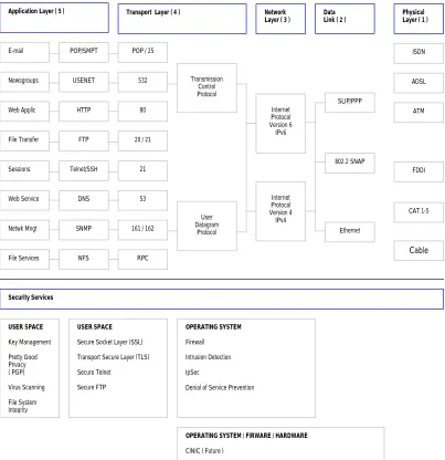
Figure 2-1 shows the end system’s TCP/IP stack model and some of the tools created to provide security for each layer. The figure can be explained as follows. Secure services are available at the Operating System level (OS) and at User space level. The transport layer is the point where the OS and user space separate. At the OS level we have a firewall (e.g. iptables), intrusion detection systems (e.g. Linux
Intrusion Detection System a.k.a. LIDS), IP Security or IpSec, and Denial of Service prevention. One of the goals of the CiNIC project is to offload these security services from the host to the co-host. For that reason, this research will focus on the firewall for the Linux Operating System.
Figure 2-1 Relationship between the TCP/IP Reference Model and various Operating System and User level Security Services
A security issue implied in the network stack is that a weakness or “hole” in one layer could lead to the exploitation of a lower layer, and vice-versa. For example,
through a simple telnet session anyone can find out the type of operating system
running on a particular machine. In Figure 2-2 the host fornax has requested a telnet Application Layer ( 5 ) Transport Layer ( 4 ) Network
Layer ( 3 ) Data Link ( 2 ) Physical Layer ( 1 )
E-mail Newsgroups Web Applic File Transfer Sessions Web Service Netwk Mngt File Services POP/SMPT USENET HTTP FTP Telnet/SSH DNS SNMP NFS
POP / 25
532
80
20 / 21
21
53
161 / 162
RPC Transmission Control Protocol SLIP/PPP 802.2 SNAP Ethernet ISDN ADSL ATM FDDI CAT 1-5 Cable Security Services User Datagram Protocol USER SPACE Key Management Pretty Good Privacy ( PGP) Virus Scanning File System Integrity OPERATING SYSTEM Firewall Intrusion Detection IpSec
Denial of Service Prevention
USER SPACE
Secure Socket Layer (SSL) Transport Secure Layer (TLS) Secure Telnet
Secure FTP
OPERATING SYSTEM / FIRWARE / HARDWARE
CiNIC ( Future )
session with the host orion. When the session starts, we observe that the host orion is
running Red- Hat Linux 7.1 with a kernel version 2.4.2-2. This may lead the attacker to look for software tools designed to attack the specific vulnerabilities found in the kernel 2.4.2-2.
Figure 2-2 Acquiring the server’s Operating System type and version through a Telnet Session
On their search for vulnerable systems, attackers use a technique called
footprinting. Footprinting is defined as the fine art of gathering information! [5] Information can be gathered through scanning or enumeration. Scanning is a tool used to find open ports and services running on a system, enumeration is the “ability to extract valid accounts or exported resource names from systems [5].” Some of the information to be gathered include Domain Names, specific IP addresses of systems reachable through the Internet, TCP and UDP services running on each system, system architecture, routing tables, access control mechanisms, related access control lists, etc. The list of tools available to extract this type of information is large, but some of the most common ones are nmap, the ping of death, tcpdump,
The network protocol by nature has its pitfalls. For example, an ICMP (Internet Control Message Protocol) packet, which is normally used to communicate control messages on the Internet between hosts and routers, contains diagnostics about your system. For example, a ping contains error detection information (e.g. network/host/port), control messages (e.g. source quench, redirect) or some general information (e.g. timestamp, address mask request.)
Computers inside a local area network (LAN) are usually sitting behind a router and firewall but, even then, the network is not secure. A report from the FBI Computer Crime Unit says that approximately 80% of network security breaches for an Enterprise happen internal to the network [6].
An intruder can have access to an entire network for days and even weeks without being noticed, because the larger the network, the more complicated it is to design policies to secure that network and the more security holes. Subsequently, responsibility to protect a system (e.g. entire network, server, hosts) cannot be left to the network administrator alone. Therefore, there is indeed a need to make better software and hardware tools to provide greater security for the end systems/hosts.
2.1.1
Operating Systems attacks
2.1.1.1 Buffer overflows
At a recent software engineering conference, Richard Pethia from the Carnegie Mellon Software Engineering Institute (CERT), identified buffer overflow attacks as the single most important security problem [7].
In her research, Nicole Decker [8], explains buffer overflows and how they are used to break into systems. Let’s look at the following example: Consider a program that reserves a buffer of 1024 bytes. In such a case, the program’s maximum allowable input to that buffer is 1024 bytes. If the size of the input data typed in by the user exceeds the size allocated, and if the input is not checked to reject anything larger than 1024 bytes, it is said that the buffer has been overflowed.
Now, recall the function of the instruction pointer. The function pointer stores the memory address of the next command to be executed by a program. It is through the instruction pointer that the computer knows what should and should not be executed - the computer cannot differentiate between data and instructions.
Assume that the next statement, after reading the user’s input just mentioned
in the example above, is a printf statement. The instruction pointer holds the memory address to the printf statement. Let’s walk through the process: the computer will read the input from the user, store it into the buffer, check the
instruction pointer to find what function should execute next (i.e. the printf
statement), find the memory address of the printf statement, retrieve the contents into a input buffer, and finally, print the data input to the screen.
instruction pointer. If we overwrite this address, instead of pointing to the printf statement, we can give to the instruction pointer an address to malicious code.
How does that relate to networks? Well, the most simple buffer overflow attack is called stack smashing [8]. Here, the attacker sends a stream of modified packets to overflow the buffers so that the return address of the instruction pointer points to their code - in most cases the function to execute is /bin/sh. If a program
is running with root privileges and the buffer is overflowed, the attacker will gain
root access and have complete control of your system. Programs written in C are particularly susceptible to buffer overflow attacks because most C code allows direct pointer manipulations without any bound checking [9].
Some solutions to buffer overflows have been proposed. Some of them are: StackGuard [10], Software fault isolation (SFI) [11], LCLint [12], an extension of LCLint [13], among others.
2.1.1.2 Worms and Trojan horses
A Trojan horse is an executable program that “contains hidden functions that can exploit the privileges of a user [running the program], with a resulting security threat. A Trojan horse does things that the user’s program did not intend [14].” In other words, a Trojan horse is an executable program that modifies an original file by adding extra functions - malicious code - that the original program was not intended to execute.
widespread nature of the vulnerabilities they exploit, allows a large number of systems to be compromised within a matter of hours. Code Red infected more than 250,000 systems in 9 hours on July 2001 [15].” Trojan horses and worms can have file extensions like “exe”, “vbs”, “com”, “bat”, “pif”, “scr”, “lnk”, or “js.”
2.1.2
Denial of Service Attacks
Denial of Service (DoS) attacks, which are one of the most prevalent attacks on the Internet, will force a machine to stop providing services to a legitimate user. “DoS attacks use multiple systems to attack one or more victim systems with the intent of denying services to the victims [15].” The University of California - San Diego, observed 12,805 denial-of-service attacks on over 5,000 distinct Internet hosts belonging to more than 2,000 distinct organizations during a three-week period [16]. There are two types of Denial of Service (DoS) attacks: Operating Systems attacks, which exploit the bugs of a specific operating system (e.g. Windows 98/NT/2000, Linux, Solaris); and networking attacks, which exploit inherent limitations of networks.
service attack in which the attacker controls one or more “masters” which then control several more “zombies” (compromised systems) to attack one victim [18].
2.2 Network Protection Techniques
Most known protection techniques are used to provide authentication, encryption, identify attacks, and block and filter packets.
2.2.1
Authentication and Encryption
2.2.1.1 Kerberos
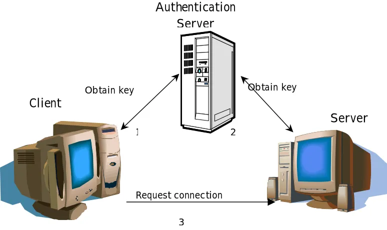
Designed in the mid-‘80s at the Massachusetts Institute of Technology (MIT), the Kerberos network protocol is designed to provide secure Authentication between one or several parties. Kerberos [19] uses a cryptographic distributed service system. In Figure 2-3 we show the simplest scenario, which involves three parties: a client or
user, an application server or verifier, and an Authentication Server (AS). In order to establish a connection between the client and the server/verifier, the client needs to prove to the verifier its identity by means of an encrypted key. Neither the verifier
nor the client hold any encrypted keys. Only the AS provides the keys. So the process is the following: (1) the client connects to the AS to obtain a key. (2) The
Client
Server Authentication
Server
Obtain key Obtain key
Request connection
1 2
[image:23.612.135.522.95.325.2]3
Figure 2-3 Authentication process to establish an encrypted communication between a client and a server using Kerberos
2.2.1.2 SSL/TLS
The Secure Socket Layer [1] (SSL) and Transport Layer Security [2] (TLS) Protocols are security protocols that use cryptography to provide privacy. These protocols provide “integrity between two communicating applications” by means of (1) a private connection – “using data encryption and transaction of keys” and (2) a reliable connection – “the message includes a message integrity check using a keyed MAC.” More information, libraries, and software toolkits can be found in the OpenSSL Project [20] website.
Therefore, the communication and transaction of keys is only performed between a client and a server, there is no need of a third party to hold keys.
2.2.2
Intrusion Detection
The purpose of Intrusion-Detection Expert Systems (IDES) is to detect suspicious or abnormal use of a system. An IDES works as a system monitor of all the activities performed in the targeted system.
There are two types of detection techniques: anomaly detection and misuse detection. The former “uses models of the intended behavior or users and applications, interpreting deviations from this ‘normal’ behavior as a problem [21].” In other words, it keeps an activity log of either the users or the applications used of a system. When it finds an activity different than what is normally used for, it will flag the activity as suspicious.
2.2.3
Firewalls
Our research focuses on the free available Linux firewall iptables. In this section we describe what a firewall is, the ways to implement it, the types, and the architectures.
A firewall is the front line defense mechanism against intruders. “It is a system designed to prevent unauthorized access to or from a private network. Firewalls can be implemented in both hardware and software, or a combination of both [23].”
Firewalls can be implemented in two different architectures [24]: single box (Figure 2-4) and as stand-alone edge device (Figure 2-5). Our research focuses on firewalls in a single-box. The firewall in a single box is designed to protect only that single machine. Usually, only outgoing connections are allowed and all incoming connection requests are rejected. On the other hand, a stand-alone edge device can be a router or a dual-homed host. A router is a device that forwards packets between different subnets. A router firewall is a router that can filter packets, block ports, maintain stateful-inspection, or do some other type of filtering. A dual-home host is a single computer, with at least two network interface cards, serving the function of a firewall router.
Internet
Figure 2-4 A Single-host Firewall protects only one computer
susceptible to IP spoofing – a technique used to gain unauthorized access to computers, whereby the intruder sends messages to a computer with an IP address indicating that the message is coming from a trusted host. Proxy servers, on the other hand, intercept all the messages entering and leaving the network but it differs in that the proxy hides IP addresses of the clients in the internal network.
Figure 2-5 Example of a Router Firewall protecting multiple computers inside a network
2.2.3.1 Future of firewalls
In 1997, Scuba and Spafford from COAST Labs submitted a paper describing a model or framework for the design of firewalls [28]. According to them, firewalls should provide authentication –provide assurance of the integrity of the connecting host or server, integrity – “shielding communication traffic from unnoticed and unauthorized modifications such as insertion, replacement or deletion of data,” access control – to provide a dynamic mechanism that generates questions about a particular traffic (e.g. IP x.x.x.x wants to establish connection on port 21, do you want to allow this connection?) Audit –keeping track of connections/traffic flowing through the firewall, also referred as “log files.”
Some of these functions (e.g. authentication and audit) are built in CISCO’s IOS [27]. However, personal firewalls do not provide authentication but some of them, such as McAffee’s personal firewall [26], provide dynamic access control where the user is notified “on the fly” if a certain IP address desiring to establish a connection should be allowed or not. So, personal or end-client firewalls are still under development.
Chapter 3
Firewall Performance Study
A firewall is “a device that enforces an access control policy between networks [30].” Firewalls can be used in two ways, as a stand-alone edge device that protects and forwards packets to a local area network or as an operating system component for protecting a single host. As we will see, researchers have focused on studying the
latency, throughput, and total transaction time of a firewall as a stand-alone edge device, but we were unable to find peer-reviewed research papers that specifically addressed the performance of the firewall on a single host. For this reason, our investigation focuses on studying the performance of single-host firewalls, and specifically on the Linux firewall iptables.
By the time our research began, we were unable to find documentation that depicted the exact path that a packet follows as it traverses the network stack. Thus, our first efforts focused on capturing this path. Once the path was captured, we performed our first tests. The purpose of the first tests was to understand the firewall sensitivities and the performance impact on the host by varying the transmission speed, payload size, INPUT policy, number of rules, and packet transmission protocol.
3.1 Previous Research
There are two different goals for testing firewalls. The first goal is to analyze and test the firewall policies, in other words, modeling and testing how secure a firewall is in a “real-world” environment. The second goal to test the firewall performance.
3.1.1
Analyzing and Testing Firewall Policies
Most experts would agree that the most difficult part in the design of a firewall is the process of defining the security policy and the configuration of the firewall [31]. The configuration is the process of deploying the policy. To define the policy means to understand the network topology of the LAN, decide what services will be allowed, and who will have access to what information.
Various research papers have presented methods that could serve as a basis for testing firewalls that protect internal networks. Vigna proposes a mathematical model for firewall “field-testing” taking into account the topology and operational environment and not the internal architecture of the firewall [32]. Another method presented is the Firewall ANalysis enGine (Fang) [33]. Fang is a tool that “reads relevant configuration files, and builds an internal representation of the implied policy and network topology” to simulate spoofing attacks and the behavior of the firewall in response to those attacks. Hazelhurs, Attar, and Sinnapan [34] present a “binary decision diagram” to test the rules of firewalls. All of the above are similar in that they all target to model LANs and not personal firewalls.
firewalls. Vigna says that the current methodologies to test firewalls are mainly based on expertise and individual skill [35]. The reason behind this is because, in business terms, every customer wants a different specification for the network and for its security (e.g. topology, services running). So, experts use hacking tools such as SATAN, Neus, COPS, Internet Security Scanner (ISS), and BSD Monitor to test if the firewall is secure enough to protect a LAN and satisfy the customer’s need.
3.1.2
Testing the Performance of the Firewall
3.1.2.1 Router firewalls
A firewall router reads header information of a packet, checks the header with a number of rules, and decides to forward the packet or not. Various studies have been made on router firewalls. In [27], Patton, Doss, and Yurcik compared the performance of open source versus commercial firewalls. So, they compared the old Linux ipchains included in RedHat version 6.0 against CISCO’s IOS firewall, the latter consisting of hardware and software. At the time, the older Linux netfilter (ipchains) had the disadvantage of lacking functionality; it was not a stateful
firewall while IOS was.
“The results show that the Linux firewall has consistently higher transaction throughput rates than the Cisco’s stateful firewall for rule sets varying from 0 to 200 rules and for packet sizes of 1 and 128 bytes [27].” No specifics were given on the rule set used.
clients inside a LAN connecting to a server outside the LAN and a router firewall sitting in between the networks. The firewall would be configured to 7 different policies, one for each HTTP and FTP test. The clients would run a script to establish the connections. The tests for HTTP and FTP were performed independent from one another. For HTTP tests, the clients made connections to download small sizes of data. On the other hand, for FTP tests the client would make small or large number of connections and download files of either 1MB files during one test or 5MB files in another. Those tests were also independent from one another.
The results implied that “the performance difference among security levels due to the overhead of packet filtering for more security is negligible when compared with the outside traffic interface [35].” In other words, performance decreases as the number of connections increase, and is not affected by the security policy. Unfortunately, no specifics were given on the rule-set.
Other tests, such as [36] [37] and [38], have been performed to compare commercial router firewalls, but the results are not presented in this document because they are out of the scope of our research.
3.1.2.2 Single-host firewalls
size per packet was 3,700 bytes. The throughput was measured by dividing the size of the bit stream by the time (in seconds) to receive the stream. Finally, the input policies (i.e. INPUT/ OUTPUT/ FORWARD) were set to ACCEPT. The results of the four tests are described below.
On the first test, without a firewall and with one single connection, the throughput was 9.09 Mbits/sec. The CPU utilization was not provided. Another test running “real-world” iptables rules and one single connection showed a 9.10 Mbps and a CPU utilization of 19-23% on the sender and 16-20% on the receiver. Another test included establishing five TCP connections and no rules, in order to measure the CPU impact by TCP/IP traffic. The sum of the throughput was 9.13 Mbps, and the CPU utilization varied from 19-20% on the sender and 15-18% in the receiver.
3.2 Terminology
As we have seen, firewall performance has been studied in terms of the latency, throughput, and total transaction time. In those tests the parameters used have been the number of rules, the number of connections, and the number of bytes per packet or per file, the type of download (e.g. HTTP and FTP).
Some of the researchers have used the firewall-benchmarking terminology defined in the RFC 2647 [30]. However, we had to redefine some terms to make them applicable to our investigation.
Earlier studies made by the Cal Poly Network Project Research Group (CPNPRG) on the performance of the Linux and Windows [29] have been made on the sending operation, that is, a study of the latency and throughput when a packet is sent from the application layer until the data is sent out to the wire. Our study focuses on the receiving operation, and specifically, in studying of the performance impact produced by a firewall when a packet is traveling up the stack.
3.2.1
Performance Metrics
DATA LINK
TCP/UDP
IP LAYER
DATA
STREAM
End of the payload - d2 Beginning of the payload - d1 BOTTOM - T1
TOP – T5
[image:35.612.200.423.79.414.2]SOCKET
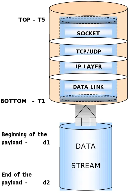
Figure 3-1 Example of a packet in order to measure its latency to traverse the stack
Start latency = T5 – T1 of each packet [seconds]
Stop latency = T5 of the last packet – T1 of the first packet [seconds] Payload throughput = (payload size) / (stop latency) [bps]
From Figure 3-1 the start latency can be defined as the period of time the
beginning of the packet’s payload (d1) to reach the bottom of the stack (T1) until the
of the payload reaches the top of the stack. The stop latency can be affected by packets that are dropped by either the network or by the host’s TCP/IP stack because, if a packet is dropped, the stop latency will include the start latency plus the time that it takes for TCP to ask for retransmission and the packet to be retransmitted.
Start and stop latency are equal to each other when the payload is less than or equal to the maximum transfer unit (MTU) minus the Ethernet headers. Firewall overhead in the protocol latency, or just overhead, is the impact in the processing time caused by the firewall as it processes every packet header.
The following terms will also be used in this document: Packet, used interchangeably with Ethernet frame, includes all the headers plus the payload.
Payload is the information data encapsulated inside the Ethernet frame excluding all
headers. The throughput is the “measure of the rate at which data can be sent through the network, and is usually specified in bits per second [40]”. The protocol throughput is the amount of data that a protocol stack can process per unit of time (Kbps or Mbps). The payload throughput is the amount of payload that the DUT can process per unit time. It is calculated as follows1:
Payload throughput = (size of the payload) / (stop latency)
3.2.2
Parameters to determine the firewall sensitivity
As mentioned earlier, firewalls have been tested by modifying a set of parameters such as the number of rules, the number of connections, the number of bytes and the transmission rate.
Our investigation focuses on analyzing and testing the sensitivity of the firewall, and the performance impact generated by it, by varying a set of external and
internal parameters presented in Figure 3-2. External parameters are those that cannot be controlled by the firewall such as transmission protocol, transmission speed, and payload size. Internal parameters are those that can be controlled by the firewall such as Input policy, filtering type, and number of rules.
Protocol Transmission speed Filter Type Number of Rules TCP UDP
4 sec delay in between
packets
Bursts: 10 | 20 | 50 75| 100 Mbps
MAC IP TCP UDP ICMP 10 40 100 Input Policy ACCEPT DROP Payload Size 64 128 256 1.4K … 64 K
External Parameters Internal Parameters
Figure 3-2 Parameters to determine the sensitivity of the firewall
analyzing the performance impact as it traverses the stack. The second test consists on tracing a stream of packets at various transmission rates. We explain the two scenarios below.
3.3 Tests definitions
There are two main issues to resolve in the two scenarios just mentioned above, and they can be summarized in two questions: (1) Does a single packet carry enough information to explain the sensitivities of the firewall? (2) Will the measurements obtained for single-packet tests be sufficient enough to measure the performance on the host?
The data collected from tracing a single packet in the stack should provide enough information to find a time approximation of the sensitivities of the firewall and the total processing time to the parameters already presented. On the other hand, multiple packets will provide more “accurate” results. This can be explained with the following example: think of the operating system to be analog to the plumbing system of a kitchen sink. Imagine that you desire to know how long would 100 liters of water take to pass through the plumbing. There are two ways to measure the time: the first way is by pouring one liter of water and multiplying it by 100; the second way is to drain the 100 liters.
former is a clean and fast way to find an approximation of the total time to complete the system because, whether we pour 1 or 100 liters, the water will flow through the same path. On the other hand, the latter will provide more “accurate” results because they include the rate at which the water was expelled from the faucet and the pressure exerted by the mass of water pushing down the pipe.
Just as the water flows through the same path, in the same way, packets follow the same path when they traverse the TCP/IP stack. Consequently, single-packet tests are analogous to pouring only one liter at a time. These tests will provide an approximation of the time that a packet is held at each point in the stack. Furthermore, throughput or multiple packets tests at various rates are analogous to pouring 100 liters at one time because they take into account the queuing of packets by the OS, the processor speed, and the rate of transmission.
In this thesis, only single packet tests are performed to understand and measure the sensitivities of the firewall. They also provide a conservative approximation to the actual latency for multiple packet tests.
3.3.1
Single-packet tests
traverses throughout the stack. The files modified are: dev.c, ip_input.c, tcp_input.c,
udp.c, and socket.c. At boot time, both machines will start in run-level 3. During the tests, no services will run in the background, see Appendix B and C for details on how to run the tests and to see the scripts. Libra, the client, is a 233MHz Pentium II processor. Both machines are isolated from any outside traffic and connected through a 100 Mbps 3Com switch. Refer to Figure 3-3 to see the test bed.
DUT: Volans
CLIENT: Libra
3Com switch
Figure 3-3 Test setup to measure the latency when a single packet is sent every 4 seconds
Single packet tests procedures are included in Chapter 4. See Appendix C for the source code used to generate the rules.
3.3.2
Throughput tests
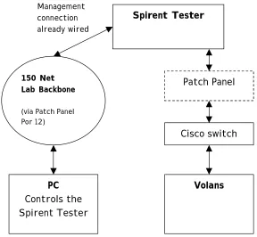
Throughput tests are performed using the Spirent’s Network Tester “SmartBits”. These tests will show the latency of the network stack when multiple packets are sent at different transmission rates.
model ML-7710, are connected via the patch panel to a Cisco 2900 XL switch to communicate with our DUT, which is Volans. The test bed is shown in Figure 3-4.
Spirent Tester
PC Controls the Spirent Tester
150 Net Lab Backbone
(via Patch Panel Por 12)
Patch Panel
Volans Management
connection already wired
[image:41.612.172.460.158.424.2]Cisco switch
Figure 3-4 Test setup using the Spirent’s network tester to vary the throughput
Two SmartBit cards were connected to the switch, one is to send the stream of test packets at different rates, and the other is used to send 2 packets to port 6789 which serves to reset the memory buffers where the measurements are stored. During the tests, the Smartbits would run for one minute before the timestamp measurements were taken. This is because we considered that one-minute would be enough to reach steady-state for the transmission rate performance testing.
counter was added to the code so that the timestamps would be taken after one minute. The number of packets sent in a minute is automatically obtained with the SmartWindows application. The second modification was to increase the memory buffers in order to store 4000 timestamps instead of 50 as it was before. A third modification was to match incoming packets on the port number instead of reading the payload. One last change had to be made to the instrumentation code inside the
netif_rx function. Since netif_rx executes with interrupts disabled and I/O operations are costly, we removed the only memcpy from our instrumentation code.
3.3.3
Packet specifications
The test’s packets must be less than the MTU because of fragmentation. If the payload is larger than the MTU, by nature, the protocol stack will fragment the payload into packets, one(s) that will have the size of an Ethernet frame with the last one possibly having a payload less than an Ethernet frame. Having to deal with different payload sizes in a test may cause a discrepancy and could ruin the results, or at least make the results difficult to interpret.
3.4 The Linux TCP/IP stack
3.4.1
Understanding the packet data flow
netfilter/firewall hooks specific to the Linux kernel 2.4 other than the source code. Thus, our first efforts focused on capturing the data flow from the data link layer to the application layer and finding the netfilter hooks. On the other hand, by the time this document was written we found documentation (sections 3.6.2 and 3.6.3) that confirmed our findings.
3.4.1.1 The receiving operation
From the basics of networking we understand that in order to establish a TCP connection a server must be listening to an open port. A client wanting to establish a
connection sends a SYN packet to the server. The server responds by sending a
Figure 3-5 Basic TCP client-server connection
3.4.1.2 Analysis from the application down
When a server application opens a connection and is ready to receive a packet, it will make a call to read( ) or recv( ) on a socket. Then, read( ) makes a system call to
sock_read( ). The latter will call sock_recvmsg( ), which will then call sock->ops->recvmsg( ). For a TCP connection the “ops” corresponds to a pointer to inet, where
[image:45.612.172.487.323.620.2]inet calls the recvmsg( ) function. Finally, the inet_recvmsg( ) calls sk->proto[tcp|udp]->recvmsg( ) and the application sleeps. The latter is put into the run queue or is woken up after the TCP layer has processed any incoming packets. Figure 3-6 shows this process.
read( )
sock_read( )
sock_recvmsg( )
sock->ops[inet]->recvmsg( )
recvmsg( )
inet_recvmsg( )
sk-proto[tcp/udp]->recvmsg
SLEEP
Application Layer
Socket Layer
3.4.1.3 Analysis from Datalink layer to Socket layer
Initially, as a packet comes in from the physical layer it causes the Ethernet device to “fire up” an interrupt. Interrupts are handled by top-halves and bottom-halves [43]. The top-half is handled by the network adapter’s device driver (e.g. 3c59x.c). The device driver calls the eth_type_trans() function located in the eth.c file. This function organizes the first part of the packet header (i.e. MAC header) inside an sk_buff structure.
All the information contained inside a packet is carried out through the stack
in the form of an skbuff structure until we get to the socket layer. In the Linux
source code we always find a structure skb of type skbuff. So, for example,
when a packet enters from the network, skb->data points to beginning of the
entire information of that incoming packet. The data is not organized in the skbuff structure all at once but, as the packet passes through the stack, each layer will
reorganize the packet’s information inside that skb structure. After the TCP/UDP
layer has been processed, it will pass the pointer to skb structure to the socket layer.
The socket layer will extract information inside the skb structure and create a new
structure of type sock. Thus, the sock structure will contain information such as source and destination port, the pointer to the payload, and more. More details on the information inside these structures can be found in the sock.h and skbuff.h files of the Linux source code.
Going back to the execution of the top-half, when the eth_type_trans
in the usr/src/linux/net/core/ directory. Two main functions separate the
top-half from the bottom-half: netif_rx() and net_rx_action(), respectively. After the top-half executes, the swapper will be in charge of running the bottom-half. Note that it is the swapper and not the scheduler who handles this operation. The difference between the swapper and the scheduler is that the swapper is in charge of completing the execution of the pending bottom-halves [43] and the latter is in charge of handling processes.
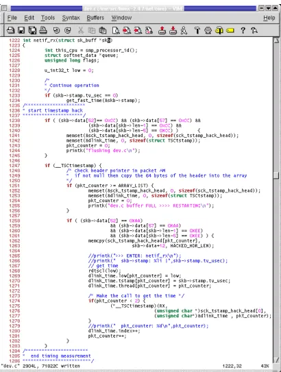
The netif_rx() function takes a timestamp by calling the
get_fast_time(&skb->stamp) function. This timestamp serves as a unique ID for each packet. This packet ID is transferred throughout the entire stack inside the
skb structure, serving as a mean to match/differentiate the measurements for a specific packet at each layer. After the top-half executes, the swapper schedules to
execute the bottom-half which starts with net_rx_action().
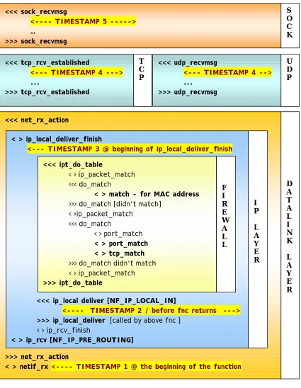
Figure 3-7 presents the example of a single packet traversing the TCP/IP stack with a firewall of two rules, matching a MAC address and a TCP port. The packet is traced through all the layers of the stack until the socket layer hands the data to the application. The symbols in Figure 3-7 represent the following:
< > enter and exit function ( ) >>> enter function ( )
<<< exit function ( ) . . . several functions
because the MAC header is “stripped off” along with the IP header right before the net_rx_action() function exits.
<<< net_rx_action
>>> net_rx_action
< > netif_rx <---- TIMESTAMP 1 @ the beginning of the function
D A T A L I N K L A Y E R < > ip_local_deliver_finish
<--- TIMESTAMP 3 @ beginning of ip_local_deliver_finish
<<< ip_local deliver [NF_IP_LOCAL_IN]
<---- TIMESTAMP 2 / before fnc returns ---> >>> ip_local_deliver [called by above fnc ]
< > ip_rcv_finish
< > ip_rcv [NF_IP_PRE_ROUTING]
I P L A Y E R <<< tcp_rcv_established
<--- TIMESTAMP 4 ---> ... >>> tcp_rcv_established T C P <<< sock_recvmsg
<---- TIMESTAMP 5 ---> … >>> sock_recvmsg S O C K <<< ipt_do_table
< > ip_packet_match <<< do_match
< > match - for MAC address >>> do_match [didn't match]
< >ip_packet_match <<< do_match
< > port_match < > port_match < > tcp_match >>> do_match didn't match < > ip_packet_match >>> ipt_do_table F I R E W A L L <<< udp_recvmsg
<--- TIMESTAMP 4 --> ...
>>> udp_recvmsg
[image:48.612.109.534.151.699.2]U D P
Notice the timestamps placed throughout the stack in Figure 3-7; these are placed at critical points in order to take timing measurements in the stack. Timestamp 1 is our reference point (“T1” in Figure 3-1). Timestamp 2 is placed before the firewall starts its execution. Note that this is not the point where the IP layer begins, but the point where the netfilter/firewall begins. Timestamp 3 is placed after the firewall has processed the packet and has finished its execution. The difference between the measured values of Timestamp 3 and Timestamp 2 tell us the cost of having a firewall.
Timestamp 4 is placed after the TCP or UDP layers have been processed. At first, we speculated that if we block on TCP ports or MAC addresses, filtering should happen at the TCP layer or at the Data Link layer respectively, but Figure 3-7 proved us wrong. Finally, Timestamp 5 (point “T5”of Figure 3-1) is placed before the socket layer passes the payload to the application.
Once the path followed by a packet in the stack was studied, we performed various tests. To understand the results we found it necessary to study the source code and the iptables algorithm, which is explained in the last section of this chapter.
3.5 Software instrumentation
3.5.1
Software design and issues
MAC header | IP header | TCP header | AAAAA******** *********************EEEEE
measurement results showed that some of the packets were missing at the TCP and socket layers. It was not until we ran the network sniffer that we found the problem to be in the client application and in the timestamps implementation. Timestamps were taken for every single packet coming in from the network. For the client application, every time that the client would send a packet it would close the connection, re-negotiate with the server, and send the packet. So, when packets were “lost” it was because our instrumentation was taking measurements for ARPs, SYN, ACKs and other packets which do not traverse all the way up to the socket layer!
Another problem encountered was running other services, such as Xwindows, system logger, and NIS. Since we had a timestamp at this layer, the timestamp code would be called constantly, thus, taking measurements that did not belong to our test packets. NIS was the worst of them because both PCs would constantly send ARPs to find the NIS server and undesired packets kept coming in. The best solution was to shut down all the services (which we did later in our tests) but, if we wanted to have different traffic coming in, how do we identify our test packets? Well, we marked the payload. So we changed the hub for a switch and marked the payload with A’s at the beginning of the data and E’s at the end, just like this:
entire packet. So, when a packet comes in through the network, skb->data[0] points to the beginning of the MAC header. Then, in order to read the A’s and E’s of the payload, we have to offset skb->data to the beginning of the payload. For
example, for a TCP packet the first A is at offset 52, (i.e. skb->data[52] – see
Figure 3-8) and for a UDP packet the offset is at 29 (i.e. skb->data[29]). As the packet traverses the stack, the offset decreases because the layers modify the structure and strip off some parts of the header.
3.5.2
Instrumentation of the Timestamps
The performance measurement timestamps are taken by using the rtdscl macro. This macro reads the lower 32 bits of the Time Stamp Counter (TSC) using assembly instructions thus, giving a more precise time [43].
3.5.2.1 Timing measurements at the Data Link layer
As it has been explained, we place the first timing measurement inside the
netif_rx() because this is the starting point of the stack. Only the packets marked with A’s and E’s will be measured. The skb->data is the pointer to the
beginning of all the data. At this point in the stack skb->data[0] points to the
beginning of the IP header. The payload starts at skb->data[52] for TCP and for
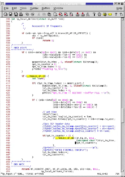
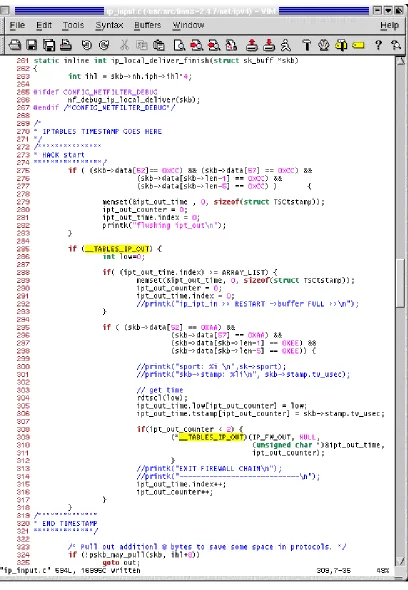
3.5.2.2 IP Layer
Theoretically, when a packet traverses throughout the stack the operating system should strip-off the header of each layer as it moves up. As mentioned earlier, in the Linux kernel, the MAC and the IP headers are not stripped-off until the firewall has processed the packet.
Timestamps 2 and 3 are taken at this layer to measure the firewall. Timestamp 2 is located right before the ip_local_deliver() returns. This is because when this
function returns it makes a call to NF_IP_LOCAL_IN. Timestamp 3 is placed at the
beginning of ip_local_deliver_finish. Notice in the Figures 3-9 and 3-10
that the calls to __TABLES_IP_IN and __TABLES_IP_OUT are the entry points to take the timestamps. When our instrumentation is not loaded, the addresses of
__TABLES_IP_IN and __TABLES_IP_OUT point to NULL. Again, the timestamp is taken using the rdtscl macro. In order to reset the memory buffers, we send a packet marked with C’s at the beginning and at the end of the payload. Thus the ‘if’ statement:
if ((skb->data[52] == 0xCC) && (skb->data[57] == 0xCC) && (skb->data[skb->len-1] == 0xCC) &&
(skb->data[skb->len-5] == 0xCC) )
3.5.2.3 TCP and UDP layers
The timestamp is taken at the top of the TCP and UDP layers. For TCP the pointer to the payload is skb->data[0], but for UDP the pointer to the payload is at
[image:56.612.122.505.181.686.2]skb->data[8], See Figure 3-11 and 3-12.
3.5.2.4 SOCKET layer
[image:58.612.118.511.178.636.2]The socket layer is the portion of the stack that forwards the data to the application layer. At this point we can no longer match the A’s and E’s of the payload, so we trace the packet using the port that it is destined for (i.e. 12345). See Figure 3-13.
3.6 The Linux Firewall – IPTABLES
3.6.1
Iptables Application
The Linux iptables was introduced with the 2.4.0 kernel to replace ipchains.
With iptables the user can create and delete chains and matching rules to filter packets. There are 3 default policies: INPUT – to check the headers of incoming packets, OUTPUT – for outgoing packets/connections, and FORWARD – if the machine is used as a router (e.g. as a Network Address Translator.) Each policy has its own set of rules.
Basically, rules are instructions with pre-defined characteristics to match on a packet. When a match is found the firewall makes a decision to handle that packet. Each rule is executed in order until a match is found. A rule can be set like this:
iptables [table] <command> <match> <target/jump>
See the example below:
#iptables –P INPUT ACCEPT
#iptables –A INPUT –p tcp –dport 23 –j DROP #iptables –A INPUT –p udp –dport 80 –j DROP #iptables –A INPUT –p icmp –j DROP
Where: –P: policy; –A: append; –p: protocol; –dport: destination port; –j: jump
Iptables and ipchains, ironically enough, have the benefit of “chains”!! Chains are basically a sublayer of rules so that, if we want to capture a packet with specific characteristics, it is efficient not to make it go through the rest of rules that might never match that specific packet.
Figure 3-14 Iptables configuration Process
subnet 192.168.X.X. Also, for those specific packets belonging to that subnet, the user wants to accept TCP packets destined to ports 21 and 80, and UDP packets destined for ports 81 and 12345. In that case, the configuration of the firewall looks like this:
#iptables –P INPUT DROP
#iptables –A INPUT –s 192.168.0.0/16 ACCEPT #iptables –N tcp_packets
#iptables –N udp_packets
#iptables –A INPUT –p tcp –j tcp_packets #iptables –A INPUT –p udp –j udp_packets #iptables –A tcp_packets –dport 21 –j ACCEPT #iptables –A tcp_packets –dport 80 –j ACCEPT #iptables –A udp_packets –dport 81 –j ACCEPT #iptables –A udp_packets –dport 12345 –j ACCEPT
In the example, we have specified to drop every packet except those packets coming from the subnet 192.168.X.X, and they should be checked under the rule set.
We create two chains, tcp_packets and udp_packets. Under each chain we create a set of rules to match the packet and with the rule we specify a target (e.g. ACCEPT / DROP / REJECT / QUEUE / RETURN). A TCP packet coming from the trusted IP will be checked under the tcp_packets chain. Inside that chain we check if the packet is destined for ports 21 or 80. If it is not destined for any of the two ports the packet is dropped. Only TCP packets will be checked under the
3.6.2
Architecture of the Netfilter
2The Linux Netfilter consists in a series of “hooks” placed in several points in the network stack – so far IPv4, IPv6 and DECnet.
Figure 3-15 Packet traverses the netfilter
In Figure 3-15 a packet comes in from the left hand side of the picture. The first check point to the netfilter’s framework is the NF_IP_PRE_ROUTING [A] hook; this is after the packet has passed simple sanity checks, such as not truncated, IP checksum OK, not a promiscuous receive. The routing code will decide whether the packet is destined for another interface, or for a local process. Packets that are unroutable may be dropped.
2The information provided in sections 3.6.2 and 3.6..3 have been taken, and some parts even copi ed, “as is” from the “Netfilter
If the packet is destined for the box itself, the netfilter’s framework NF_IP_LOCAL_IN [B] hook is called. The analysis of the performance of the firewall starts at this point.
However, if the packet is destined to another interface, the netfilter framework is called for the NF_IP_FORWARD [C] hook. Finally, the packet is passed to the NF_IP_POST_ROUTING [D] hook it goes out to the outside.
When packets are created locally and the netfilter has been configured to filter outgoing traffic, the NF_IP_LOCAL_OUT [E] hook is called. Here, “routing occurs after this hook is called - in fact, the routing code is called first (to figure out the source IP address and some IP options) - if you want to alter the routing, you must alter the ‘skb->dst’ field yourself, as is done in the NAT code.”
3.6.3
Netfilter Base
The firewall is modular; this means that the network hooks will only be called when a rule has registered that hook. Rusty Russell explains, “Kernel modules can be registered to listen at any of these hooks. A module that registers a function must specify the priority of the function within the hook.” In other words, when creating a module, the module should specify what netfilter hook(s) will be used so that “when a netfilter hook is called from the networking code, each module registered at that point is called in the order of priorities, and is free to manipulate the packet.” The module can then tell netfilter to do one of five things:
1. NF_ACCEPT: continue traversal as normal
3. NF_STOLEN: I’ve taken over the packet; don’t continue traversal 4. NF_QUEUE: queue the packet (usually for userspace handling) 5. NF_REPEAT: call this hook again
For example, when using Network Address Translation (NAT), “for non-local packets, the NF_IP_PRE_ROUTING and NF_IP_POST_ROUTING hooks are perfect for destination and source alterations respectively;” this is because pre-routing checks on the destination address of the packet and makes a decision to forward it or pass it to the host itself. Post-routing checks if the packet is allowed to be forwarded or not. More detailed information can be found in [22].
3.6.4
Iptables Algorithm
The iptables algorithm will explain the results in Chapter 4. Notice what happens when the netfilter’s framework NF_IP_LOCAL_IN hook is called in Figure 3-16.
Figure 3-16 IPTABLES Algorithm – ipt_do_table( ) checks for matches in the rule-set
[image:65.612.106.523.68.462.2]Figure 3-17 ip_packet_match function–IP address are always checked regardless of the type of filtering in the rule-set
After passing through the ip_packet_match and finding no matches, the
next step is to execute the IP_MATCH_ITERATE, in Figure 3-16. Here, the
firewall calls the do_match function pertaining to the specific rule. Every module has a specific do match function. In other words, if we are filtering/matching a MAC address the iptables algorithm will call the do_match function specific to MAC addresses. If a match is found, the chain breaks to perform a TARGET check. Targets can be ACCEPT, DROP, QUEUE, STOLEN, REPEAT or “JUMP” to
[image:66.612.110.499.70.368.2]Iptables breaks out of the loop when it finds a match, when the packet is a fragment, or when all the rules have been checked. Hotdrop is a variable initialized to zero; when a packet is a fragment the hotdrop variable is changed to a 1, which indicates that the packet should be dropped. A fragment is a malicious packet (e.g. a packet with a TCP header larger or smaller than the standard) and will always be dropped. The VERDICT is a variable that tells the algorithm what to do with the packet (e.g. NF_ACCEPT, NF_DROP).
Chapter 4
Firewall Performance Results
In this chapter we will compare the host’s performance with and without the firewall. We will analyze the data in terms of the host’s latency for a single packet and also for a stream of packets when they traverse the stack. The analysis of the latency for a single packet will show us the firewall sensitivity to the number of rules, the type of filtering (also referred as the type of matching), and the payload size. For both scenarios, single packets and throughput tests, the latency will show how the total processing time is impacted by the transmission rate. The chapter