INTERNATIONAL CONFERENCE ON ENGINEERING DESIGN ICED 03 STOCKHOLM, AUGUST 19-21, 2003
A FUTURE VISION FOR THE ENGINEERING DESIGN ENVIRONMENT:
A FUTURE SOCIOTECHNICAL SCENARIO
Richard Crowder, Rob Bracewell, Gareth Hughes, Micky Kerr, David Knott, Mike Moss, Chris Clegg, Wendy Hall, Ken Wallace and Patrick Waterson.
Abstract
This paper presents a future vision for the working practices of designers within a manufacturing organisation. By its very nature the engineering design environment is highly distributed in nature and is characterised by a large number of information sources, which together with the designers forms a complex sociotechnical system. In discussions with designers it is apparent that changes are required to this environment to reflect the changes in the design process and organisations. We have developed a scenario that incorporates many of the features requested by designers and managers to improve the design environment. The scenario sets out a route map for the development of technical and social tools that aid the designer.
Keywords: Knowledge Management, Aerospace Engineering, Design Reuse.
1.
Introduction
The engineering design environment is highly distributed in nature and is characterised by a large number of information sources, which together with the designers forms a complex sociotechnical system. The paper by Wallace et al [1], discussed an outline for the future vision of the engineering design environment, and concluded that a range of knowledge management tools would be required to support their vision. Since that paper was presented the Knowledge Capture, Storage and Reuse (KCSR) project has been completed. One of the objectives of this work was to define a future engineering design environment, with particular emphasis on the social and technical systems that will support designers in their day-to-day activities.
how they interact with the cycle. As will be recognised the requirements of knowledge engineering will significantly change the working methodology of the designer, both technically and socially. The purpose of the paper is to present one possible future design environment that could be used within a manufacturing organisation. The future design environment is presented as a scenario, allowing the requirements of the two technology demonstrators, the Expertise Finder and the Design Rationale Capture tool, to be defined.
2.
Methodology
In order to determine the future requirements of the engineering design environment we gathered a considerable amount of information through a number of exercises including, extensive interviews with designers and their managers, allocation of function exercises [4], and the analysis of the current design practice. The results were developed into a detailed scenario which was evolved through discussions with the current design community. The scenario adopts a socio-technical perspective in dealing with the capture, sharing and re-use of knowledge within the design context. As such, the ideas and practices outlined throughout the scenario promote a complementary social and technical approach to managing knowledge in the engineering design process of the future. Aspects of the social and technical implementation of the scenario were considered in detail as part of the project, and are detailed in associated papers, [5, 6]
3.
The Scenario
The scenario presented is not intended to be the detailed script for future work, but rather a resource for discussing the design process, for planning the research activities to realise the vision and for clarifying the interests and concerns that motivate it.
In the scenario it is assumed that the technical elements of the future design environment have been embodied in an application termed KTfD (Knowledge Tools for Designers). The proposed architecture is shown in Figure 1, showing that all the information required can be accessed through the KTfD desktop. It is recognised that populating the databases and the associated links is a key issue. All objects within the KTfD database are version controlled and the system is configured so that all documents are stored locally, ensuring that they are available even if the original source is irretrievable.
In this scenario one of the key tools for the designer is a portable electronic logbook or tablet PC. These A4 or A5 sized systems are equivalent to a conventional logbook and have handwriting recognition software, together with software to resolve sketches, and provide interfaces to specific engineering packages. As shown in Figure 1 KTfD is able to access information from anywhere in the design office, through the local wireless network. The electronic logbook gives a degree of pervasive computing to the user, as it permits active reconfiguration as a function of location. It should be recognised that the KTfD is not only for knowledge management, but also has access to the full range of office and data analysis tools. It is recognised that to implement this system, work will be required in standards, web services and ontologies.
Zed's workstation
PDA and Pen computer
Company wide resources WWW resources
Other designers
Digitizing pad
Test f acilities across the
company
Team Leader
Conf erence room
PDM
[image:3.595.154.448.71.369.2]Local data base
Figure 1. KTfD architecture
3.1.
The design task
Zed is the design engineer who has been asked by a Team Leader to resolve a problem relating to the bonding of a perforate to an aluminium honeycomb. Zed meets the Team Leader informally, during which Zed make notes on a pen computer. The meeting covers the details of the problem and background information. Following the download of the notes to Zed’s workstation and the retrieval of related information, Zed has a complete understanding of the background to the problem.
Using the KTfD desktop, the Team Leader initiates the activity by retrieving the debonding problem report from the PDM system and defining it as a new KTfD prime issue to be resolved, in a new design folder1. As part of the definition process a new job
number is issued, together with links to the background information.
In our scenario the management protocols specify that only a designated team leader can define a new prime issue for the design team to work on, and subsequently confirm that the prime issue is resolved and closed, . The design process concludes with the submission of a final report and the supporting documents and computer files.
Figure 2
Figure 2. Possible KTfD interface as the new issue is added.
3.2.
Obtaining previous work and background information
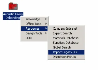
On opening the KTfD workspace, the debonding issue icon is accessible from Zed’s workstation. At the same time Zed downloads the relevant prompt list from the Intranet into the new online design folder, Figure 3. These are automatically translated into issues to be resolved. The issues are classified under various categories and as it is normal practice Zed will discuss the key issues with the Team Leader as soon as possible in order to agree the dates by which they should be resolved. As issues are addressed they change colour to indicate their current status. The colours propagate up the hierarchy so that Zed, his Team Leader and anyone else can see at a glance the progress made.
Figure 3. Adding addition issues etc. Note access is also provided to other resources such as….
Zed looks at the records of discussions, which have taken place in the various communities-of-practice (CoP) over the last few years. After accessing the records, Zed finds that a CoP existed three years ago, having been set up by another engineer. The discussions centre on sharing experiences and possible solutions to the problem. Zed decides that the outcomes from the discussion were relevant to the current situation. The CoP database allows Zed to summarise this information and link it to material that has already captured by KTfD.
One of these documents reveals that there was a debonding problem on a previous product. Browsing the design rationale graph containing this document reveals a primary cause. Zed decides to contact the designer identified against that item through KTfD, but first reviews the presentations given at various design review meetings. Zed examines the meeting hierarchy using KTfD. This provides a map, or trail, through the various meetings. The map links together the meetings that led up to previous attempts to solve the debonding problem. Each meeting provides a link to the electronic documents associated with the meeting. Zed looks at the presentation overheads and transcripts from the meetings; these are in a number of formats and contain different types of information. Reviewing the slides from a meeting Zed is able to assess the nature of the original debonding problem. Zed also examines the solution that had been put forward to solve the original problem and the minutes of the meetings prior to, and after this particular meeting. After tracing though the various meetings, Zed examines the transcripts from design review that were recorded using meeting software (e.g., Compendium [7]) and made use of the IBIS [8] notation to record the design rationale and argumentation underlying the discussions. These transcripts help Zed to trace through the various blind alleys explored by the original design team.
the Cambridge UTP/EDC Design Knowledge Model (DKM) ontology. The latter approach has a number of distinctive features and builds on a combination of design theories and ontologies including the YMIR ontology [12], and the MOKA Meta Model [13]. It is envisaged that KTfD will principally employ the DKM informal model which includes a directed graph, IBIS-derived, design rationale notation. The capture of the design rationale is a major component of the KTfD concept, and tools are being developed to allow detailed design rational capture, [15].
As Zed progresses with the design the PDM workflow records and the copies of the design reports and folders are held locally and will be maintained in synchronism by KTfD. When Zed accesses a document that is external to the company or not version controlled, it is automatically copied to the active DSF. This ensures that the version of the document that Zed has used is accurately recorded. This will prevent problems appearing in the audit trail, if a URL is changed or the source document is updated unbeknown to Zed.
3.3.
Searching for colleagues with prior knowledge
During Zed’s review of the original design reports it quickly comes apparent that this problem has been looked at before. Zed enters a query that searches for colleagues that have prior knowledge of using adhesives to bond metals within a high temperature environment. The results reveal a number of possible contacts across the organisation. Zed contacted a number of the people with the intention of discussing the design problem and the design teams’ proposed solutions.
As envisaged the Expertise Finder will allow the user to primarily find people not documents, i.e. answer the ‘who knows about...’ questions. The system will use design output and rationale to generate a technical profile of an individual, [15]. The solution will exploit linking within the information space, for example between documents, workflow information within PDM, and individual’s job profiles within the HR databases. The general requirement is that the architecture should be modular and flexible and allow questions from multiple viewpoints.
3.4.
Brainstorming with colleagues
As part of the project kick off, Zed had arranged for meeting of interested parties and other designers. This meeting follows on from the first review meeting, which covered the basic statement of the problem along with some initial thoughts regarding solutions and ways forward. The subsequent meetings are recorded by networking Zed’s KTfD workstation into the conference suite’s electronic white board and presentation system. In addition Zed makes notes using a personal electronic logbook. Following the meeting Zed is able to review the minutes; this is made considerably easier as all the information is time stamped. In addition Zed adds some private annotations to the record of output of the whiteboard and minutes, so that ideas can be followed through.
3.5.
The Design Process
It rapidly becomes clear that the problem involves the choice of adhesive and loads to which the bond is subjected. To clarify a number of points, Zed arranges for tests to be undertaken on a number of samples. The results are downloaded directly to Zed’s workstation allowing their rapid analysis. As the analysis of the problem continues, and Zed is involved in discussions with both company and outside specialist, KTfD records these discussions for future retrieval. In addition Zed is encouraged to comment on decisions and documents as the design process evolves.
As the design progresses the team starts to produce engineering drawings and manufacturing specifications. Using a tablet interface, Zed produces a design sketch for discussion at the weekly progress meeting. At the meeting a number of designers comment on aspects of the design, and these are annotated to the final sketch, before it is passed to a colleague to be turned into a manufacturing quality CAD drawing.
In the design process a large number of elements are drawn together, hence KTfD provides facilities to prioritise tasks. As e-mails and other documents arrive Zed will be flagged as to their importance and relevance to Zed’s current activity by active screening. The annotation of documents is a crucial part of the process; KTfD will request that an annotation field is completed after a significant event has occurred. As the design progresses, a decision trail will evolve.
As the work progresses the results of discussions, contact and queries are added to Zed’s record of the design process, these could include test results for a material laboratory, requests to manufacture test components and e-mails to external suppliers for support and quotations. A key part of the designer’s output is the engineering drawings, which KTfD treats as just another form of engineering document. The system will handle a range of sources including conventional CAD packages and sketches drawn using a digital pad. While scanned free hand sketches are against the overall philosophy of KTfD, the facility to input and link to this type of material is provided.
3.6.
Design review meetings
As part of the monitoring process, Zed identified an apparent delay in the programme. On inspecting the design rationale graph it is apparent that a set of test results are holding up the resolution of a specific issue. Zed e-mails the test laboratory to ask for clarification of the delay, before the delay becomes critical.
At the regular review meeting, the team is able to review the current situation regarding the resolution of the problem with senior staff. It is clear that a number of key sub-issues have yet to be resolved; as the meeting progresses it is clear than a slight change of emphasis is required. As the decisions are made, Zed edits the rationale graph, by rejecting a number of issues, and defining a number of other issues that require more information. At the conclusion of the review meeting all the work package modifications and queries are distributed immediately to the team.
designers routinely attend design reviews. Part of their role is to coach less experienced designers in good approaches to design problems. This face to face approach enables experience that is hard to document, or has not been documented to be transferred.
3.7.
Final Approval
To get the design change approved, Zed is required to give a major presentation. All the presentational material is prepared and distributed electronically. The audio of the presentation is recorded (including the discussion) and linked to the individual elements of the presentation. On returning to the workstation Zed attaches this to the on-line final report, and takes the opportunity to complete a pro forma that summarises the achievements of the work. The exported final report with electronic signatures is submitted to the PDM system as part of the approved solution object.
The final report describes the problem being considered and the details of the chosen solution, with the analysis of the problem, and the alternatives explored as linked rationale graphs. Exporting a snapshot of the active documents in the KTfD database generates the final version of the final report to be submitted for approval. The designer(s) create the final report by linking in appropriate pieces of text and graphics contained in to a wider design rationale graph. This consists of a network of issues, proposed answers, arguments and quantitative selection criteria, with attached emails, faxes, models, test result files etc. The on-line final report and design rationale graph are easily browsed, with the ability to follow links in either direction between the two documents. The prime issue can only be formally completed by electronic signatures from a predefined member of staff on the submitted final report.
3.8.
Rewards for Knowledge Sharing
Zed recently had an excellent annual review with his line manager In addition to his current design activities, he was rewarded for the way he was developed a wider role. In particular Zed had been acting as a superuser for the new composite design methodology that was being implemented, and he had been active in the related Community of Practice, specifically set up to help the new implementation and to learn and share ‘good practice’ across all parts of the company.
4.
Feedback on the Scenario
In our discussions with designers and managers the overall impressions of the Zed scenario were very positive. As expected some issues will need further investigation and discussion, however it was concluded the scenario was very much in the right direction. In particular they considered the advantages of the multimedia capability, and capturing and integrating data in a shareable store, with ability to index and timestamp all the information and activities to be a of considerable benefit. The proposed system potentially gets over the widespread problem of forgetting to include all information in the design rationale capture process.
The use of the techniques and concepts proposed in this scenario would tackle a number of cultural issues, including knowledge hording, by working towards a ‘sharing-culture’ within the organisation. The use of the KTfD would increase accountability by making the input of a designer more visible and allow decisions to be more traceable.
It was noted that time pressures make Engineers less willing to adopt IT or new working practices which involve additional effort where the benefit is not to the current project, but to a future project. As a result the KTfD vision is to reuse information generated as part of project work wherever possible. Where additional capture is required motivation is vital. The motivation to use design rationale tools is twofold: First the process of capture supports the designer in clarifying decision making. Second it relieves him or her of a burden in retrospectively documenting the design at the end of the task.'
5.
Concluding Comments
In looking at future systems, there tends to be a presumption that all processes should be based on IT systems; in our discussions with the designers this was strongly resisted. They were only willing to move to automated systems if there was a clear advantage in doing so. One of the key issues for them was for any system to be accurate and reliable. If these are not achieved, people will not trust the system, and hence not use it. Whether or not an automated system can be accurate and reliable enough for certain activities, as discussed in the scenario is still an open research question. In many cases the designer may not fully understand exactly what is required and therefore may not know what type of expert or information is required to resolve the problem. With a human based system, the question and problem can be discussed and interpreted for the user, making it more likely to proceed with maximum trust
Finally we considered the organisational issues. It was felt that there is a preference for face to face interaction and social support, rather than using technology, such as teleconferencing. Currently the interactions in the design process are mainly human, and the use of technology would require a change in the normal ways of working. The introduction of technologies as envisaged in KCSR will require changes to the organisation’s social structure, which need to planned and introduced with care. There is nothing more frustrating to people than rolling out an IT system that does not live up to its specifications and hinders their current activities.
Acknowledgements
This work was funded in part by the University Technology Partnership for Design which is a collaboration between Rolls-Royce, BAE SYSTEMS and Universities of Cambridge, Sheffield and Southampton. The work reported in this paper was funded UK Engineering and Physical Sciences Research Council under grant number GR/M83582. The views and conclusions contained herein are those of the authors and should not be interpreted as necessarily representing official policies or endorsements, either expressed or implied, of the EPSRC or any other member of the UTP.
References
[3] Khadilkar D. and Stauffer L. “An experimental evaluation of design information reuse during conceptual design”. Journal of Engineering Design Vol. 7(4), 1996, pp 331-9. [4] Clegg C., Gray M., and Waterson P. “The Charge of the Byte Brigade and a
socio-technical response” International Journal of Human-computer Studies 2000, Vol. 52(2), pp 235-251
[5] Crowder R, Hughes G, and Hall W. “An Agent Based Approach to Finding Expertise in the Engineering Design Environment” to be presented at ICED 03 Stockholm, August 19-21, 2003.
[6] Kerr M. and Stewart A. “The evolution of a community of practice for knowledge management.” to be presented at ICED 03 Stockholm, August 19-21, 2003.Allocation of function
[7] Selvin, A., Buckingham Shum, S., Sierhuis, M., Conklin, J., Zimmermann, B., Palus, C., Drath, W., Horth, D., Domingue, J., Motta, E. and Li, G. “Compendium: Making Meetings into Knowledge Events” Knowledge Technologies 2001, Austin, 2001.
[8] Rittel H and Webber, M. “Dilemmas In A General Theory Of Planning”, Policy Sciences, Vol. 4, 1973, pp 155-169,
[9] Matthews, P., Ahmed, S. and Aurisicchio, M. “Extracting experience through protocol analysis”. International Conference on Data Mining 2001, Workshop on Integrating Data Mining and Knowledge Management, San Jose, 2001
[10] Rhodes B and Maes P. “Just in Time information retrieval agents” IBM Systems Journal, Vol. 39, 2000, pp 685-70.
[11] Toronto Virtual Enterprise Project at http://www.eil.utoronto.ca/tove/ontoTOC.html [12] Alberts L., “YMIR: A Sharable Ontology for the Formal Representation of Engineering
Design Knowledge”, IFIP WG 5.2 Workshop on Formal Design Methods for CAD, 1994, pp 3-32.
[13] MML Working Group, “MOKA Modelling Language Core Definition", MOKA, 2000 http://www.kbe.coventry.ac.uk/MOKA/Documents/consortium/mig_def.pdf,
[14] Bracewell, R and Wallace K, “A Tool for Capturing Design Rational”, to be presented at ICED 03 Stockholm, August 19-21, 2003.
[15] Crowder R, Hughes G, and Hall W. “An Agent Based Approach to Finding Expertise” Proceedings Fourth International Conference on Practical Aspects of Knowledge Management, Vienna, Austria, 2002, pp 179-88
Corresponding author: Dr Richard Crowder
Intelligence, Agents, Multimedia Group
Department of Electronics and Computing Science University of Southampton
University Road Southampton SO17 1BJ