DEVELOPMENT OF THREE-DIMENSIONAL DYNAMIC ANALYSIS MODEL
HIGH SPEED TRAIN-BRIDGE INTERACTION
딘 반 위엔
1)․ 김 기 두
2)†․ 심 재 수
3)․ 최 은 수
4)․ 송 삭
5)DINH Van Nguyen Kim, Ki Du Shim, Jae Soo Choi, Eun Soo Songsak Suthasupradit
요 약:본 논문에는 KTX (Korean eXpress Train)을 위한 3차원 관절대차의 차량-교량 동적 상호작용의 해석모델의 공식이 제안되었다. 궤도틀림의 반주기적 파형이 FRA의 레일틀림 최대허용기준을 사용하여 제안되었고, 레일 이음매와 침목의 간격 또한 포함되었다. 궤도틀림은 수 준, 구배, 수평 및 궤간틀림을 포함하고 있다. 결과적으로 나타나는 차량-교량 시스템 행렬은 매우 적은 요소를 포함하기 때문에 1차원의 배열에 저장할 수 있으며, 시간절약적인 해법을 창출한다. 반복기법을 포함하는 차량-교량 작용 계산의 수치적 알고리즘 또한 공식화하였으며, 차량-교량 상호작용을 모사하고 새로운 알고리즘에 의해서 이 문제를 풀기 위한 프로그램이 ‘XFINAS’라고 불리는 프로그램에 모듈로서 내포되었다. 새로운 프로그램에 의해서 계산된 결과가 검증된 2차원의 차량-교량 상호작용 모델의 결과에 의해서 검증되었다. 본 연구에서 제시한 3차원 해석은 차량 의 보다 상세한 응답을 제공한다. 예를 들면, 회전운동-롤링, 요잉 및 피칭- 및 수평 및 수직운동에 대한 가속도를 제공할 수 있으며, 이러한 응답 은 승객의 승차감 평가에 유용한 자료로 활용될 수 있다. 차량의 안정성과 차륜의 탈선 또한 본 프로그램에서 계산되는 차륜의 상대변위를 이용하 여 직접적으로 계산이 가능하다.
ABSTRACT:A formulation of three-dimensional model of articulated train-bridge dynamic interaction has been made for the Korean eXpress Train (KTX). Semi-periodic profiles of rail irregularities consisting of elevation, alignment, cross and gauge irregularities have also been proposed using FRA maximum tolerable rail deviations. The effects of rail joints and sleeper step were also included. The resulting system matrices of train and bridge are very sparse, and, thus, are stored in one-dimensional arrays, yielding a time-efficient solution. A numerical algorithm for computing bridge-train response including an iterative scheme is also formulated. A program simulating train-bridge interaction and solving this problem using the new algorithm is implemented as new modules for the finite element analysis software named XFINAS. Computed results using the new program are then checked by that of the validated 2-D bridge-train interaction model. This new 3D analysis provides more detailed train responses such as swaying, bouncing, rolling, pitching and yawing accelerations, which are useful inevaluating passenger riding comfort. Train operation safety and derailment could also be directly investigated by relative wheel displacements computed from this program.
핵 심 용 어 : 3차원 차량-교량 상호작용, 관절대차 차량, 차량 가속도, 차륜변위, 보요소
KEYWORDS : Three-dimensional bridge-train interaction, articulated train, train acceleration, wheel displacement, beam element.
1. INTRODUCTION
In congested urban regions, ground traffic by mass transport system like buses and classical train and electric train become unfeasible because of the
1) AIT 대학원 토목공학부([email protected]) 2) 교신저자. 정회원, 건국대학교 사회환경시스템공학과 교수
(Tel : 02-3290-3334, Fax : 02-921-2439, Email : [email protected]) 3) 정회원, 경희대학교 토목공학과 교수([email protected])
4) 홍익대학교 토목공학과 교수([email protected])
5) 학생회원, 건국대학교 사회환경시스템공학과 박사과정([email protected])
interference with other transport modes and the large land occupied.6)One of the best alternative
modes is elevated train, which is very advantageous in offering unobstructed right of way, minimizing the total area of land used in construction and high
speed can be achieved. Elevated bridges consisting of simply or continuously supported beams are most adopted as the supporting structure for railways. In many countries, the high-speed train system has therefore been built and operated. There are two types of modern high-speed train; the first is classical train or independent-car train that is constituted by independent cars thus the adjacent car-bodies move separately except the longitudinal direction. Examples of independent-car train systems are the ICE in Germany, Shinkansen E2 in Japan and the Taiwan high-speed train. The second type is the articulated train system like the TGV in France and Belgium, KTX in Korea, in which bogies are located between car bodies and thus the adjacent cars are sharing the same bogie and linked by an elastic hinge.
The evaluation of the dynamic response of railway bridges subjected to high-speed train loading is complicated in nature because the dynamic behavior of bridges induced by the train moving on them is influenced by the interaction between thetrain and the whole bridge structure, and between component elements of the train as well. Recently, increasing of the operating speed of trains has received a lot of attention from researchers. As the operating speed of the train becomes higher and reaches 300 km/h or more, the accuracy in the analysis of train-bridge interactions becomes an important factor to be considered in railway bridge design, operation and maintenance.
Series of catastrophic train accidents occurred in Asian and European countries chiefly due to derailment, which isthe result of losing stability from transverse vibration status of train-track system. Once the wheel flanges climb to the rail top as shown in Fig. 1, the transverse movement of wheels will be relieved from the restriction of the rail and the wheels will run out of the track and derail. Fig. 2 shows a typical example of a SNCF TGV train derailment that occurred on the Paris-Hendaye main line at the speed of 130 km/h at Saubusse, France on October 31, 2001. Much care must therefore be taken into design and maintenance processes of railway systems, especially
[image:4.595.329.533.120.244.2]the high-speed lines.
Fig 1. Derailment of left-hand wheel of trailing wheelset, at 200 km/h
Fig 2. SNCF TGV Train derailed at 130 km/h in Saubusse, France, 31/10/2001
A number of research works have contributed to the technical advancement of this area using simple models such as moving forces, moving masses and moving sprung masses. A more advanced model for train-bridge interactions is the two-dimensional (2-D), where the influence of the eccentricity between the axle loads of vehicles and the neutral axis of cross section of the bridge is not generally considered, and various structural constituents are omitted in structural analysis for simplicity. Several three- dimensional (3-D) finite element analysis models of high-speed train-bridge interactions were proposed and among them, only a few models scoped at articulated train systems, such as Song et al. (2003), Kwark et al. (2004). In these 3-D articulated train- bridge interaction analyses, the dynamic interaction between the bridge and the train has been comprehensively modeled and investigated, the space responses of
[image:4.595.342.522.299.429.2]bridge and train, including vertical, lateral, rolling, yawing, pitching components of displacement and accelerations have been computed. However, the simplified assumptionis still utilized that the relative displacements of the wheel to the rail/bridge are zero during the train passage, whereas, in practice, there are normally relative displacementsof the wheel to the rail/bridge in both lateral and vertical directions and it is essential to precisely calculate those relative displacements.
This paper is presenting the 3-D dynamic analysis of high-speed train-bridge interaction where the train is articulated type; a new dynamic model of train-bridge interaction is built accounting for spatial degrees of freedom of car-body, bogies and wheel-set. Sparse matrices of train stiffness and damping are formulated from the dynamic properties of train. An iterative solution scheme is employed to solve the coupled equations of motion of the train-bridge system. A
computer program simulating 3-D train-bridge dynamic interaction and solving this problem by the new formulation presented is implemented as a new module of the finite element analysis software named XFINAS. A case of KTX articulated train which consists of two power cars, two transition cars and eight passenger cars moving at constant speeds over simply-supported concrete bridge is investigated using the implemented program. Not only are the three-dimensional dynamic responses of the bridge, car bodies, and bogies calculated but also the relative displacements of the wheels to the rails can be computed. Operation safety of the running train and derailment can then be directly investigated.
2. DYNAMIC MODELING OF TRAIN SYSTEM
[image:5.595.89.516.416.748.2]2.1 General modeling of whole articulated-train system
Fig 3. Profile of an articulated train
X c h6A h5A cX cX cX TV k
k1Hc1H
SA 3 2b SB X c h5B 6B h
(nth car) (n+1)th car
(n-1)th car
(nth car) (n+1)th car
kTH
(nth bogie) (n+1)th bogie
ca h 1 2 3 h h h Z c 1 2b 1H Z Z 2V c k1H
k1V RX
Y X R 2b2 w Y c2V c c c b b b
RXw
2H c k2H c1V 2b0 w r
(nth car)
k c k
2t
1V c1V 1V 1V 2V
kn c2Vn
n1 n1 n2 n2
n
Znb
Yn
Rb
n1
Zw w
n2
Z
k
c2Hn 2Hn
n k2H 2H cn b Yn1 Zn1 Rb k2V Zc
n RcYn
c RZn Zc n speed V n1 n1
k1Hn1 c1Hn1 k
1H 1H
cn2 n2
k1H
1H
cn2 n2
Yn1w Yn2w
C2006 by XFINAS & DVN
c1H
k1H
Yw SIDE VIEW
FRONT VIEW
TOP VIEW
kTH
Coordinate Directions of Train's Bodies
k2V 2H c k2H 1V k X RY
RZ RX Z Y (Sliding) (Vertical) (Lateral) (Yawing) (Pitching) (Rolling) (Front) (Rear) Speed
{ }
b b b b b b Tn n Xn Zn n Yn
u
=
Y
R
R
Z
R
(3)and
{ }
T
c c c c c c
n n Xn Zn n Yn
u
=
Y
R
R
Z
R
(6)0 0 w Ynk w w nk Xnk w Znk M M J M ⎡ ⎤ ⎢ ⎥ ⎡ ⎤ = ⎢ ⎥ ⎣ ⎦ ⎢ ⎥ ⎣ ⎦ Rigidmass forlateral
Massmoment forrolling movements Rigidmass for floating
− ⎫
⎪
− ⎬
⎪
− ⎭ (5)
0 0 b Yn b Xn b b n Zn b Zn b Yn M J M J M J ⎡ ⎤ ⎢ ⎥ ⎢ ⎥ ⎢ ⎥ ⎡ ⎤ = ⎣ ⎦ ⎢ ⎥ ⎢ ⎥ ⎢ ⎥ ⎣ ⎦
R ig id m a ss fo r la tera l M a ss m o m en t fo r ro llin g
m o vem en ts M a ss m o m en t fo r ya w in g
R ig id m a ss fo r flo a tin g M a ss m o m en t fo r n o d in g
− ⎫ ⎪ − ⎪⎪ − ⎬ ⎪ − ⎪ − ⎪⎭ (6) In the articulated train, which is normally used for
the high-speed train, the bogies are located between car bodies and connected at car-body- bogie joints, so called the articulated joints. Thus, the vibration generated in each car body, in particular at the junctions of the two car-bodies, can be reduced considerably. It is proven that the articulated trains are improved effectively the riding comfort condition compared to ordinary train, especially in high speed range. On the other hand, this articulated bogie system is not introduced for the locomotives, which are supported by two bogies. And, a motorized car is inserted between the locomotive and the passenger car and supported by one separate bogie and a share bogie with the concerned adjacent car. Therefore, once the composition of the train is decided, the train shall necessary be modeled as a whole to simulate or evaluate the articulated trainwhich is the physical difference from classical trains. If the composition of the train is modified, the equation of motion obtained through the formulation of the train has to be re-established.
The movement of each car-body or bogie is represented by five degrees of freedom: lateral, rolling, yawing, vertical and pitching displacements as depicted in Fig. 4. There are three movement components considered in each wheel-axle, namely, lateral, rolling, and vertical displacements.
The equations of motion of the whole dependent -cars train system are:
(1)
The total mass, stiffness, and damping matrices of the train are established by assembling the corresponding element matrices together. The train’s displacement (degree of freedoms) vector and the force vector areconstructed from sub-vector of power cars and articulated group. The notations used here are tr: train system, f: front, r: rear, PC: Power cars, AC: Articulated cars. The modeling of power cars with wheel-set DOFs are presented by Nguyen et al. (2006).
2.2 Modeling of articulated car group
The displacement vector of the articulated group is
{ } 11,12, , ,...,1 1 1, 2, , ,..., 1, 2, , , 1, 1,1, 1,2 (16* 11,1)
T w w b c w w b c w w b c b w w
n n n n N N N N N N N
AC N
U = u u u u u u u u u u u u u+ u + u+ +
(2)
where N is number of articulated cars (motorized cars and intermediate passenger cars), n is the
current car or bogie number, n = 1,…,N.
u
nw1 and2
w n
u
(n=1,2) are the sub-displacement vectors of thefirst wheel axle and second wheel axle of the n-th
bogie,
u
nb and c nu
are the sub-displacement vectorsof the n-th bogie and the n-th car-body respectively.
The considered n-th car consists of the n-th car-body, n-th bogie and its two attached wheel-sets, the longitudinal links with the front andpassenger cars.
The mass matrix of articulated group is lumped in diagonal form:
The sub-mass matrices of the n-th bogie and the n-th articulated car-body are:
and 0 0 c Yn c Xn c c n Zn c Zn c Yn M J M J M J ⎡ ⎤ ⎢ ⎥ ⎢ ⎥ ⎢ ⎥ ⎡ ⎤ = ⎣ ⎦ ⎢ ⎥ ⎢ ⎥ ⎢ ⎥ ⎣ ⎦ (7)
{ }
, ( ) ( ) ( )( ) ( ) 0
( ) ( ) 0
w r h
nk nk y nk nk
w w r
nk X nk x nk yz nk
w r
nk nk z nk
Y y x irre x y x
u R x irre x
Z z x irre x θ ⎧ ⎫ ⎧ ⎫ ⎧ ⎫ ⎧ ⎫ ⎪ ⎪ ⎪ ⎪ ⎪ ⎪ ⎪ ⎪ =⎨ ⎬ ⎨= ⎬ ⎨+ ⎬ ⎨+ ⎬ ⎪ ⎪ ⎪ ⎪ ⎪⎩ ⎪ ⎪⎭ ⎪ ⎩ ⎭ ⎩ ⎭ ⎩ ⎭ (9)
2
( )
sin
h
h
h
x
y x
A
L
π
φ
⎛
⎞
=
⎜
+
⎟
⎝
⎠
(10){ }
,
1,
11,
12,
2,
21,
22 (27,1)T
n c b w w b w w
n n n n n n n
PC
F
=
⎡
⎣
F F F
F
F F
F
⎤
⎦
(11){ } { } { }
, ,
1 2
0
0
;
;
0
0
c b c b
Yn
RXn
c b b
n n n RZn
Zn
RYn
F
F
F
F
F
F
F
Mg
F
⎧
⎫
⎧
⎫
⎪
⎪
⎪
⎪
⎪
⎪
⎪
⎪
⎪
⎪
⎪
⎪
=
⎨
⎬
=
⎨
⎬
⎪
⎪
⎪
⎪
⎪
⎪
⎪
⎪
⎪
⎪
⎪
⎩
⎪
⎭
⎩
⎭
(12){ }
, ,0
w w r
Y y nk
w
nk RX
w w r
Z nk nk z nk
F
F
F
F
F
M g F
− −
⎧
⎫
⎧
⎫
⎪
⎪
⎪
⎪
=
⎨
⎬
=
⎨
⎬
⎪
⎪
⎪
+
⎪
⎩
⎭
⎩
⎭
(13) symmetric and sparse form as follow:[ ]
1,1 1,2 2,2
1, 1 1, , , 1 (16 11,16 11)
1, 1
, . 1 1, 1 0 0 0 0 0 0 0 0 0 0
0 0 0 0 0 0 0
0
0 0 0 0 0
n n n n n n n n N N
n n
N N N N N N K K K K K K K K K
Symmatric K K K − − − + + + + + + + + ⎡ ⎤ ⎢ ⎥ ⎢ ⎥ ⎢ ⎥ ⎢ ⎥ = ⎢ ⎥ ⎢ ⎥ ⎢ ⎥ ⎢ ⎥ ⎢ ⎥ ⎢ ⎥ ⎣ ⎦ L L L L
M M O M M M L M M
L L
L L
L L
M M L M M M O M M
L L
L L (8)
In the stiffness matrix (8), Kn,n is the 16 × 16 order sub-matrix of the nth articulated car element (consists of two wheels, one bogie, and one car body), Kn-1,n is the 16×16 order sub- matrix coupling the (n-1)th and nth articulated car elements. The formulation of stiffness, damping and mass matrices of the nth car-body is described in Appendix A. Such matrices of the bogie and wheels are formed in a similar way.
The movement of a wheel-set is related to the bridge deck movement, the rail irregularity components and the hunting movement of the wheel- set by the following expression
Where,
(
)
r nk
y x
, r(
)
x
x
nkθ
, r(
)
nk
z x
are the lateraldisplacement, rotation about x-axis and vertical
displacment of rail at position of wheel
x
nk(
)
y nk
irre x
,irre x
yz(
nk)
,irre x
z(
nk)
are the lateral,angular and vertical irregularities of rail at position
of the wheel
x
nky x
h(
nk)
is the wheel hunting movement between the wheel-set and the track, which is defined byIn which x is the position coordinate of a wheel-set along the rail, Ah, Lh, and are respectively the hunting wavelength, amplitude and random phase angle [Fryba, 1996].
2.3 Force vector applied into a train car
The force vector applied into the n-th power car (rear or front) is:
where
F
nc (n = 1, N) is the sub-force vector of then-th car-body,
F
nb1 is the sub-force vector of thefirst bogie of n-th car 2
b n
F
is the sub-force vector ofthe second bogie of n-th car
w nk
F
is the sub-force vector acting into the k-thwheel axle of the n-th bogie of n-th car that depends on the wheel mass and the responses of bridge at current wheel position.
Where
M
nkw is the mass of the current nk wheel,{ }
0 0 01 2 1
T
T x x
C N N
L L
= = − (14)
{ } 2 3 2 3 2 3 2 3
1 1 1 1 1
1 1 2 2 2 3 2 2 3 2
3 2 2 3 2 1
T T x x x x x x x x C N N N N x
L L
L L L L L L
= = − + − + − − + (15)
(16)
CS = a0MS + a1KS, (17)
0
2
i ji j
a
ξ
ω ω
ω ω
=
+
and 12
i j
a
ξ
ω ω
=
+
(18),
w r y nk
F
−and
F
z nkw r,− are the lateral and vertical wheel-rail contact forces acting onto the wheel The force vector applied into articulated group has similar form as Eqs. (11-13) but only one bogie is related to an articulated element.
3. BRIDGE MODELING
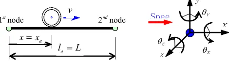
The bridge is modeled by means of three- dimensional two-nodded beam elements. Each node
has six degrees of freedom
T x y z x y z
u u u θ θ θ .
The element geometry and nodal sign conventions are depicted in Fig. 5. The shear deformation is disregarded in this study since the affection of shear deformation to the total girder deformation is small. Both normal beam (C0) and high-order beams (C1) in generalized coordinates are usedas displacement shape functions for axial directional DOFs and flexural DOFs, respectively.
At the current time or current position of the train, bridge elements are classified into two types by loading condition, i.e. loaded elements where the wheels are posited, and unloaded elements. Every wheel is therefore corresponding to an element.
x
θx y
Spee θy
θz z
v
e
l =L
e
x=x
[image:8.595.46.281.589.652.2]1 nodest 2 nodend
Fig 5. Loaded bridge beam element and sign conventions for displacements and nodal forces
The motion equation of the bridge structure is:
{FS(t)} is the nodal force vector applied into the bridge structure. The mass matrix MS can be lumped or consistent formulation as stiffness matrix using the same shape functions. The stiffness matrix KS of the bridge that is efficiently stored in one- dimensional array is assembled from element stiffness matrices. The damping matrix of bridge is obtained by making use of Rayleigh damping:
where the mass and stiffness proportional coefficients a0 and a1 are computed from fundamental frequencies i, j and modal damping ratios
i j
ξ
=
ξ
=
ξ
of the bridge. (Clough et al., 1993)3.1 Interpolation of wheel forces acting on bridge and nodal responses of bridge
The dynamic wheel forces acting on the bridge at location of the k-th wheel are then interpolated into the nodal forces of the corresponding element by the consistent shape functions used in the formulation of bridge beam element. For bridge modeled by high-order
beam elements (
{ }
1
C
shape functions), the wheel forces acting on bridge at wheel position are interpolated to nodal forces vectors of the first node and the second nodes
{ }
1 1 1 1 1 1 Te x y z x y z
i
F = F F F M M M , i=1,2 using
shape functions evaluated at x = xe. These element-wise nodal forces are then assembled to be the structure-wise nodal forces {FS(t)} shown in Eq. 16.
Since train-bridge dynamic interaction depends on
the responses of bridge
T x y z x y z e e e e e e
u u u θ θ θ at
0 0 1 2
1 2
1 2 e
x x x
T e
x x x x x
e
u u u
N N
θ θ θ =
⎧ ⎫ ⎡ ⎤
⎪ ⎪ =
⎨ ⎬ ⎢ ⎥
⎪ ⎪ ⎣ ⎦
⎩ ⎭ (19)
1 1 1 1 1 1 2 2
1 1 2 2
1 1 2 2 e
y y y y y
T e
z z z z z x x
e
u u u
N N N N
u u u
θ θ
θ θ =
⎧ ⎫ ⎡ ⎤
⎪ ⎪ =
⎨ ⎬ ⎢ ⎥
⎪ ⎪ ⎣ ⎦
⎩ ⎭ (20)
1 2 , 1 1 1 2 sin sin 2 v v njk N N v y nik R
n n
v v S v x x
A n x n x
IR S
N N L D
π π
= = =
⎡ ⎛ ⎞ ⎛ ⎞⎤ = ⎢ + ⎜ ⎟+ ⎜ ⎟⎥
+ + ⎣ ∑ ⎝ ⎠ ∑ ⎝ ⎠⎦ (22)
1 2 , 1 1 1 2 sin sin 2 h h njk N N h z nik R
n n
h h S h x x
A n x n x
IR S
N N L D
π π
= = =
⎡ ⎛ ⎞ ⎛ ⎞⎤ = + + ⎢ + ⎜ ⎟+ ⎜ ⎟⎥ ⎝ ⎠ ⎝ ⎠
⎣ ∑ ∑ ⎦ (23)
, 0 c yz nik g
r
IR
b
r
=
−
(24){ }
1 1 1 1 1 1 1 T e x y z x y zu = u u u θ θ θ and of the last node
{ }
2 2 2 2 2 2 2 T e x y z x y zu = u u u θ θ θ of the corresponding
element computed from finite element solution.
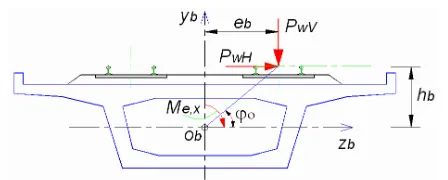
3.2 Eccentricity due to Double Track
Since the double track on the bridges for high- speed train is generally constructed, the analysis of considering the eccentricity of axle load caused by the train running is more reasonable. Therefore, beam element makes it available to consider the affectionwith eccentricity of axle load by including the parameters of eccentricity eb and hb that are the horizontal distance from vertical center line of the bridge section to vertical centerline of the track (or wheel-axle), and the vertical distance from neutral axis of bridge section to the upper rail surface level (or the deck level since the height of rail is negligibly small) respectively.
With the existence of both lateral and vertical wheel-rail contact forces PwH and PwV acting onto the bridge as shown in Fig. 6, the eccentric moment created is calculated as:
ex wV b wH b
[image:9.595.52.276.611.701.2]M
=
P e
+
P h
(21)Fig 6. Moment due to eccentric track
3.3 Generation of Track Irregularities
Track irregularities represent an important excitation source of bridge and train vibration during the passage of train. Frequencies of irregularity occurrence may match with bridge frequencies resultingin severe resonance. The irregularities consist of deviations of the inside and upper edges of the rail from ideal geometry. Four distinguishedtypes of irregularity can be generated; (1) Elevation irregularity (or vertical profile) IRy,nik which is the mean elevation of two rails, (2) Alignment irregularity IRz,nik which is the mean lateral position of two rails, (3) Cross-elevation irregularity (or cross level) rc, which is the differences in elevation of two rails, and (4) Gauge irregularity rg, which is the horizontal distance between the inside edges of two rails measured perpendicular to them 14 mm below the top of rails.
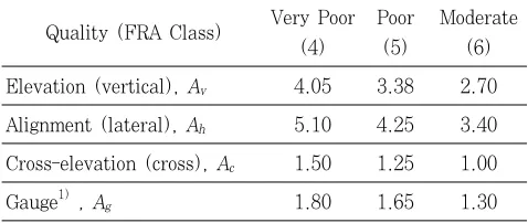
This study uses the proposed semi-periodic profiles in which irregularity amplitudes Av, Ah, Ac and Ag are maximum tolerable deviations according to FRA (Federal Railroad Administration, USA) in elevation, alignment, cross level and gauge irregularities shown in Table 1 (Yang et al., 2004), and the periodic coefficients are made related to total length of railway LT, rail bar length LR, sleeper step LS and distances between irregular micro-spots of rail in lateral and vertical directions Dh and Dv.
The angular irregularity of rail used in this study is computed as:
1 2
1 1
1 2
sin sin
2
c c
njk
N N
c
c R
n n
c c S v x x
A n x n x
r S
N N L D
π π
= = =
⎡ ⎛ ⎞ ⎛ ⎞⎤ = ⎢ + ⎜ ⎟+ ⎜ ⎟⎥
+ + ⎣ ∑ ⎝ ⎠ ∑ ⎝ ⎠⎦ (25)
,
z nik g g
h
IR
A
r
A
=
and (26)
sin
sin
R
T R
x
x
S
L
L
π
π
⎛
⎞
⎛
⎞
=
⎜
⎟
+
⎜
⎟
⎝
⎠
⎝
⎠
(27) [image:10.595.52.281.88.196.2]The irregularity profiles of rail generated in Eqs. (22-27) are evaluated at every position of wheel x = xnjk. Nv1, Nv2are the maximum number of sleeper steps and micro-spot distances in the wave lengths of vertical rail profile and their value are chosen basing on the condition of supporting ballast in vertical direction, typically in range (1-3) and must be less than LR/LS and LS/Dv respectively. The same definition is used for Nh1, Nh2 and Nc1, Nc2 in lateral and cross rail profiles.
Table 1. FRA Maximum Tolerable Deviations (Unit: mm)
Quality (FRA Class) Very Poor (4)
Poor (5)
Moderate (6) Elevation (vertical), Av 4.05 3.38 2.70
Alignment (lateral), Ah 5.10 4.25 3.40
Cross-elevation (cross), Ac 1.50 1.25 1.00
Gauge1) , Ag 1.80 1.65 1.30
4. SOLUTION FOR TRAIN- BRIDGE DYNAMIC
INTERACTION PROBLEM
The railway bridge and the high-speed train are considered as two separated structures interacting with each other only at time-dependent contact points between wheels and rail. The train’s motion equation (1) and bridge’s motion equation (15) are therefore coupled through interacting force vector
{
F t( )}
tr and{
F tS( )}
that all depend on thetime-dependent responses of wheels. Thus, a numerical integration method (Newmark-) with an
[image:10.595.43.282.422.523.2]iteration scheme whose algorithm shown in Fig. 7 is employed to solve. The magnitude of those interacting forces must be determined at the end of each time step. In every iteration step of the current time step, the previously-assumed and the newly-calculated displacements are compared until desired accuracy obtained.
Fig 7. Solution algorithm for bridge-train dynamic interaction
A computer program simulating 3-D train-bridge dynamic interaction and solving this problem by the new formulation presented above is implemented as a new module DM3-D of the multi-purposed finite element analysis software, XFINAS, developed in AIT and Konkuk University (Kim, 2007). Various element libraries and structural analysis solution are available in this software. The window menu of 3-D development of D train-bridge dynamic interaction is shown in the appendix.
5. NUMERICAL EXAMPLE
Fig 8. Profile of train and bridge
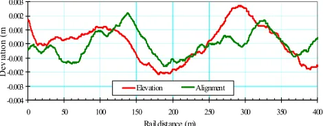
The semi-periodic profiles of rail irregularities proposed in section 3.3 are used with the irregularity amplitudes Av, Ah, Ac and Ag taken from Table 1, LT = 80 m, LR = 10 m, LS = 0.5m and Dh = Dv = 0.1 m. Three classes of rail irregularities, according to FRA as shown in Table 1, are considered in this bridge-train interaction analysis, namely, the very poor condition or class 4, moderate condition or class 6 according to FRA and non-irregularity condition. The generated profiles of a 400 meter-length section with rail quality class 6 are plotted in Fig. 9 for the elevation and alignment profiles and in Fig. 10 for the cross-elevation profile
-0.004 -0.003 -0.002 -0.001 0.000 0.001 0.002 0.003
0 50 100 150 200 250 300 350 400
Rail distance (m)
D
ev
ia
tion (
m
[image:11.595.48.283.453.545.2]Elevation Alignment
Fig 9. Generated elevation and alignment profiles of rail by proposed semi-periodic procedure, rail class 6
(moderate)
-0.002 -0.001 0.000 0.001 0.002
0 50 100 150 200 250 300 350 400
Rail distance (m)
R
ot
at
io
n (ra
d) Cross-elevation
Fig 10. Generated cross-elevation profile of rail by proposed semi-periodic procedure, rail class 6 (moderate)
The first two modal damping ratios of the bridge
are taken as
ξ
1=ξ
2=0.05. Using XFINAS program,the bridge is modeled by 16 three-dimensional two-nodded beam elements. The first three vibration periods of the bridge solved using subspace iteration method are: T1 = 0.65403sec., T2 = 0.16469 sec., and T3 = 0.15062 sec. Mass and stiffness-
proportional damping coefficients computed are a0=
0.76744 and a1= 0.002094.
The proposed formulation and analysis algorithm for 3-D dynamic interaction of articulated train-bridge is verified using the validated 2-D bridge-train interaction model (Kim et al., 2001). In this validated 2-D model, vertical displacement and pitching motion of the car bodyand the bogie and vertical displacement at the axle are considered as general coordinates for train modeling, Lagrange’s equation is used to derive the equation of motion of the train system and the bridge is modeled by means of two-dimensional beam element.
5.1 Bridge Responses
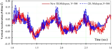
The time histories of bridge mid-span vertical displacements and accelerations at train speed of 300 km/h are plotted Fig. 11 and Fig. 12respectively. It is seen from those figures that the responses computed from the new 3-D bridge-train interaction model closely match with that of the validated 2-D model.
[image:11.595.45.281.456.692.2]4.0E-02 6.0E-02 8.0E-02 1.0E-01
50 75 100 125 150 175 200 225 250 275 300
Speed (km/h)
M
ax
. V
er
t A
cce
o
f T
rai
n (
[image:12.595.327.548.94.220.2]g) 2nd Car, Rail class 6 5th Car, Rail class 6
Fig 15. Max. vertical acceleration of 2nd car and 5th car vs. speed, rail class 6
mid-span lateral displacement, as shown in Fig. 14, also increases when the speed is rising from 5. *104 to about 2. *105m/h, largely dropfter speed reaches 2.5*105m/h. Between speed events 2.0*105 and 2.5*105m/h, there is a little reduce of mid-span lateral displacement.
-3.5E-02 -2.5E-02 -1.5E-02 -5.0E-03 5.0E-03 1.5E-02
0.0 1.0 2.0 3.0 4.0
Time (sec)
Ve
rt
ic
al
Di
sp
la
ce
m
en
t (
m
) New 3D,Mid span, V=300 2D, Mid span,V=300
Fig 11. Vertical displacements at mid-span of bridge at V=3.0*105m/h by the new 3-D bridge-train interaction
model and comparable 2-D model.
-0.15 -0.10 -0.05 0.00 0.05 0.10 0.15 0.20
1.0 1.5 2.0 2.5 3.0
Time (sec)
Vert
ic
al
A
ccel
er
at
io
n
(9
.8
1m
/s
[image:12.595.47.281.369.474.2]2) New 3D,Midspan, V=300 2D, Midspan,V=300
Fig 12. Vertical accelerations at mid-span of bridge at V=3.0*105m/h by new 3-D bridge-train interaction model
and the comparable 2-D model
1.8E-02 2.2E-02 2.6E-02 3.0E-02
50 75 100 125 150 175 200 225 250 275 300
Speed (km/h)
M
ax
. V
er
t D
is
p
of
M
id
span
(m
)
[image:12.595.52.287.548.672.2]Max Vert Disp Vs. Speed, Rail Class 6
Fig. 13. Max. vertical displacement at mid-span vs. speed, rail class 6
1.0E-04 1.2E-04 1.4E-04 1.6E-04
50 75 100 125 150 175 200 225 250 275 300
Speed (km/h)
M
ax.
L
at
. D
is
p o
f Mi
ds
p
an (
m
)
Max Lat Disp Vs. Speed, Rail Class 6
Fig 14. Max. lateral displacement at mid-span vs. speed, rail class 6
5.2 Train Responses
[image:12.595.317.546.575.695.2]1.0E-01 1.2E-01 1.4E-01 1.6E-01 1.8E-01
50 75 100 125 150 175 200 225 250 275 300
Speed (km/h)
M
ax
. La
t A
cc
e
o
f Tr
ai
n (
m
/s
2 ) 2nd Car, Rail class 6
5th Car, Rail class 6
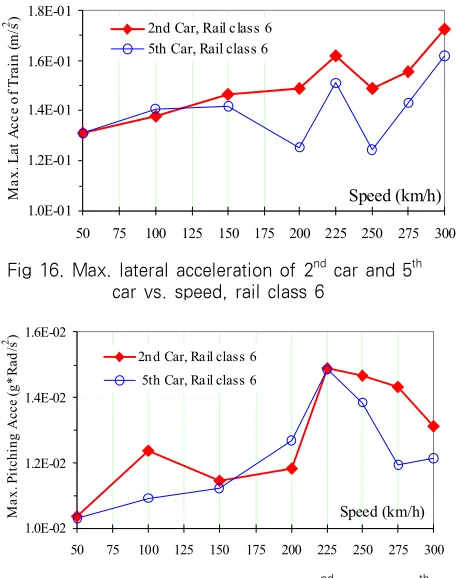
Fig 16. Max. lateral acceleration of 2nd car and 5th car vs. speed, rail class 6
1.0E-02 1.2E-02 1.4E-02 1.6E-02
50 75 100 125 150 175 200 225 250 275 300
Speed (km/h)
M
ax
. P
it
chi
ng
A
cce
(g
*
R
ad
/s
2 )
[image:13.595.50.279.92.381.2]2nd Car, Rail class 6 5th Car, Rail class 6
Fig 17. Max. pitching acceleration of 2nd car and 5th car vs. speed, rail class 6
5.0E-03 1.0E-02 1.5E-02 2.0E-02
50 75 100 125 150 175 200 225 250 275 300
Speed (km/h)
Ma
x
. L
at
D
isp
o
f
W
he
el
(
m
)
[image:13.595.48.277.429.555.2]1st W heel, Rail class 6 20th wheel, Rail class 6
Fig 18. Max. relative lateral displacement of 1st wheel and 20th wheel vs. speeds, rail class 6
6. CONCLUSIONS
The results from new 3-Dtrain-bridge interaction show good agreement with the comparable solution. This new 3-D train-bridge interaction analysis yields not only space responses of the bridge during train running, but also responses of the train, especially the vertical, lateral, rolling, pitching components of car-body acceleration those are essential to assess the riding comport of the train and the railway
system. The computation of lateral components of wheel relative displacement to bridge reveals capacity of this model that it be used to directly check for possible derailment sources of train operation dangers. When the train speed is increasing, a general tendency can be seen that both bridge responses and train responses also rise, proving a conclusion that the dynamic impact increases with train speed. Since the moving path of the train over the bridge is defined separately from the bridge, this bridge-train interaction model and dynamic analysis algorithm program is certainly applicable for complex structures such as multi- spanned, truss bridge, cable-stayed and suspended bridges.
ACKNOWLEDGEMENT
This paper was supported by Konkuk University in 2006.
APPENDIX A. DERIVATIONS OF THE MOTION
EQUATIONS
Consider the nth car-body, let it and the connected car-bodies and bogies undergo displacements in positive direction
{ } {
c c c c c c}
n n Xn Zn n Yn
u = Y R R Z R
{ } {
u
nb1=
Y R
nb1 bXn1R Z R
Znb1 nb1 Ynb1}
and{ } {
u
nb2=
Y R
nb2 bXn2R
Znb2Z R
nb2 Ynb2}
respectively. In succession of the equilibrium in each of five translational and rotational directions, the total forces (spring forces, damping forces, inertia and gravitational forces) acting into this car-body due to these displacements is equal to zero.Total forces in lateral direction
∑
F
Yc=
0
isexpanded as
(A2)
(A3)
(A4)
(A5) Total rolling moment about OX axis of the
car-body
∑
M
O Xc=
0
is expanded asTotal yawing moment about OZ axis of the
car-body
∑
M
O ZC=
0
is expanded asTotal forces in vertical direction
∑
F
Zc=
0
isexpanded as
Total pitching moment about OY axis of the car
body
∑
M
O Yc=
0
is expressed asAPENDIX 2: Three-Dimensional Analysis of Bridge -Train Dynamic Interaction (KTX, TGV, ICE/ Shinkansen)
[image:14.595.311.553.86.189.2]Fig 19. KTX/ TGV in Korea and France
Fig 20. ICE in Germany, Shinkansen in Japan and the Taiwan high-speed train
그림 21. KTX 고속철도교량의 3차원 동적 해석 결과
REFERENCES
Bathe, K.J.(1996) Finite Element Procedures: Prentice Hall, New Jersey.
Clough, R.W. and Penzien, J.(1993) Dynamics of Structures, McGraw-Hill, Singapore.
Frýba L.(1996) Dynamics of Railways Bridges. Thomas Telford, London, England
Frýba Ladislav(1999) Vibration of Solids and Structures under Moving Loads. Thomas Telford, London, England.
Kim, M.C., Chung, W.J., and Kang, K.D.(2001) Performance Evaluation of KHSR Bridge using Two-Dimensional Train/Track/Bridge Interaction Analysis Method. Korea Railroad Research Institute Report. Republic of Korea.
Kim, K.D.(2007) XFINAS Theory Manual 3.0, www.xfinas.com.
Kwark J.W., Choi E.S., Kim Y.j., Kim B.S., Kim S.I.(2004) Dynamic behavior of two-span continuous concrete bridges under moving high-speed train. Computers and Structures 82, pp.463-474.
[image:14.595.43.284.600.700.2]Volume 3, pp.369-374.
Nguyen, D.V., Kim, K.D., Warnitchai, P., and Duc, D.M.(2006) Evaluation of Passenger Ride Comfort, Noise and Operation Safety of Elevated High- speed Trains. Proceedings of The 12th International Student Seminar on Transport Research Symposium (ISSOT-12), Bangkok, Thailand. pp.166-175. Song M. K., Noh H.C., and Choi C.K.(2003) A new
three-dimensional finite element analysis model of high-speed train–bridge interactions. Engineering Structures. 25. pp.1611-1626.
Xia, H., Xu, Y.L., and Chan, T.H.T(2000) Dynamic Interaction of Long Suspension Bridges with Running Train. Journal of Sound and Vibration
237(2). pp.263-280.
Yang, C. F.(1986) Random Vibration of Structures. John Willey & Sons. Canada.
Yang Y.B., Yau J.D., and Wu Y.S.(2004) Vehicle-Bridge Interaction Dynamics: with Applications to High- Speed Railways. World Scientific Publishing Co. Pte. Ltd.
Yang, F., and Fonder, G.A.(1996) An Iterative Solution Method for Dynamic Response of Bridge-Vehicle System. Earthquake Engineering and Structural Dynamics V 25. pp.195-215.