BUILD A
Other TAB Electronics Robotics Titles
The Robot Builder’s Bonanza, Second Edition, by Gordon McComb
Robots, Androids, and Animatrons, Second Edition, by John Iovine
McGraw-Hill
New York • Chicago • San Francisco • Lisbon • London • Madrid Mexico City • Milan • New Delhi • San Juan • Seoul
Singapore • Sydney • Toronto
BUILD A
REMOTE-CONTROLLED
ROBOT
Copyright © 2002 by The McGraw-Hill Companies, Inc. All rights reserved. Manufactured in the United States of America. Except as permitted under the United States Copyright Act of 1976, no part of this publication may be reproduced or distributed in any form or by any means, or stored in a data-base or retrieval system, without the prior written permission of the publisher.
0-07-140964-5
The material in this eBook also appears in the print version of this title: 0-07-138543-6
All trademarks are trademarks of their respective owners. Rather than put a trademark symbol after every occurrence of a trademarked name, we use names in an editorial fashion only, and to the benefit of the trademark owner, with no intention of infringement of the trademark. Where such designations appear in this book, they have been printed with initial caps.
McGraw-Hill eBooks are available at special quantity discounts to use as premiums and sales pro-motions, or for use in corporate training programs. For more information, please contact George Hoare, Special Sales, at [email protected] or (212) 904-4069.
TERMS OF USE
This is a copyrighted work and The McGraw-Hill Companies, Inc. (“McGraw-Hill”) and its licensors reserve all rights in and to the work. Use of this work is subject to these terms. Except as permitted under the Copyright Act of 1976 and the right to store and retrieve one copy of the work, you may not decompile, disassemble, reverse engineer, reproduce, modify, create derivative works based upon, transmit, distribute, disseminate, sell, publish or sublicense the work or any part of it without McGraw-Hill’s prior consent. You may use the work for your own noncommercial and personal use; any other use of the work is strictly prohibited. Your right to use the work may be terminated if you fail to comply with these terms.
THE WORK IS PROVIDED “AS IS”. McGRAW-HILL AND ITS LICENSORS MAKE NO GUAR-ANTEES OR WARRANTIES AS TO THE ACCURACY, ADEQUACY OR COMPLETENESS OF OR RESULTS TO BE OBTAINED FROM USING THE WORK, INCLUDING ANY INFORMA-TION THAT CAN BE ACCESSED THROUGH THE WORK VIA HYPERLINK OR OTHERWISE, AND EXPRESSLY DISCLAIM ANY WARRANTY, EXPRESS OR IMPLIED, INCLUDING BUT NOT LIMITED TO IMPLIED WARRANTIES OF MERCHANTABILITY OR FITNESS FOR A PARTICULAR PURPOSE. McGraw-Hill and its licensors do not warrant or guarantee that the func-tions contained in the work will meet your requirements or that its operation will be uninterrupted or error free. Neither McGraw-Hill nor its licensors shall be liable to you or anyone else for any inac-curacy, error or omission, regardless of cause, in the work or for any damages resulting therefrom. McGraw-Hill has no responsibility for the content of any information accessed through the work. Under no circumstances shall McGraw-Hill and/or its licensors be liable for any indirect, incidental, special, punitive, consequential or similar damages that result from the use of or inability to use the work, even if any of them has been advised of the possibility of such damages. This limitation of lia-bility shall apply to any claim or cause whatsoever whether such claim or cause arises in contract, tort or otherwise.
DOI: 10.1036/0071409645
abc
ABOUT THE AUTHOR
David Shircliff is a teacher at Seneca Ridge Middle School in Loudon County, Virginia, where he teaches classes in technology education. A dedicated electronics enthusiast, Mr. Shircliff has been researching and building robots for over 20 years.
vii
CONTENTS
Preface ix
Introduction xi
CHAPTER ONE. THE MOTORIZED PLATFORM 1
Preparing Motorized Wheels 1
The Platform 4
Mounting Wheels 6
Third Castor Wheel 9
Finishing Touches 11
CHAPTER TWO. BODY FRAMEWORK 13
Cutting Aluminum 13
Drilling and Cutting the Sections 15
Assembling Framework 30
Mounting Framework on the Platform 34
Mounting the Vacuum Outlet 35
CHAPTER THREE. POWER SUPPLY AND
TEMPORARY CONTROL BOX 39
Mounting Batteries and Barrier Strips 39
Wiring Platform 43
Temporary Control Box 45
Control Box Construction 48
Wiring the Temporary Control Box 48
Using the Control Box 51
Copyright 2002 The McGraw-Hill Companies, Inc. Click Here for Terms of Use.
CHAPTER FOUR. REMOTE CONTROL SYSTEM 53
Motherboard 57
Wiring the Motherboard 60
Completing the Motherboard 62
Installing and Wiring the Motherboard 63
Using the Remote Control System 66
CHAPTER FIVE. ARMS AND SUBSYSTEMS 67
Arms 69
Drink Dispenser 75
The Head 80
Wiring the Vacuum System 81
CHAPTER SIX. SKIN AND FINISHING TOUCHES 85
Skin 85
Mounting Tray 91
Mounting Controls 92
Body Lights and Horn 96
12-Volt Power Outlet 98
Bow Tie 98
Painting and Trimming the Body 100
Trim 100
Sources 107
Index 111
PREFACE
I
n recent years robots have captured the interest of more and more people. Thanks to movies and TV, the notion of the robot as a mechanical companion and servant has become a common concept. As interest in robots grew, a number of books showing how to build robots at home began to appear. These books, however, were very technical, showing how to build computer-controlled mobile platforms that are consid-ered by most to be true robots.My interest in robots leaned more toward the popular con-cept of robots as humanlike friends and servants. I did not have the technical skill or funds to build a computer-controlled robot, so I decided to develop a robot that would fit the popu-lar image of robots and not be too difficult to complete or expensive to build. The result was Questor.
While working on Questor, I tried to develop a project that I, as a beginner, could complete with little technical skill, using tools I had in my workshop. Also, I wanted Questor to look and function like a robot butler, a form I felt best fit the friend/servant theme. For this reason I needed a people-sized robot that would have great presence. I concentrated more on form than sophistication to develop an impressive looking, but relatively simple-to-build, project—a beginner’s project.
Later, when I decided to write a book about the project, I wanted to avoid weaknesses I found in other how-to robot books. This book is heavily illustrated, helping to take the guesswork out of Questor’s construction. Next, the book deals only with the construction of the robot, and not the theories on which it is based. This type of information is best derived from specialty electronics and robotics books. I have included
ix
a list of books and magazines that supply information, as well as other possible sources for robot kits and parts.
It is my hope that you will use this book not only to build your own version of Questor, but to guide you in creating your own unique robot. This way your robot will reflect your knowl-edge and skill as a builder. Also, I hope that your robot will be used as a test bed for other robotics projects. If you are like me, once you build your own robot, you’ll always be trying to improve it.
David R. Shircliff
INTRODUCTION
O
ne of the first questions you will have to answer when you say you have your own robot is, “What does it do?” If your answer (as mine) is, “It rolls around by remote control and serves drinks” disappoints the questioner, don’t be offended. It simply means that the person asking the question knows little about the real world of robotics, the science of robots.Before you can attempt to explain your answer to the unin-formed asker, you must know a little about the subject of robots. Ask yourself, “What is a robot?” The word robot comes from the Czech word Robota, which means obligatory work or servitude. The word robot was first used in a Czech play called
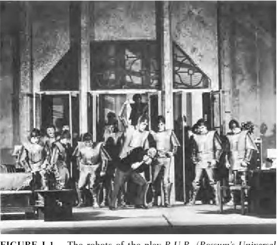
R.U.R. (Rossum’s Universal Robots) by Karl Capek. Written in
1921, the play depicts a race of humanoid robots that turn on their masters and destroy them, a theme that seems always to be associated with robots. Figure I-1 shows a scene from the play.
The exact meaning of the term robot, even in today’s techno-logical age, is a matter of debate. Man’s technical prowess makes the exact meaning elusive: manlike mechanical device; person working mechanically, without original thought; machine or device that works automatically. These definitions seem rather broad and could encompass any number of modern devices from a dishwasher to a timer-controlled video cassette recorder, with-out conjuring up the popular Star Warsnotion of robots.
A second, more-precise definition is stated by the Robot Institute of America. It reads: “A robot is a programmable mul-tifunctional manipulator designed to move material, parts, tools or specialized devices through variable programmed motions for the performance of a variety of tasks.”
While more precise, it tends to be narrow and also does not parallel the popular notion of the mechanical friend everyone
xi
would like to have. It applies more specifically to those types of robots at work in factories all over the world, shown here in Figs. I-2 through I-4. These assembly line type robots can do everything from welding a car (then painting it) to assembling delicate electronics components, all automatically, 24 hours a day if needed, and without a break. They don’t get sick (although when they do break down, they can be easily repaired or even replaced), ask for pay raises, or any pay for that matter, and can be retrained to do another job in a matter of minutes by simply changing the job program in their control computers. If you look again at Figs. I-2 through I-4, you will see that while the device most certainly looks mechanical, it does not look like a human. Instead it takes the shape of the most useful part of the human anatomy, from a robot stand-point, the arm.
Both these definitions seem to be correct in their specific case, but there is a middle family between the simple auto-mated device and the sophisticated computer-controlled
[image:13.432.54.336.62.310.2]xii INTRODUCTION
manipulator. This middle family is that of the show robot or showbot. Questor, the robot outlined in this book, is a mem-ber of the showbot family. Figures I-5 through I-8 picture examples of commercial show robots.
A showbot in most cases has no computer brain. Instead it is controlled via a remote control system operated by a person somewhere out of sight. You might have seen or heard of a
[image:14.432.54.381.63.471.2]INTRODUCTION xiii
xiv INTRODUCTION
FIGURE I-3. Robots are best used for repetitive tasks like stacking. (Courtesy of Unimation Inc.)
showbot entertaining groups of fascinated people in shopping malls or on TV as characters in movies. I even read about a showbot delivering a speech at a college graduation. Showbots, however, can be adapted for use in the home.
This book lays the groundwork to construct one such home showbot, Questor. (See Figs. I-9 and I-10.) Questor was designed to look like and function like a butler. There is a drink dispenser built into his arm and a vacuum port in his mobile platform. I felt these two functions are what most people expect a robot servant to do. The arms, which help promote Questor’s humanoid shape, are nonfunctional; they serve only to hold the serving tray. The hands are made of two auto drink holders. A button located on the wrist (the area above where the hands are bolted on) controls the drink dispenser.
His head is a lamp, and there are two headlights on the front of the mobile platform. These lights not only help the operator guide the showbot at night, but they are very useful during power blackouts. There is also a 12-volt direct current (dc) ciga-rette lighter plug on the side of the base. This is used to run bat-tery-powered appliances such as portable radios or TVs off the robot’s batteries.
INTRODUCTION xv
A horn located on the lower part of the front body panel announces Questor’s presence. I plan to add a tape recorder for prerecorded messages. This is something you could consider designing into your showbot. Finally, his body panels and arms were painted to look as though Questor is wearing a tuxedo jacket, and a light-up bow tie completes the look.
I also designed Questor so he could be built using tools found in a home workshop and parts available in local hard-ware and electronics stores. However, there are a few parts you will have to order. The following list of what I’ve deter-mined are “must buy parts” shows items you will need to pur-chase before starting construction. The address for a parts supplier, Herbach & Rademan Company, is listed in Sources in the back of the book.
xvi INTRODUCTION
Must Buy Parts
2 12-volt dc motorized wheels
2 6-volt, 8-amp solid gel batteries, with charge kit 2 10-ohm, 25-watt potentiometers
Note: The drink dispenser motor and vacuum system kit can also be ordered from Herbach & Rademan. The rest of the parts needed for each phase of Questor’s construction will be listed in the beginning of each chapter.
All of Questor’s various components, except for the remote control system, are powered by a 12-volt dc battery system. Questor can be controlled by either a control box connected to the base by a cable or a wireless remote control system. The
INTRODUCTION xvii
remote control system, as are the rest of the parts, is a standard off-the-shelf item.
At this point, you should read through the book to famil-iarize yourself with the diagrams, photographs, parts lists, and overall format. Once you plan your showbot, you can order the “must buy” items. You are now ready to enter the fascinat-ing world of robotics.
ROBOT BASICS
But first, a review of the basics.
The construction of a remote-controlled robot, while not easy, need not be difficult. My motto when designing and building Questor was “keep it simple, stupid” (KISS)! The
xviii INTRODUCTION
INTRODUCTION xix
FIGURE I-9. Questor the robot servant (front view).
best strategy is to use as many off-the-shelf items as possible. As your confidence and skill level grow, you can design and build your own components. In addition, as you work with different materials, such as wood, plastic, and metal, you will learn the properties of each and how you can use them in your own robot designs.
When I first started to design and build remote-controlled robots I used a very simple motorized wheel assembly taken out of a toy car and made bodies out of poster board and con-struction paper. Figure I-11 shows the plans for one such robot. I tried to make these robots life size, 3 to 4 feet tall. They were fun to design and build and taught me a lot about what would work without being expensive to construct. If you are a first-time robot builder, I suggest that you try one of these paper robots. Whether made of paper or wood and metal, all my robot designs have four basic subsystems: a motorized base, a remote control system, a power supply, and a body.
M
OTORIZEDB
ASEThe motorized base for your robot can be the most difficult subsystem to design and build. You can save yourself a lot of trouble if you design “around” this part of the robot. Instead of designing the robot first and fitting the motorized base to your design, design and build the base first and then fit your robot body to it. The base generally holds all of the internal parts or “guts” that make your robot work. In Questor, for example, the base has the wheels mounted on it as well as the batteries (which can be quite heavy) and the control system. That is why he looks the way he does. The old saying “form follows function” is true in robot design, too.
The most important part of the base is the motor-driven wheels. This is where many (myself included) robot builders have the most problems. Do yourself a favor and buy motor-ized wheel units. A supplier is listed in the back of the book. These units already have a motor mounted to a drive wheel and usually the assembly is in a frame you can modify to attach to your base. With Questor’s motorized wheels all I had to do was design a way to mount them to the base. Figure I-12
shows the wheels I used for Questor. Another good source for motorized wheels is children’s ride-on toys. They already have the motors and wheels mounted to a frame (as well as the bat-teries) and can be used as is, or removed and mounted on your robot base. The main drawback of using ride-on toys is they lack a steering system. This is a critical area that you must design into your base.
INTRODUCTION xxi
3 cardboard supports
Base Arm
3/4" dowel Cup
C. B.
Motorized base
18"
A. Body
Head
There are several ways to set up a steering system for your robot. A robot must have a minimum of three wheels in order to work, and how you power and mount the wheels will affect your control of the robot. Figure I-13 shows the combinations available. All the combinations require two motorized wheels and at least one swiveling wheel for balance. This was the sys-tem I used in Questor. By making one motorized wheel go for-ward or in reverse, while the other is off or going forfor-ward, you can very effectively steer a robot. Table I-1 charts the combi-nations for steering with this system. All this “control” is pro-vided by the next subsystem, the remote control system.
R
EMOTEC
ONTROLS
YSTEMThe ability to remotely control your robot is a big part of its appeal. The two types of remote control are wiredand wireless. Basically, what you are doing with either system is tripping switches to control robot functions. Figure I-14 shows the two systems, as used for Questor.
xxii INTRODUCTION
With a wired remote control system the operator uses a control box connected to the robot via a long wire or cable. The advantages of this system are that it is simple to build and costs little to construct. The main disadvantages are limited range and the cable itself can get in the way. For the beginning robot builder, however, this is the best system to start out with. It will allow you to build and test systems for your robot with-out the complexity and expense of a wireless system.
Wireless remote control is what most people think of when you say “remote control.” A wireless system allows a much greater range for the operator, and there is no control cable to get in the way. A wireless system has three main parts. The
INTRODUCTION xxiii
Front drive Center drive
Drive wheel
Castor
Rear drive
FIGURE I-13. Drive wheel layouts.
TABLEI-1. Control Combinations MOTORIZED MOTORIZED ROBOT
WHEELONE WHEELTWO DIRECTION
On On Forward
Off Off Stop
On Off Right turn
Off On Left turn
On Reverse Spin right
first is a transmitter. This is what you will use to control your robot. The transmitter sends signals to a receiver. The receiver is the second part of the system; it uses the signals to control servos, the third part of the system. A servo takes decoded sig-nals from the receiver and uses them to turn a motor. Figure I-15 shows a complete wireless system. Systems like this one are readily available from your local hobby shop. The motor in a servo is very powerful for its size and can be used to trip switches within your robot and control it. Figure I-16 shows the servo/switch control system.
P
OWERS
UPPLYHow to power a robot is another area where the beginning robot builder can experience difficulty. Here my KISS philoso-phy can again help. You will find, as I did, that different systems have different power needs. The use of rechargeable batteries to power each of these systems is the simplest solution.
Question uses four rechargeable batteries. Two are 6-volt batteries wired together to supply the 12 volts needed to power the drive wheels, main lights, and vacuum cleaner. The
xxiv INTRODUCTION
other two batteries are both 9 volts. One powers the receiver used in the remote control system, while the other is used to power the robot’s blinking-light bow tie.
The 6-volt batteries came from a motorized children’s ride-on toy. They have the advantages of being readily available and being designed to be safe, because they are sealed. Another advantage is that the battery charger and plug needed come with the batteries (Fig. I-17). Currently you can find these batteries in both 6- and 12-volt sizes. The first of the 9-volt batteries came with the remote control system along with a charger for both the receiver and the transmitter. The second 9-volt battery, for the blinking bow tie, is simply a standard rechargeable. Figure I-18 shows the two 9-volt batteries. You will notice that while they are both 9 volts they are different sizes.
By using separate batteries for each system you can avoid having to build the complex circuits needed to raise or lower
INTRODUCTION xxv
xxvi INTRODUCTION
FIGURE I-17. Battery from children’s ride-on toy.
battery power. However, if you have many systems on your robot (for example, two or three blinking lights) you will have to recharge a lot of batteries. You can, though, combine sys-tems with the same power needs to feed off the same battery.
Regardless of how many batteries you use, you will have to be able to access them, as well as the other subsystems of your robot. This brings us to the next and, for a showbot, the most important subsystem: the body.
B
ODYA robot’s body tells the world who the robot is and what it can do. For a show robot the body is its reason for existence, because showbots are used for entertainment and to help advertise products. Questor was designed to be a robot butler. He has a waiter’s jacket painted on his body panels, and his arms, while nonfunctional, do hold a serving tray. A blinking bow tie helps complete his servant look. I built his body from scratch, after completing his motorized base, with this specific look in mind.
I am sure that you already have many ideas on how you would like your robot to look. I hope the examples given here will help spark your imagination. You should keep sketches of your robot ideas in a notebook, so as your skill level grows you can attempt your more advanced notions.
INTRODUCTION xxvii
One of the key points to keep in mind while designing is, what will you build your robot out of? For the beginning robot builder this can be particularly vital. What materials are you familiar with? Do you have the tools to work with a certain type of material? How much does a material cost? How much will the body weigh when complete? All these are questions that you will have to ask yourself. You can answer most of these questions if you use a body that is already built. Where can you get a prebuilt robot body? At your local variety store they are called trashcans! Before you shudder at the idea that your robot be made out of a trashcan, let us examine the advantages.
The main advantage of using a trashcan is that it is a ready-made container that can be built on. Take for an exam-ple a small metal garbage can, like that in Fig. I-19. Being metal (galvanized steel), it is very sturdy and has the added benefit of looking “robotic.” Even though it is made of metal it can be easily cut and drilled. (Care should be taken when
xxviii INTRODUCTION
working with metal because cutting and drilling will produce sharp edges.) The trashcan’s size is also of benefit because it helps your design have a “life-sized” look that is important to showbots. Figure I-20 pictures a showbot with a body the shape of a trashcan. If you feel that metal is too difficult to work with, simply buy a plastic trashcan. Be sure that the plastic is hard and nonflexible. Flexible plastic is weak and therefore makes a poor body.
Small metal cans, wash tubs, and even salad bowls can be used for robot bodies. Once your base is done you can experi-ment with different containers until a final design is reached. Figures I-21 and I-22 on pp. xxx and xxxi show sketches of two robot bodies. Notice how by stacking different containers, two very familiar (and famous) robots come to life.
I hope that this section on robot basics has prepared you for the fun you will encounter in the rest of the book.
INTRODUCTION xxix
xxx
FIGURE I-21.
Can you name this robot? (
Courtesy of
American Robots.
xxxi
FIGURE I-22.
Does this alternate head design look familiar? (
Courtesy of
American Robots.
THE MOTORIZED
PLATFORM
T
he motorized platform is a most important part ofQuestor’s construction. It not only supplies the robot with mobility, but contributes to its personality and appeal. Although simple in construction, the platform outlined in this chapter is capable of carrying 50 pounds of robot. To start its construction, the first job to perform is to prepare the motor-ized wheels that propel the platform.
PREPARING MOTORIZED WHEELS
Once you have obtained the motorized wheels, study them and learn how they operate and how they are assembled. This is important because you must disassemble the wheels in order to prepare them for attachment to the platform. Be careful not to lose any of the smaller parts and work on only one wheel at a time. Figures 1-1 and 1-2 show an assembled and disassembled wheel.
To disassemble the wheel, first remove the motor and gear-box assembly held to the side of the wheel’s frame by three small screws. On the opposite side of the frame is a cotter pin that holds the wheel’s axle and frame together. Remove this pin (this is done easily with a pair of needle nose pliers) and pull the axle out from the other side slowly. As you pull the axle out, four small spacing washers, two red plastic and two metal, will fall from the frame along with the wheel itself and the wheel’s large white driver gear.
1
C H A P T E R
O N E
Next remove the swivel ring from the top of the now bare frame. The ring is held in place by a cotter pin that passes through the large post on the top of the frame. Remove this pin and slide the swivel ring up the post and off the frame. There will be some grease and a small ball bearing left on the top of the frame. Wipe away the grease and remove the ball bearing. The swivel ring, cotter pin, and ball bearing are no longer needed for this robot, but add them to your parts sup-ply for later projects.
Now you are ready to prepare the empty frame for attach-ment to the platform. After considering many different meth-ods of attaching the wheels to the platform, I came to the conclusion that the most direct and simple way is to drill holes in the frame and holes in the platform, then bolt them together. Figure 1-3 shows the location of four 3-inch 1/4-inch-diameter holes that are to be drilled on the top of the frame. If you have never worked with metal before or do not
2 CHAPTERONE
have a strong vise, don’t attempt to drill the holes yourself. A local metal shop or school industrial arts class could do it for you.
Using Fig. 1-3, mark the locations of the holes on the top of the frame and start the holes with a center punch. This device makes a small dent in the metal for the drill bit to sit in. If you don’t have a center punch, a nail will do. I found the easiest way to drill the holes was using a strong vise, clamp one leg of the frame lengthwise between two pieces of wood. You will have to bend the legs apart slightly to accom-plish this. Now drill the hole marked on the top of the frame on the side of the leg that you clamped. After drilling,
THEMOTORIZEDPLATFORM 3
unclamp the leg, flip the frame over, clamp the other leg, and drill the hole on that side. Figure 1-4 shows how to clamp and drill the holes in this way. You could have clamped the frame posts in the vise, but round objects tend to slip when you drill them.
Now reassemble the first motorized wheel and disassemble and drill the second. Figure 1-5 shows the top view of one completed wheel. With both wheels drilled and assembled, it is time to cut and drill the platform.
THE PLATFORM
The platform itself is simply a 20- 20- 1/4-inch piece of plywood, cut from a larger 24- 24- 1/4-inch piece. While simple in design and construction, it is the key element on which all of Questor is mounted. Great care should be taken to try to keep all of the various holes and cuts as precise and as straight as possible. The easiest way to assure straight cuts is to measure 4 inches in from the bottom edge of one side of the board and 4 inches in from the top edge of the same side, then connect the two points with a line. Figure 1-6 shows how
4 CHAPTERONE
THEMOTORIZEDPLATFORM 5
FIGURE 1-4. Suggested clamping method.
to mark the plywood for cutting. After you cut the platform from the stock plywood, sand the cut edges to remove any splinters. Save the leftover plywood; it will be used later.
To mount the motorized wheels on the platform you must first drill two 3/4-inch-diameter holes to accommodate the posts of the wheel frame. Figure 1-7 shows where on the plat-form to drill the holes. If you don’t have access to a 3/4-inch-diameter drill bit, you can make the holes by drilling smaller holes around the inside of the 3/4-inch circle, then removing the wood with a coping saw. This rough circle is then filled and sanded to shape.
MOUNTING WHEELS
After the holes are drilled, it is time to mount the motorized wheels. To do this take one of the predrilled motorized
6 CHAPTERONE
wheels and insert its frame post into one of the 3/4-inch holes in the platform. Then turn the wheel so that the motor and gearbox face the center of the platform. Figure 1-8 shows the correct position of the wheels. You must make sure that the wheels point as straight as possible during the mounting process.
Each of the motorized wheels is held to the platform by four 2-inch 1/4-inch-diameter bolts. With the wheel point-ing as straight as possible, take a pencil and carefully mark the location of one of the four mounting holes in the wheel’s frame on the platform. Remove the motorized wheel and drill a 1/4-inch-diameter hole where marked. Now replace the wheel and realign the hole in the frame with the hole now in the platform. Take one of the eight bolts and insert it through the wheel’s frame and out the top of the platform. If the bolt does not go through the hole in the platform easily or after it’s inserted the motorized wheel is no longer straight, remove the wheel and redrill the hole in the platform slightly larger. The play in the hole will allow you to shift the wheel’s position.
THEMOTORIZEDPLATFORM 7
This, however, only works for small adjustments. With the bolt inserted you can now mark and drill the other holes starting with the hole in the opposite corner from the bolt. (If you started with the bottom left hole, drill the upper right next.) This method and order of marking and drilling helps ensure the wheels will be straight.
The motorized wheels’ final attachment to the platform is illustrated in Fig. 1-9. Notice the use of lockwashers. These washers are very important because they keep the nuts from coming loose due to vibration caused when the robot travels over rough surfaces. You should use lockwashers throughout your robot. Also Fig. 1-9 shows the use of a large bore washer. This washer should be approximately 2 inches in diameter with a 3/4-inch bore to allow it to slip over the post of the motorized wheel. The washer keeps a ridge on the top of the wheels’ frame from digging into the wooden platform when the bolts are tightened. Also, the washer helps keep the wheel sitting level. After the wheels are attached, make a final check to see that they are straight. Once the two motorized wheels are mounted, it is necessary to mount a third castor wheel on the front of the platform.
8 CHAPTERONE
THIRD CASTOR WHEEL
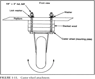
The castor wheel makes the platform level and gives it stability. The wheel should be about 3 inches in diameter and designed for heavy-duty use. Depending on the wheel you obtain, you’ll probably have to stack pieces of plywood between the platform and the mounting plate of the castor wheel so that the plat-form sits level. Figure 1-10 shows where on the platplat-form the wheel is mounted. Remember to make sure that the castor is centered along the front edge of the platform. A guideline shown in Fig. 1-10 shows how to do this.
After you find the center point, place the castor wheel on the platform so that if turned in a circle, the wheel will not pro-trude past the front edge of the platform. Next mark and drill the hole for the wheel’s mounting plate. (The diameter of the
THEMOTORIZEDPLATFORM 9
10 CHAPTERONE
TABLE1-1. Parts List
AMOUNT ITEM
2 Motorized wheel
1 Sheet of 24- 24- 1/4-inch plywood 1 4-inch-diameter castor wheel
8 2-inch 1/4-inch-diameter bolt, nut, and lockwasher set 4 3-inch 1/4-inch-diameter bolt, nut, and lockwasher set 2 2-inch 3/4-inch-diameter bore washer
1 Auto fiberglass repair kit, including cloth and resin 1 Can spray paint (color of your choice)
holes depends on the wheel you have obtained.) As I noted before, you will probably have to stack some plywood spacers (use the wood left over from when you made the platform) between the wheel and the platform. These spacers are made by tracing around the castor’s mounting plate and then marking and drilling the mounting holes as you did for the platform. When you stack the spacers, all the holes should line up.
Bolt the castor wheel and spacers to the platform as shown in Fig. 1-11. Then using a small level, check to see that the platform sits correctly. If the level of the platform is slightly off, this can be corrected by placing washers between the stacked plywood and the mounting plate of the castor until level.
FINISHING TOUCHES
After you have mounted all three wheels, remove them and paint the platform. This not only makes the platform look
[image:44.432.56.379.63.331.2]bet-THEMOTORIZEDPLATFORM 11
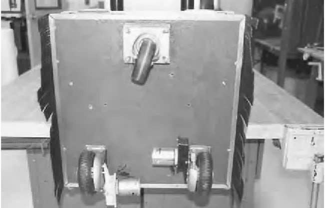
ter, but makes it water resistant. You may opt as I have to fiberglass the platform. Fiberglass also provides water protec-tion and adds strength to the platform. Fiberglass is very easy to work with (especially on a flat surface) so if you follow the directions on the package, you should have no problems. If you do use fiberglass, use a kit with a clear resin so you can locate and redrill all the mounting holes in the platform. Once you have fiberglassed and painted, you can reattach the three wheels. Figure 1-12 shows the completed platform.
[image:45.432.53.379.63.271.2]12 CHAPTERONE
BODY FRAMEWORK
Q
uestor’s body is made from five 8-foot1-inch 1-inch 1/8-inch strips of aluminum angle. I chose this material over wood or plastic because while slightly more expensive, it is stronger and more lightweight. Also, if care is taken, alu-minum is relatively easy to work with. The alualu-minum angle is used to form two boxes. These boxes are called the upper framework and the lower framework. Once joined, they make up Questor’s body.Before the boxes are constructed each section of alu-minum angle used to make up that portion of the body is marked and drilled with holes to be used later in the robot’s construction. These predrilled holes are best made when the framework is in pieces rather than when assembled. A chart will list how to assemble each box so all the predrilled holes are in their proper locations when the framework is complete. Remember to take your time and not to cut or drill the alu-minum angle until you have checked your measurements or hole locations against the book.
CUTTING ALUMINUM
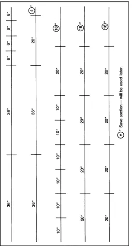
Figure 2-1 shows how to cut each of the five aluminum strips into the pieces that make up Questor’s framework. Cut the strips with a hack saw and use a miter box to achieve straight cuts. Be careful not to cut the aluminum before you have checked your measurements.
13
C H A P T E R
T W O
FIGURE 2-1.
Aluminum angle cutting guide.
Once you have cut the strips into pieces, separate them so that you have four 36-inch, four 6-inch, six 10-inch, and ten 20-inch pieces. Keep all the extra aluminum for use later.
Now that you have the various pieces grouped together, check to see if they are all the same length. If the pieces are slightly unequal, simply choose the shortest piece of that group and cut or file the others down to match it. After all the pieces have been grouped and trimmed, they must be predrilled and some pieces precut before assembly. This preparation will save you a lot of time and trouble later.
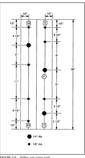
DRILLING AND CUTTING THE SECTIONS
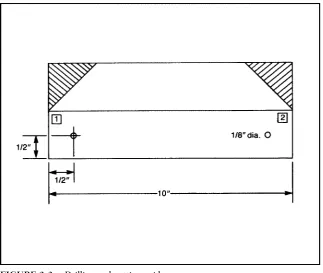
Many of the holes to be drilled now are not utilized until later in the robot’s construction. It is much easier to drill them now while the framework is in pieces than later when it is assem-bled. All the cuts to be made consist of 45-degree angles. These cuts are at the ends of one side of some of the pieces and allow them to be joined into squares with no overlap. Figure 2-2 shows an example of this.
Figures 2-3 through 2-26 illustrate how each piece of alu-minum is drilled or cut. Each figure consists of two rectan-gles; one rectangle represents each of the outer surfaces of
BODYFRAMEWORK 15
TABLE2-1. Parts List
AMOUNT ITEM
5 8-foot 1-inch 1-inch 1/8-inch angle aluminum 50 1/8-inch pop rivet (and rivet gun)
8 1-inch 5/32-inch-diameter bolt, nut, and lockwasher set
6 1-inch 1/4-inch-diameter bolt, nut, and lockwasher set
FIGURE 2-2. Angles cut so pieces can be joined at corners.
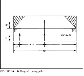
[image:49.432.54.378.322.595.2]FIGURE 2-4. Drilling and cutting guide.
FIGURE 2-6. Drilling and cutting guide.
BODYFRAMEWORK 19
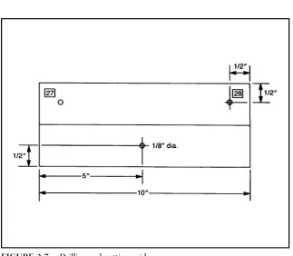
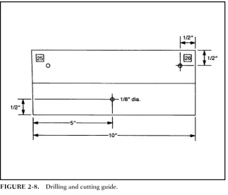
that piece. The figures depict each piece as if it were laid lengthwise with its two edges on a workbench then flattened so both sides could be seen. All the figures show the locations and diameter of the holes to be drilled. The locations of the 45-degree angle cuts to be made at the ends of many of the aluminum pieces are shown as shaded areas where the alu-minum is to be removed.
[image:52.432.54.378.61.337.2]Most of the figures are duplicates of each other. The dif-ference between the figures are numbers and sometimes let-ters that appear on the sides of each aluminum piece. The numbers are used when the framework is assembled to the two main sections that make up Questor’s body. The letters are used when these sections are joined together by two con-necting pieces to form the completed framework. In both cases the symbols ensure that all the predrilled holes are in their correct locations when the framework is completed. To mark the numbers and letters on the outsides of each
20 CHAPTERTWO
BODYFRAMEWORK 21
22 CHAPTERTWO
BODYFRAMEWORK 23
24 CHAPTERTWO
[image:57.432.54.378.316.574.2]FIGURE 2-13. Drilling and cutting guide.
BODYFRAMEWORK 25
FIGURE 2-15. Drilling and cutting guide.
[image:58.432.53.378.328.581.2]26 CHAPTERTWO
[image:59.432.55.380.325.581.2]FIGURE 2-17. Drilling and cutting guide.
BODYFRAMEWORK 27
FIGURE 2-19. Drilling and cutting guide.
[image:60.432.54.377.333.583.2]28 CHAPTERTWO
FIGURE 2-21. Drilling and cutting guide.
[image:61.432.54.380.324.587.2]BODYFRAMEWORK 29
aluminum section, first write the correct number or letter on a piece of masking tape and then apply the tape to its proper location according to the figure of that piece.
After all the pieces have been prepared they must again be separated into two groups—one group of pieces for each of the two sections of Questor’s framework. The first group, when assembled, forms the robot’s upper framework. The pieces needed are as follows: four 36-inch- and six 10-inch-long pieces.
[image:62.432.55.332.61.355.2]The second group forms the lower section of the frame-work and the pieces needed are: ten 20-inch and four 6-inch pieces. Of the ten 20-inch pieces for the lower section of the robot, only eight are needed. The remaining two are used as connecting pieces between the lower and upper framework. These two pieces can be identified by the letters A and B which you should have marked on them.
Now that you have the pieces regrouped, study them and familiarize yourself with these markings. How each section is assembled will become obvious as you study the pieces. The key to the assembly is the markings that allow all the predrilled holes to line up correctly.
ASSEMBLING FRAMEWORK
[image:63.432.54.335.37.348.2]Assembling the framework now becomes a simple matter of matching the ends of the pieces according to the numbers on their ends; and then riveting the matched ends together. Tables 2-2 and 2-3 list the numbered ends used in the matching sequence for each of the two sections of the robot’s framework. Table 2-2 is for the upper section and Table 2-3 is for the lower section.
BODYFRAMEWORK 31
After you have matched the pieces, line up the predrilled 1/8-inch holes at the ends of each piece. If the holes on the pieces do not line up (which happened to me three-quarters of the time), clamp them together and redrill the 1/8-inch-diameter hole in both pieces at the same time. Next insert a 1/8-inch rivet into the hole and using a rivet gun “pop” the rivet to secure the pieces. The rivet gun you use should come with directions.
Once you have completed both the upper and lower sec-tions of the framework, they must be joined together with two 20-inch connection pieces marked A and B. To begin take the lower section and place it so the two Fs (which stand for front) on the front of this section face you. Then place the upper section within the lower, with its Fs facing you. Figure 2-27 shows where the two connecting pieces are placed; the piece marked A is placed at the front and the piece marked B in the rear. The pieces are held in place by four 1-inch
[image:64.432.55.331.61.347.2]32 CHAPTERTWO
FIGURE 2-26. Drilling and cutting guide.
TABLE2-2. Matching List for Upper Framework
CORNERS UPPERFRAMEWORKMATCH ANDRIVETENDSNUMBERED
1 1-9-8-16
2 2-10-3-11
3 4-12-5-13
4 6-14-7-15
5 24-26
6 23-25
7 19-27
8 20-28
[image:65.432.56.332.62.347.2]BODYFRAMEWORK 33
TABLE2-3. Matching List for Lower Framework
CORNERS LOWERFRAMEWORKMATCH ANDRIVETENDSNUMBERED
1 1-17-8-31
2 2-19-3-21
3 4-23-5-25
4 6-27-7-29
5 9-18-16-32
6 10-20-11-22
7 12-24-13-26
8 14-28-15-30
34 CHAPTERTWO
diameter bolt, nut, and lockwasher sets. The upper and lower body are now joined to complete Questor’s framework.
MOUNTING FRAMEWORK ON THE
PLATFORM
The next step in completing Questor’s body is mounting the framework on the mobile platform. If you have chosen to include the vacuum cleaner option in your version of Questor, now is the time when it is installed.
Begin by placing the mobile platform on the floor so that the castor wheel faces you, this is the front of the platform. Next assemble the vacuum cleaner according to the instructions included in the kit. Place the vacuum lengthwise on the plat-form so that the vacuum’s motor faces the rear of the platplat-form and the hose outlet faces front. Make sure that the vacuum’s mounting bracket sits flush with the platform. Once you have the vacuum cleaner positioned correctly on the platform, lower the framework onto the platform so that the Fs on the frame-work face the front of the platform. The vacuum cleaner should fit into the lower section of the framework as it is lowered onto the platform. You will have to move the vacuum about with the lower framework to accomplish this. Figure 2-28 shows how to position the vacuum inside the framework.
BODYFRAMEWORK 35
FIGURE 2-28. Vacuum position in lower framework.
bolt the parts in place. Be sure to place lockwashers on the bolt before the nut is tightened. Figure 2-29 shows how the framework is bolted to the platform.
MOUNTING THE VACUUM OUTLET
The final step for completing the mounting procedure is to attach the vacuum cleaner outlet to the framework; this outlet consists of a hinged door and switch assembly. When the door is opened, the vacuum activates. To use the vacuum you open the door and attach a white vacuum hose to the outlet.
36 CHAPTERTWO
FIGURE 2-29. Bolt attaching framework to platform.
BODYFRAMEWORK 37
then screwed to the bracket and the whole assembly bolted to the lower front section of Questor’s framework utilizing two 1/4-inch predrilled holes at that location. Figure 2-31 shows where and how the outlet assembly is mounted. Now that both the vacuum and outlet are mounted, they must be joined by a short section of black hose included in your vacuum kit. Cut a piece of hose approximately 3 inches long. To connect the vacuum to the outlet, unscrew the outlet from the bracket, then connect the hose to the vacuum. Next connect the outlet to the other end of the hose and screw it back to the bracket. The mounting procedure just described is also used to change the vacuum cleaner’s bags, so it is important that you under-stand this assembly. Questor’s framework is not yet complete.
POWER SUPPLY AND
TEMPORARY
CONTROL BOX
Q
uestor’s systems get their power from a 12-volt battery system. This system is comprised of two 6-volt batteries. You will find as I did that most of the motors, lights, and some electronics for robots require a 12-volt system; the temporary control box is just that. Controls in the box switch the two motorized wheels on Questor’s platform to on/off and reverse thus controlling his direction. There are also two speed con-trols mounted in the box, one for each wheel. The control box is connected to the robot’s platform by a cable of wire; the length is up to you. When wiring these systems make sure you pay close attention to the wiring diagrams.MOUNTING BATTERIES AND
BARRIER STRIPS
Questor gets his power from two 6-volt, gel-type batteries mounted within his lower framework. The batteries are mounted on the right and left sides of the upper framework where it sits within the lower framework. Figure 3-1 shows where one of these batteries is located.
Each of the two batteries is held in place by three 2-inch-long pieces of aluminum angle. (Use the aluminum angle left over from the building of the framework.) Two of these pieces
39
C H A P T E R
T H R E E
40 CHAPTERTHREE
FIGURE 3-1. Location of one of the two 6-volt batteries.
POWERSUPPLY ANDTEMPORARYCONTROLBOX 41
are bolted to the mobile platform, while the third is bolted to the framework itself using a predrilled hole on the framework. Figure 3-2 shows where to drill holes in each of the 2-inch aluminum pieces.
To begin installing the batteries, first take two of the 2-inch pieces of aluminum angle and bolt one to each side of frame-work connecting piece B using two 5/32-inch bolt, nut, and lockwasher sets for each. There are two predrilled holes on each side of the upper framework. Next slide one of the baties under each of the pieces making sure that the battery ter-minals face the front of the platform and that they are sitting in their correct mounting positions. Then place two more alu-minum pieces, with their mounting holes flush with the robot’s platform, snug against the battery. Place one piece against the front of the battery and one against the side; do this to both batteries.
Mark the mounting holes on the platform where each of the four aluminum pieces sit. Remove the pieces and battery and drill the four 5/32-inch-diameter holes in the platform TABLE3-1. Parts List
AMOUNT ITEM
2 6-volt, solid-gel battery, with charger kit
2 DPDT switch
1 SPST switch
1 Project box
1 or more Roll red 18-gauge wire 1 or more Roll black 18-gauge wire
2 2-post barrier strip and mounting screws 1 8-post barrier strip and mounting screws 2 25-watt, 10-ohm potentiometer
6 2-inch piece of leftover aluminum angle
6 1-inch5/32-inch-diameter bolt, nut, and lockwasher set
1 Crimp kit
where marked. Once the holes are drilled, replace the batter-ies with terminals facing the rear, and bolt the four 2-inch alu-minum pieces in place, using four 1-inch 5/32-inch-diame-ter bolt, nut, and lockwasher sets. Figure 3-3 shows the mounting brackets in place. Now you could turn the robot upside down and the batteries will remain in place.
The next step in providing Questor with power is to mount multipost barrier strips at various points on the robot’s plat-form. Figure 3-4 shows what one of these strips looks like. These barrier strips are very important because they allow the
42 CHAPTERTHREE
robot to be wired together with great ease; they also allow you to remove individual components from the robot without disturbing others. Most of Questor’s electrical components use barrier strips.
For now you need only three barrier strips: two 2-post and one 8-post. These two 2-post terminals are permanently mounted on the platform near where the motorized wheel post protrudes through the platform; the exact location is of little importance. The third 8-post strip will be temporarily mounted at the center of the rear edge of the robot’s platform. It will be removed later for use in the remote control system.
WIRING PLATFORM
Now that the power supply and barrier strips are mounted they must be wired together using 18-gauge wire. This wire will be used now and throughout the robot. Figure 3-5 shows a graphic representation of how the platform is wired. When you look at Fig. 3-5, you will notice that all the wires used are either red or black. The red wire represents all the wires that will eventually be connected to the positive pole of the power supply, and the black to the negative pole. While Fig. 3-5 is rather straightfor-ward, a few things must be noted before wiring can begin.
First, the red and blue wires coming from each of the motorized wheels must be connected to their barrier strips. The wires from each wheel are too short and must be extended
POWERSUPPLY ANDTEMPORARYCONTROLBOX 43
using one 6-inch red and one 6-inch black wire for each wheel. Use twist caps or solder the red extender wire to the red wire of the motorized wheel and the black to the blue wire. To connect the extended wire to the barrier strips, twist both wires loosely together and push them up and out of the post of the motorized wheel. This post leads to the inside of the lower framework where the barrier strips are placed. Connect the wire to two of the screw posts on the same side of the strip. Refer to Fig. 3-5 for the exact connections.
Wiring the two 6-volt batteries together is made somewhat difficult because of the small size of the battery post. Instead
44 CHAPTERTHREE
of trying to solder the connecting wire to the battery post, I elected to use what is called a crimp kit. A crimp kit enables you to attach special ends to the wires that allow them to be wired together easily. Figure 3-6 shows the different ends available and the crimping tool.
As illustrated in Fig. 3-7, the batteries are not only wired together but to other components. Two of these are charging plugs that come with the batteries. Also wired between the two batteries is an SPST (single-pole, single-throw) switch. This switch serves two functions: First, it is the main on/off switch for Questor; and two, it separates the batteries when they are being charged (the switch is in the off position at this time). Make sure that you use lengths of wire long enough to allow the charging plugs and switch to reach the rear of the platform where they will be mounted later; for now you can tape the components securely to the platform.
Once you have wired the platform, use the charging plugs and charge the batteries. While the batteries are charging, it takes about 36 hours, you can construct the temporary control box used to control Questor.
TEMPORARY CONTROL BOX
Before you begin to assemble the temporary control box, a brief explanation of how it functions is in order. To begin, the two 6-volt batteries have been wired together to give Questor a 12-volt power source. This power source is then wired to two potentiometers, one for each motorized wheel, within the con-trol box. These potsas they are commonly called, are a type of variable resistor that lowers or raises the voltage coming from the batteries. The pots are used to control the speed of each motorized wheel.
The lowered or raised voltage passes into two double-pole, double-throw (DPDT) switches, again one switch for each motorized wheel. The DPDT switches are actually two switches in one, hence the term double in their description. To reverse the direction of a dc electric motor, you must
46 CHAPTERTHREE
change the polarity of the wires leading to the motor. For example, if the right terminal of the motor is connected to the positive terminal of the power source, and the left to the negative, the motor will run clockwise. Exchange the leads so the right lead is negative and the left positive and the motor will run counterclockwise, or in reverse. The DPDT switch does all this internally so all you do is flip the switch up or down to change the direction of the motor. Also included in these switches is a center on/off position where no power goes to the motor.
After passing through the DPDT switch the voltage reaches one of the two motorized wheels on the robot’s platform, and depending on the position of the switch the motor will run
POWERSUPPLY ANDTEMPORARYCONTROLBOX 47
forward, reverse, or not at all. How this system is used to control Questor will be described later in the chapter.
CONTROL BOX CONSTRUCTION
The temporary control box will house all of Questor’s control electronics in this stage of his construction. The box itself should be approximately 44 inches square to allow room for the various parts. The parts contained in the control box are two heavy duty DPDT switches and two potentiometers like those shown in Fig. 3-8. These components are wired together in the control box then connected to the robot’s batteries and motor-ized wheels via a group of wires taped together in a cable. How the parts are mounted in the control box is up to you; however, Fig. 3-9 shows a recommended layout. To mount the parts you will have to remove the box’s overplate on the control box and drill mounting holes in that plate.
WIRING THE TEMPORARY CONTROL BOX
The wire used in the temporary control box and throughout the robot is an 18-gauge-type colored either black or red. Again, red is for all wires connected to the positive pole of the batteries and black is for all to the negative. This makes it easier to trace
48 CHAPTERTHREE
the various circuits in Questor. The robot’s electronics are not so complicated that you would confuse these wires with others leading to Questor’s various systems.
Figure 3-10 shows how to wire the components in the con-trol box together. The color of each wire has been noted. Try as I might, I was unable to make Questor a completely solder-less project. You will have to solder some of the robot’s compo-nents. Two of these components are the pots in the control box. If you have never soldered before, you could simply twist the wires around the post of the components, but this makes for loose and many times poor electrical contacts. What you can do is twist the wires now and solder them later when you have picked up the skill.
POWERSUPPLY ANDTEMPORARYCONTROLBOX 49
50 CHAPTERTHREE
When you look at Fig. 3-10, you will notice eight num-bered wires coming out of the control box to the barrier strip on the platform. The numbers on each wire correspond with numbers on the posts of the 8-post barrier strips located at the rear of the robot’s platform. Match the numbers on the tem-porary control box to the platform to complete this phase of Questor’s construction.
USING THE CONTROL BOX
The temporary control box is very simple to use. The first thing to do is to activate Questor by flipping the main power switch to the on position. Turn both pots on the control box all the way to the right and then turn the pots slightly to the left. This reduces the speed of both wheels so the robot will travel slow enough for you to get familiar with using the control box. Next flip the two DPDT switches on the control box up and Questor will begin to move slowly forward. If you flip them down he will move backwards. Allow the robot to travel for about 20 feet. You may notice that Questor is veering either left or right. You can correct this using the two pots on the control box. If the robot is veering left, increase the speed of the left wheel slightly, and if he is veering right, increase the speed of the right wheel. This should straighten out Questor while keeping his speed up. You could also straighten the robot’s path by decreasing the speed of the wheel opposite the direction he’s veering. This, however, also slows the robot down and if you are already operating Questor at a slow speed, this could slow him down too much. Later you can use the pots to increase Questor’s speed and then recalibrate his direction.
Turning the robot can be accomplished in one of three ways. The first is to run one motorized wheel forward and the other in reverse; this allows Questor to turn about his center. This method comes in very handy when operating the robot in close quarters. The second way to turn Questor is to turn one wheel off and run the other either forward or reverse, depend-ing on the direction in which you want to go. By steerdepend-ing the
robot in this way, you can make his turns wider and smoother looking. The final method of directing Questor only works with the temporary control box. The pots on the control box are used to vary the speed of the motorized wheels allowing one to overpower the other and veer the robot in the desired direction. This of course is the opposite of what you did to straighten Questor’s path. The remote control system does not have a speed control function built into it, so this method of control cannot be used with this system; but that is not to say you could not design this capability in your robot.
At this point you have completed most of the major work in Questor’s construction. Now is the time to experiment with the robot’s control and refamiliarize yourself with the rest of the book. The next chapter details Questor’s remote control system. If you do not plan to include a remote control system or may plan to include one later, you may skip that chapter. I would, however, recommend you do read it to give you an understand-ing of remote control systems.
REMOTE CONTROL
SYSTEM
W
ireless control has always seemed to fascinate people, and Questor’s remote control system is the heart of his appeal. While the technical aspects of remote control may be a little hard for the novice to grasp, Questor’s remote control system is rather simple in construction. Before I go into detail on how the system is comprised, a brief explanation of remote control is in order.A remote control system consists of three basic components. The first is the transmitter or “encoder.” Moving controls on the transmitter causes it to send or encode signals to the second part of the remote control system, the receiver, or decoder. The receiver gets the signals from the transmitter and then decodes them. Depending on what signal the receiver decoded, it will activate a servo, the third part of the system. Servos are the mechanical part of a remote control system. A wheel or some-times bar on the servo will turn in proportion with the move-ment of the transmitter’s control. This movemove-ment can then be used to directly control the function of a robot, or in Questor’s case to trip switches that control his movements.
Questor’s remote control system is a standard off-the-shelf type like that pictured in Fig. 4-1. Notice the three main parts of the system. The robot requires a system with a minimum of two channels. A two-channel system has two servos; each of the servos is used to control one of the robot’s motorized wheels. The system used in my version of Questor has three channels; the third channel is used to trip two switches that can turn other items on the robot on or off.
53
C H A P T E R
F O U R
54 CHAPTERFOUR
FIGURE 4-1. Three-channel remote control system.
REMOTECONTROLSYSTEM 55 The switches that the servos trip are called leaf switches (Fig. 4-2). A leaf switch is a very small on/off switch that is triggered by depressing a small metal strip or “leaf” on the switch. By using four leaf switches, it is possible to recreate the function of the DPDT switches used in the temporary control box.
A total of eight switches is needed to duplicate the func-tion of the DPDT switches used to control the robot’s motor-ized wheels. One servo is then used to trip four switches in such a way to drive the wheel either forward or reverse. You use the control sticks on the remote control transmitter in the same way as you flipped the DPDT switches on the temporary control box; up is forward, center is off, and down is reverse. If you chose a remote control system with more than two channels, you can use the other servos to trip leaf switches for turning other devices on or off, or control motors (forward, stop, and reverse) within the robot. The third servo of my remote control system is used to turn a horn on and off.
TABLE4-1. Parts List
AMOUNT ITEM
1 2-to-3-channel remote control system 10 Leaf switch and mounting screws
1 10- 10- 1/8-inch plywood square 4 1- 10- 1/8-inch wood strip 4 8-post barrier strip
4 Screw hook 2 Rubber band
1 Small strip of foam rubber
# Spools of 18-gauge black-and-red wire 4 2- 2-inch aluminum corner brace
4 2-inch 1/8-inch-diameter bolt, nut, and lockwasher set 1 4-slot fuse holder
You need only one leaf switch per function if that function is to be turned only on or off. Figure 4-3 shows how the leaf switches are positioned and triggered for either on/off or for-ward/reverse control. By now you’re probably wondering where all this fits inside of Questor. The remote control system (servos and receiver), leaf switches, and other compo-nents are mounted on a motherboard that is then installed inside Questor’s framework.
56 CHAPTERFOUR
MOTHERBOARD
The motherboard is simply a 10- 10- 1/8-inch piece of ply-wood on which all of the components for the remote control system are mounted. The various components consist of the remote control system’s servos, receiver, and battery pack, along with ten leaf switches, four barrier strips, and a four-slot fuse holder. Figure 4-4 shows where each item is placed on the board. The first items to be mounted are the servos.
Cutouts will have to be made in the board to allow the ser-vos to sit flush with the board. To do this, first place the serser-vos evenly spaced on the motherboard and trace around their bases. Cut out the wood where traced and slip the servos in place. The servos’ body should have tabs sticking out along its top edge; these tabs prevent the servo from going all the way through the board and this is where the servos are screwed to the board. Most remote control systems come with either plas-tic wheels and/or star levers that are screwed on the servo’s
REMOTECONTROLSYSTEM 57
motor. Figure 4-5 shows how a star lever looks. For this appli-cation you will need star levers that must be modified by removing four of the star’s legs. What you end up with is a straight bar like that in Fig. 4-6. The bar will trip a bank of leaf switches on either side of the servo.
58 CHAPTERFOUR
FIGURE 4-6. Modified star lever.
In order to be tripped, the leaf switches must line up with the trip bar on the servo. This is accomplished by stacking 10- 1- 1/8-inch strips of wood along each side of the ser-vos, then mounting the leaf switches on the strip. Figure 4-7 shows where to mount the leaf switches on the wooden strip in relation to the servos. Once the leaf switches are mounted, connect the servos to the remote control system’s receiver and by using the transmitter, check to see if the trip bar is activating the switches properly. The order in which the servos are wired to the receiver is not important at this time; however, when the receiver is mounted, the sequence will be detailed so that the control stick on the transmitter activates the proper servo.
Once the servos and leaf switches are operating properly, the barrier strips and fuse box for the remote control system can be mounted to the motherboard. Figure 4-4 shows where to mount these components. With all components mounted, the next step is to wire them together.
REMOTECONTROLSYSTEM 59
WIRING THE MOTHERBOARD
Before you wire the motherboard, cut two notches on each side of the motherboard so the wires will not go past its edge. Figure 4-8 shows how to wire together the components on the motherboard. There are two main rows of barrier strips on the motherboard; the first row is numbered. These numbers cor-respond with numbers on the tabs of the leaf switches; simply wire the matching numbers together. In some cases more than one wire will go to one post on the barrier strip. Use the half of the barrier strip closest to the leaf switches. The color wire used is indicated on the leaf switch: R red, B black. The other row is where the motorized wheel and horn will be con-nected; they too use the matching number system.
The second row is divided into two parts called power grids. The first 8 post (which is one complete barrier strip) is called the positive grid and is where the positive lead of the battery is connected and where all the positive or red wires from Questor’s electronics will be connected. The second 8 post is for the negative or black wires and is called the nega-tive power grid. All the posts on the same side of each grid must be wired together by one wire run from post to post. Be sure not to run a wire between the positive and negative grids; this will cause a short circuit. Figure 4-8 s