June
1983
TABLE OF CONTENTS
256K In Detail -
Part I . . . . . . . . . . . . . . .. 4
Packet Radio . . . 10
Bringing Up the BB II . . . . . . . . . . . 15
dBase II . . . 28
Superfile . . . . . . . . . . . 29
WordStar, Volumes of Hints . . . 31
MicroWyl . . . 33
A Two-Faced Drive for the BB I . . . 34
REGULAR FEATURES
Letters. . . .. 2
C'ing Clearly . . . . . 12
Pascal Procedures . . . 16
On Your Own . . . 19
FORTH words . . . 20
KayPro . . . 24
Technical Tips . . . 38
"THE ORIGINAL BIG BOARD"
OEM - INDUSTRIAL - BUSINESS - SCIENTIFICSINGLE BOARD COMPUTER KIT!
Z-80 CPU! 64K RAM!
(DO NOT CONFUSE WITH ANY OF OUR FLATTERING IMITATORS!)
THE BIG BOARD PROJECT: With thousands sold worldwide and over two years of field experience, the Big Board may just be one of the most reliable single board computers available today. This is the same design that
was licensed by Xerox Corp. as the basis for their 820 computer.
$319
00
(64KKIT
**
BASIC I/O)The Big Board gives you the right mix of most needed computing features all on one board. The Big Board was designed from scratch to run the latest version of CP/M*. Just imagine all the off-the-shelf software that can be run on the Big Board without any modifications needed.
SIZE: 8'12 x 133/. IN. SAME AS AN 8 IN. DRIVE. REQUIRES: +5V @ 3 AMPS + - 12V @.5 AMPS.
FULLY SOCKETED! FEATURES: (Remember, all this on one board!)
64K RAM
Uses Industry standard 4116 RAM·s. All 64K is available 10 Ihe user, our VIDEO and EPROM sections do not make holes In system RAM. Also, very special care was taken In the RAM array PC layout to eliminate potential noise and glitches.
Z-80 CPU
Running at 2.5 MHZ. Handles all 4116 RAM refresh and supports Mode 2 INTERUPTS. Fully buffered and runs 8080 software.
SERIAL 1/0 (OPTIONAL)
Full 2 channels using the Z80 510 andtheSMC 8116 Baud Rate Generator. FULL RS232! For synchronous or asynchronous communication. In synchronous mode, the clocks can be transmitted or received by a modem. Both channels can be set up for either data-communication or data-terminals. Supports mode 21nt. Price for all parts and connectors: $39.95
BASIC 1/0
Consists of separate parallel port (Z80 PIO) for use with an ASCII encoded keyboard for Input. Output would be on the 80 x 24 Video Display.
BLANK PC BOARD - $119
The blank Big Board PC Board comes complete with full documentation (including schematics), the character ROM, the PFM 3.3 MONITOR ROM, and a diskette with the source of our BIOS, BOOT, and PFM 3.3 MONITOR.
24 X 80 CHARACTER VIDEO
With a crisp, flicker-free display that looks extremely sharp even on small monitors. Hardware scroll and full cursor control. Composite video or split video and sync. Character set Is supplied on a 2716 style ROM, making customized fonts easy. Sync pulses can be any desired length or polarity. Video may be inverted or true. 5 x 7 Matrix - Upper & Lower Case.
FLOPPY DISC CONTROLLER
Uses WD1771 controller chip with a TTL Data Separator for enhanced reliability. IBM 3740 compatible. Supports up to four 81nch disc drives. Dlreclly compallble with standard Shugart drives such as the SA800 or SA801. Drives can be configured for remote AC off-on; Runs CP/M" 2.2.
TWO PORT PARALLEL.I/O (OPTIONAL)
Uses Z-80 PIO. Full 16 bits, fully buffered, bl-dlrectional. Uses selectable hand shake polarity. Set of all parts and connectors for parallel I/O: $19.95
REAL TIME CLOCK (OPTIONAL)
Uses Z-80 CTC. Can be configured as a Counter on Real Time Clock. Set of all parts: $9.95
CP/M* 2.2 FOR BIG BOARD
The popular CP/M" D.O.S. to run on Big Board Is available for $139.00.
BIG BOARD SOFTWARE SPECIAL - $149
Through special arrangement with CDL we offer a powerful package of TDL Z-80 software that has a suggested retail of almost $600. Includes: Extended Disk Business Basic, ZEDIT text editor, MACRO II Macro Assembler, LINKER, DEBUG I and DEBUG II. Supplied on 8 in. diskette with extensive manual.
PFM 3.3 2K SYSTEM MONITOR
The real power of the Big Board lies In Its PFM 3.3 on board monitor. PFM commands Include: Dump Memory, Boot CP/M", Copy, Examine, Fill Memory, Test Memory, Go To, Read and Write I/O Ports, Disc Read (Drive, Track, Sector), and Search PFM occupies one of the four 2716 EPROM locations provided. Z-80 Is a Trademark of Zilog.
Digital Research Computers
(OF TEXAS)P.O. BOX 401565 • GARLAND, TEXAS 75040 • (214) 271-3538
TERMS: Shipments will be made approximately 3 to 6 weeks after we receive your order. VISA, MC. cash accepted. We will accept COD's (for the Big Board only) with a $75 deposit. Balance UPS COD. Add $4.00 shipping.
USA AND CANADA ONLY
MICRO CORNUCOPIA
P.O. Box 223
Bend, Oregon 97709
503-382-8048
Editor &
Publisher
DavidJ. Thompson
Graphic Design
Sandra Thompson
Technical Guru
Dana Cotant
Staff Assistant
Dorcas Dsenis
Typography
Pa tti Morris & Martin White
Irish
SetterIllustrator
Gary Whitley
MICRO CORNUCOPIA is the sin-gle board systems journal support-ing systems programmsupport-ing lan-guages and single board systems-including the Big Board, the Big Board II, and the Xerox 820.
MICRO CORNUCOPIA is pub-lished six times a year by Micro Cor-nucopia of Oregon, P.O. Box 223 Bend, Oregon 97709
SUBSCRIPTION RATES: 1 yr.(6 issues)
1 yr.(Canada & Mexico) 1 yr.(other foreign)
$16.00 $20.00 $26.00
All subscription orders payable in U.s. funds on a U.s. bank, please.
ADVERTISING RATES: Available on request.
CHANGE OF ADDRESS: Please send old label and new address.
SOFTWARE, HARDWARE, AND BOOK VENDORS: We would very much like to review your CP/M compatible products for Micro C. Please send material to the Review Editor, Micro Cornucopia.
LETTERS TO THE EDITOR: Please sound off.
CP/M is a trademark of Digital Research, Inc. Copyright 1983 by Micro Cornucopia
All rights reserved
IICBD CDBBIICD.11
June 1983
The Single Board Systems Journal
No. 12
All
Wet!
AlmostSOG.
The Semi Official Get-together (SOG) is almost upon us so we need to get some idea how many of your are planning to
come. If you are even thinking of
com-in·g, be sure to call or write immediately. If you are planning to participate in the Friday afternoon raft trips (profession-ally guided) and/or the cookout which follows, you need to get your $25 per person to us by July 7 so we can reserve a place for you. See the article on the SOG in this issue, and be sure to let us know
right away if you are even considering
coming!
The Slicer
I've been bitten by the 16-bit bug. Whether the byte is fatal or not I'll soon know. I'm getting an 80186 based board called the Slicer from Slicer Computer Inc.
They placed a one-page ad in the May issue of Byte and got about 800 re-sponses (so far) so they are working fe-verishly on the final versions of the monitor and bios so they can start ship-ping boards.
The 80186 is like an 8086 with a few extra math instructions, two DMA chan-nels and 3 timers for starters.
The Slicer contains the 80186, up to 256K RAM, a 1797 double density con-troller (5 and 8 inch drives simultane-ously), SASI interface, a 90 pin expan-sion interface, and two serial ports (up to 38.4 K baud). It does not have a video monitor on board so you you have to use a separate monitor. The board runs at 8
MHz with no wait states. It measures
5.85 by 11.75 inches.
At only $140 for the bare board with documentation, power connector, the monitor in two 2732s, and the source of
monitor and BIOS-it should be just the ticket for those of us wanting to get our feet wet with a real 16-bit machine (rath-er than an 8-bit pretend(rath-er). In fact, it looks like we're going to have a whole new system to fondle and fuss over in ' the pages of Micro C.
Come to the SOG and you'll have a chance to tryout one of the first units in existence and meet Otto Baade, the de-signer.
CO-POWER-88
Guess what else you'll see at the SOG? I purchased Software Publishers
CO-POWER-88 board (I already had SWP's
dual density package) and now have my original BB I running single density Z80, double density Z80, and single/double density CP/M 86.
Anyway, Dana and I hooked up the 8088 board and got it running in just a
few minutes. (It was the easiest MOD
I've ever added to the BB. You boot up in CP /M 80 just like usual and you have the option of using the 8088 memory as a RAM disk (drive M:) or running a Z80 program which suddenly transports you into the domain of the 8088. However:
CP /M 86 Software
I don't have a speck of software to run on under CP/M 86 except the 8086 ver-sions of ASM and ED (groan!) that came with it. I hadn't thought about that when I drooled over the new boards.
You've no doubt seen all those glow-ing ads about new software for CP/M 86, but look at the fine print (the prices) and you'll find that most of the packages are half-again as expensive as their CP/M 80 cousins.
I'm really spoiled by the 100-volume CPMug library I have in the corner and by all the great things you folks send in. For the 8088/86, I'm high and dry.
So, we're going to have to start a new
library. If any of you know a mad 8086
programmer who is writing really great code and tossing crumbs of it here and there for hungry CP/M 86 users to snatch up, then by all means let us know. We'll all practice up on our snatching (I under-stand it looks very much like aerobics).
LETTERS
Dear Editor,
I've found that Smartkey (see issue 5), is a particularly helpful utility program which allows redefinition of the console keyboard. Keys can even be redefined to generate strings.
For example, Wordstar lacks a left
word deletion command. If you don't
like the word you've just typed, you have to delete it one character at a time or else move the cursor to use the "delete word right" command. Smartkey lets you create a macro so that a single key-stroke will delete the word to the left. Smartkey also lets you define cursor and function keys, especially helpful in speeding up multi-key commands. Smartprint, a companion program, real-ly makes it easy to create a translation table for characters going to the printer.
FBN Software has moved. The new address is 16 Coles Place, Torrens ACT 2607, Australia. In the United States, Smartkey continues to be available from Lifeboat Associates, 1651 Third Avenue, New York NY 10028, phone (212) 860-0300, and from ICI Computers, PO Box 255, Aurora OR, 97002, phone (506) 678 2778.
John S. Allen 40 RuggRd Allston, MA 02134
Dear Editor,
We have several Tandon Model 848 Thinline 8" drives here, both single and double sided models. We chose them be-cause they were half height but were also pleased to find them sturdy, well made, and fast.
Then a problem •..
We began to lose data, and I really mean lose data! After very short use (less than a week at a few hours a day) we found tracks on our Dysan disks which had been worn down to the plastic base. We could see right through the clear tracks on the disk!
We tried changing the drive mounting from horizontal to vertical but it didn't help. Then we turned to the service manual which stated:
"The head is loaded into contact with
2
the recording medium whenever the drive lever is latched."
In other words, the heads are loaded against the disk and remain loaded as long as the latch is closed. So the head grinds away the track it's sitting on!
We also find that there is a head load option which consists of a head load sol-enoid, a couple of logic gates and some resistors. There is space on the circuit board for the parts but they aren't in-stalled.
A call to Tandon headquarters re-vealed some interesting news. They are aware of the problem but they will not retrofit any Model 848 with head load option, nor will they sell parts for the modification. The person we talked to insisted that the option must be specified in the original order. (We talked to Renee at 213-993-6644, ext 425.)
She also implied that they will not ser-vice any drive which wasn't purchased from an authorized dealer and I don't know of any mail order outfits which are authorized dealers. So we are out of luck.
In a nutshell, the thinline 848's most of us are buying will, with relatively short use, destroy our disks. You can save yourself some of the grief if you keep the door unlatched as much as possible.
However, anyone planning on pur-chasing Tandons should insist on the head load option, or even better, con-sider buying someone else's drives. Willard E Johnson
Department of Physics California State University Hayward, CA 94542
Editor's 1lote:
Allyone have any inside scoop all Talzdon? Is it really impossible to get this head load optio1l?
You might take a look, Will, at e1lablillg the DC motor timeout so that it will shut itself off immediately after a drive access, or use the BB motor controllille to tum off the drive motor (a1ld thell set the timeout dozVlz to a couple of secollds). However, with their attitude to-ward support, perhaps it's best to stay away from them altogether.
Dear Editor,
Just a quick correction for BB II people. Port 88 is the baud rate generator for se-rial port B. Port 89 is the baud rate gener-ator address for serial port A (opposite what was indicated in issue #11). Jim Skinner
20435 SW Alexander Aloha, OR 97006
Dear Editor,
I have recently joined the ranks of the
BB II owners. The only real problem has
been choosing a monitor. I've been lucky enough to have access to several moni-tors and would like to share my findings. First, if you use the 50Hz patch pro-vided in the documentation (from Taylor Electric), just about any 24/80 monitor will work with the BB II 7X9 controller. The only problem with the 50 Hz vertical rate is that it may beat against you 60 Hz AC. The resulting flicker is most pro-nounced on white and green monitors. With amber phosphor, the flicker is barely evident.
The patch is: ODC,2 ODD,5F ODC,O ODD,6F ODC,7 ODD,18
The Sanyo 18 MHz, 12" green-the USI Pi3 20 MHz, 12" amber-and the Amdek Video 100 12 MHz, 12" B&W, all
work with the BB II. Depending on the
monitor, you might need to change the parameter in the second line of the patch. I have used values between 57h and 5Fh. My choice among the three monitors listed is definitely the USI Pi3.
Also, my 7X9 display appeared to be twinkling because the video was ran-domly dropping dots. This is caused by glitching in the shift register U45. You can fix this by changing U33 from a 74LS30 to a 7430. Another way to fix the problem is to add a 22 pf capacitor be-tween U31 pin 11 and ground.
The last problem is that the BB II com-posite video signal suffers from high fre-quency roll-off. So the horizontal lines appear to be brighter than the vertical lines. This is most apparent when the brightness is turned down low. The fol-lowing mod should fix this.
1. Change U24 from a 74LS86 to a 74S86. 2. Change R13 from 1K to 750 ohms. 3. Add a 22 pf capacitor across R13 (the Sanyo needed 100 p£).
Cole Chevalier 17862 Fitch Irvine, CA 92714
Dear Editor,
I use MicroPro's CalcStar spreadsheet for financial and inventory projections. The problem with CalcStar is that it keeps all data in memory so the size of the spreadsheet is quite limited.
I saw ads for Supersoft's Spreadsheet called Scratchpad. It touted their "VM"
feature. I bought it knowing that it
would be somewhat slower (by defini-tion).
I was really disappointed though with their tedious formula entry. It is so slow that entering a spreadsheet large enough to need virtual memory wouldn't likely
occur during my lifetime. I feel that
scratch pad would be a waste of money at $29.95 and I paid $212.00! I hope other SuperSoft products are easier to use.
Are there any Micro C readers who
would like to work with me on a better spreadsheet?
John Allen
144 Yagi Lane RR #1 Bowling Green MO. 63334
Dear Editor,
I wonder if you or any readers might
shed some light on several problems I have had with my Big Board.
I have noticed that cntl-S will some-times cause an untimely end of the dis-play (while TYPING out a file) rather than just stopping the text.
When I'm in WordS tar with a parallel keyboard, the system can't accept key-board input while it is doing anything else. Any character entered at this time will come out an "F". Occasionally a stray":" will appear in the file, which is bad news if I'm going to be assembling it. I don't have these problems if I'm using a serial keyboard.
If I'm using WordStar to edit a file that is larger than will fit into RAM, I tend to get blocks of errors such as a string of e's or I'll just notice a chunk of text missing or duplicated. Any suggestions? John F Ingham
VK5KG 37 Second Ave Sefton Park
South Australia 5083
Editor's note:
A few shots in the dark. You may have a buffer in the serial keyboard (besides a couple of characters in the 510) and let's see, serial port B generates interrupts but so does the keyboard PIO. During disk access, interrupts are disabled most of the time so you have to send characters quite slowly or the processor will miss them.
It sounds like your parallel keyboard is gen-erating some garbage characters. If your key-board cable is quite long you might get some glitching that would cause thecntl-S problem etc.
As for the large file problem, I'm at a total loss unless you have a marginal drive or a bad copy of WordS tar. What say anyone?
And, by the way, thanks for the nice
com-ments about Micro C.
Micro Cornucopia, Number 12, June 1983
Dear Editor, Dear Editor,
Here is a small correction to Tony Ozrelic's C'ing Clearly on page 12 of is-sue #11. The line "answer = &query;" should read "answer = query;" or "an-swer = &query[O];". Page 89 of The C
Programming Language, Kernighan and
Ritchie state that the & operator can be applied only to variables and array ele-ments. On page 94 they write: "pa
=
&a[O]" can also be written as "pa
=
a". Itried Tony's statement on my Zilog S8000 at work and got a warning.
I have been plagued by video jitter ever since I got my BB up and running. The symptom was that all the dots on a line would move back and forth about 1 dot width.
After verifying that I· had the right crystal, adding extra filtering, checking
the CRT, and everything else I could
think of, I finally located the problem. It was caused by U51 and U38, the series one-shot combination used to generate the horizontal sync pulse.
I realize that this may appear to be picking nits, but after programming and teaching programming for almost ten years, I feel that nit picking perfection-ists make the best programmers. But in the same breath I would like to praise Tony for doing the C column. I think he should be commended for doing a fine job.
I solved the problem by bypassing
U38. Do this by bending out U38 pin 13, and adding a jumper on the bottom of the board from U51 pin 13 to U38 pin 13.
This modification shifted the screen image but my CRT had an adjustable de-lay.
Finally, I think Micro C is the most en-joyable computer magazine I've ever read. Please keep up the good work!
You'll be hearing more from me when I
get off my duff and submit something to either the C or Pascal columns.
The problem is caused either by tion in the width of U51's pulse or varia-tion in the trigger point of U38. If you are having this problem, this fix may work, or you might try a different brand of one-shot.
A simple request: Does anyone know where I can locate the source of the Othello program on user disk #1? I'd really like to try extending it.
Adam S Moskowitz 221 Summer St #2 Somerville, MA 02143
Henry Holcomb 7 Belmont Place Lynchburg, VA 24502
•••
BUYING A BIG BOARD? READ THIS FIRST!
Let us put it together for you. We are experienced at electronics assembly and are set up to produce finished and fully tested Big Boards that you can rely on.
Normal assembly time is less than two weeks. Total charge is $100 or $60 with sockets factory installed plus $5 shipping. Idaho residents add $3 sales tax.
We also repair non-working Big Boards at a price to be determined upon inspection.
Send your kit (or have Digital Research send it) to:
Jay Papillon
PARADISE VALLEY ELECTRONICS 871 N. Eisenhower St.
Moscow, ID 83843
Additional Products
&
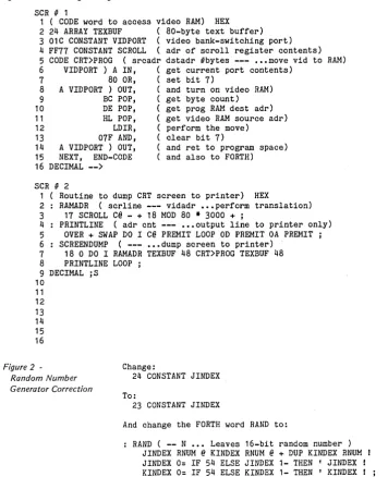
Services : YourEPROM IFORTH (Idaho FORTH) Complete FORTH Monitor
in 4 EPROM's. $35
CRTRAM A debugging aid, Needs no DRAM to run
uses CRT ram for scratchpad. $15
GRAPH2 Graphics Character Generator includes bit mapped graphics characters with normal
&
reverse ASCII character set. Requires a two jumper no trace cut modification.EPROM Burning Service Your program on 8" disk
single density CP/M file to 2708/2716 $15
or 2732/2764. $20
Quantity discounts available
Our EPROM
$55
$20
$20 $25
256K In Detail- Part I
By
Art Boehm
The following article is much larger
than I had planned. However, it covers
not only specific hardware and software modifications but also tools and tech-niques. There should be something here for just about everyone.
Four Banks of RAM
Converting the Big Board to 262K is ac-tually rather straightforward. Most of the work involves rearranging capacitors on the RAM voltage buses.
As Karl- Wilhelm Wacker noted in Mi-cro C, issue 9, U82 (74LS241) has plenty of power to directly drive the RAM Write signal, and that opens a selector bit on U59 (pin 9) that can be used to select be-tween two new bank bits (on pins 10 and 11) to drive A7 of the 64K RAMs.
The obvious choices for new bank bits are System PIO bits A4 (unused) and A5 (bell). If you really can't live without the bell and will never have more than three drives, you could use A2. Or if you never need a remote console, you could just as-sume the keyboard and use A3. But those bits require reworking PFM.
Incidently, we have had this modifica-tion running reliably on both 2.5 MHZ systems and those with the 4 MHZ mod-ification described by Otto Hiller on page 3 of issue 3. The key to reliability is filter-ing, which is why a good deal of the modification involves rearranging the bypass caps.
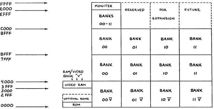
The new bank bits control U13 through U46 (0000 to BFFF). U1 through U8 (COOO to FFFF, i.e. PFM) are not cur-rently switched to avoid the "traveling through hyperspace" problem. You could use compatible 16K parts (i.e. 2118's) for U1 to U8, though we chose all 64K parts (e.g. 4164's or 6664's) to keep our future options open. (See Figure 1)
Since power-up reset selects input mode (and therefore a hi-Z signal) on the System PIO, when PFM moves itself out of the ROM it goes into "bank 3" (A5and A4 are both high) if RAMs U1 through U8 were bank switched. But PFM promptly initializes the PIO port A bits 0 through 2 and 5 through 7 as outputs and these outputs are initially cleared (low) by power up.
So, as execution switches to "bank 1" (bit 5 is low and 4 is high) which of course is notPFM.
4
You can cure this problem by changing PFM INIT3 to put 030h into the port A output register after loading the vector (but before setting the mode). In addi-tion you need to initialize all the bits ex-cept 3 as outputs.
Reworking the board
Before we actually make changes to the board, we must talk about how to re-work a board as complex as the Big Board.
First, remember that it is full of static-sensitive components so be careful. Al-ways ground or discharge (if you've nev-er been discharged before, you ought to try it) yourself before touching the board, and especially before touching any MOS parts (like 65K RAMs).
Second, use the right tools. You would not cut picture frame molding with a chain saw, and you cannot rework a board with such small features without precision (but not necessarily expensive) tools.
Tools You'll Need
1. A 12-18 watt soldering iron with a precision point or micro-spade tip. Any-thing bigger risks foil delamination, burned components, or frequent solder bridges.
2. High quality 21-22 gauge (around 1/ 32") multi-core solder; the thicker stuff just blobs on and makes a mess.
3. Solder removal tools; narrow width (.025-.050) desoldering braid works good but nothing beats a vacuum de-soldering tool. Radio Shack has a mini-de solmini-dering tool (#64-2091) that works great and only costs $6.49. The rubber bulbs don't develop vacuum quick enough to do the job.
4. A wet sponge for keeping the solder tip clean and blob-free, or a combination iron holder and sponge.
5. An X-acto knife with a heavy duty handle (7/16" dia. or more) The thin handle version is not sturdy enough to cut tough foil without risking a snapped blade. Shallow angle blades have to be held too upright to cut easily (and safely).
6. A miniature (i.e. 4") needle or long nose pliers. You cannot get along with-out one, and it should have scored jaws and plastic coated handles.
2000 29th Ave NW New Brighton, Minn 55112 612-633-9292
7. A miniature flush cutting, angle blade pliers. Most other types of cutting pliers can't get in close enough or leave stubs that are too long (and may touch neighboring parts).
8. A needle pointed tweezers; the only reliable way to pickup fragments of 30 gao wire or solder.
9. A set of jeweler'S screwdrivers; you'll need them to adjust your glasses after staring at the board for 15 hours.
10. A way to drill .041" holes; a #59 drill is the correct size, but you need some way to hold it like a pin vise or min-iature drill. You can get these drills with larger shanks for use in a Dremel moto tools.
11. Some 30 gao wire and a 30 gao wire stripper. Finer wire is too hard to work with (much less find or strip) and heavier wire makes too big a lump at the connec-tion points. Besides, if you get some pre-stripped 2.5" lengths, they are exactly the right length for 80% of the jumpers you'll need.
12. A decent ohmmeter. This is in-cluded under rework tools because it is used to verify that yo.ur cuts and adds worked right (i.e. cuts are open and adds are shorts) before you try it out. This is especially necessary when working with the power and ground busing as this change does (+5V should not be shorted to ground when you are done).
Incidentally, cuts will not necessarily show as true opens due to other compo-nents. Mainly you are verifying that there are no shorts.
13. An IC puller and inserter. Big chips you can pry out successfully with a screwdriver. With little chips you get one end or three corners loose and when you grab it to get the rest, it flips over and buries its leads in your finger. Radio Shack has a nice pullerlinserter combo (#276-1574) for $6.95. You can swap all 32 RAMs in 5 minutes with it.
Techniques
Now that you have all these fine new tools, let's talk about technique.
You'll be doing four basic things, re-moving components, adding compo-nents, cutting foils, and adding jumpers.
Removing components
Remove components by first
ing the solder from their leads with a sol-dersucker.
When you have done all the leads you should be able to pull the part out from the component side with a pliers with at most, a touch of the iron to the leads.
Adding components
You have to find a place for new com-ponents to reside. Small comcom-ponents (e.g. diodes, miniature resistors) can go on either the component side or the foil side. Larger components should go on the component side.
Small components can be tacked to a foil on the same side as the component. Scrape the protective coating off the foil and then bend the component lead to jog down and lay on the foil for at least 1/8"
(more if you have room). The solder joint
must provide mechanical strength. Components can also be soldered into vias (the holes that get signals from one board side to the other), or can be in-serted through new .041" holes to inter-cept foils or jumper wires on the other side of the board.
When you cannot solder to a foil on the other side, you must bend the leads
for mechanical strength. If you grab the
lead 1/8" above the hole and push diago-nally down, you should get an L-shaped bend that will work.
By the way, before you drill a hole in the big board, mark your spot and hold the board up to the light to see what is on the other side. You might be surprised.
Cutting Runs
Cutting foils is quite simple. Make two cuts 1/32" to 1116" apart through the foil and "lift" (remove) the piece between the cuts. On boards with quality copper like the Big Board, "lift" really means undercut and scrape. Always check your cuts with an ohmmeter to make sure they worked.
Adding Jumpers
Adding jumpers is similar to adding components, except it is nearly always done on the foil side. You can solder to runs, vias, socket pin, or component pin.
Use 30 guage wire and leave just a little slack (maybe 1116'" extra). On long runs, you can tack the wire to the board in a
Micro Cornucopia, Number 12, June 1983 FFFF
E.OOO
---r---r---,
MO~ITER I I I
RESe.~"ED I FOR. I ~UTURe.. :
I I I
EFFF BA~K5 I I I
I E.XPI'INSION I I
COOO
I I I
00-11 I I I
I I I
BFFF
8A"'K BANK BANK BA~I(.
00 01 10
"
BFFF7FFF
SA"'\( BANK BANK BANK
R.A~VIOEO
BANI(, ·v·' 00 01 1O
"
L{ooo
..
3 FFF
~ ~ ~
I
VIDEO RAI13000 BANK BANK BANK BANK
Z. FFF
r---: OPTION", .. 1\0"'10
0000 I ROM
Figure 1 - Storage Bank Assignment
few places with RTV.
When soldering directly to a pin, watch closely for shorts to nearby pins and foils. To minimize this, melt the sol-der already on the pin/pad, and push or pull the stripped portion of wire down (into the solder) until it touches the pin and the insulation just touches the sol-der. Then clip off the excess wire flush with the solder. If the solder blob is too big, remove it and resolder the pin be-fore again adding the jumper.
BB I Layout
You need to be thoroughly familiar with the layout of the Big Board. It has a component side and a foil side. It also has four quadrants-the CPU, RAM, Video, and I/O. We will use these terms for orientation.
The main ground plane is on the com-ponent side and is generally cross-hatched. There are three main voltage grids in the RAM quadrant: +5, -5, and
+12.
The -5 and + 12 come up the CPU / RAM edge on the foil side, and then run down each of the four RAM rows on the component side. These two supplies al-so have traces at 90 degrees down each of the eight RAM columns (on the foil side). The +5V supply comes from between the video and I/O sections to the CPU side of the RAMs on the component side, and then forms a half-grid by run-ning traces down each of the eight RAM columns on the foil side.
Bypassing
Filtering on the +5V grid is provided by a small capacitor on each end of the column traces (Cl-8 and C78-85).
The filtering on -5V and + 12V supplies is more complicated.
OOV 01 \l lOV /IV
Each supply has a large capacitor on each of the four row traces, (notice that they alternate sides). C21, 38, 51, and 68 filter -5V, while C22, 37, 52, and 67 filter +12V.
The -12V and +5V supplies also have 20 small capacitors (between them) dis-tributed in alternating, interlaced pat-terns down each of the eight RAM col-umns.
In odd numbered columns, the five ca-pacitors (between the +5V filters) (e.g. C13, 25, 39, 55, and 70 in column 1) filter + 12, -5, +12, -5, and +12. In the even numbered columns, the five capacitors between the +5V capacitors (e.g. C14, 26, 40, 56, and 71 in column 2) filter -5,
+ 12, -5, + 12, and -5.
Changes
Now that you have all this straight, the following changes should make perfect sense (See Figures 2,3, and 4).
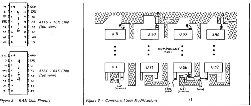
Pin 1 of the present RAMs is tied to the -5V grid. Remove all the filters from the -5V grid (we'll reuse the big capacitors later), cut the -5V supply, and tie the grid HIGH through a pullup and filter. Some 65K rams don't use this pin, but those with internal refresh need to have this pin tied high (to disable the function). (See Figure 2 for pinouts.)
Pin 9 of the present RAMs is tied to the +5V grid. Remove all 16 +5V filters for later reuse. This cuts off the +5V supply. We will also cut all eight column traces between rows 1 and 2. Pin 9 of the RAMs in row 1 will be tied together a~d to ground (COOO-FFFF will always be locat-ed in bank 0). Pin 9 of the RAMs in row 4 (U39-46) will be tied together and to the output of R12, which connects to U59 pin 9.
(continued next page)
[image:7.612.222.566.52.228.2]C.A,'S G
Af> 4776 - 16K Chip A3 (top view) A'I
AS +5
GNO
CAS
Q
M, 4164 - 64K Chip ",3 (top view) All
[image:8.613.47.574.34.256.2]AS A7
Figure 2 - RAM Chip Pinouts
(256K In Detail continued)
Pin 8 of the presen t RAMs is tied to the + 12V grid. Cut off the + 12V supply, tie the grid to +5V, and add all the leftover capacitors for extra filtering.
Disconnect the WRB signal (U82 pin 5)
from U59 and connect it to the RAM
WRB grid directly. Separate U59 pins 11 'and 10 and tie them to system PIO out-puts A4 and A5.
Add extra bypass capacitors to the +5V supply in the video section to as-sure jitter free video, and replace the RAMs.
The actual step-by-step changes are as follows:
1. Remove the -5V filters: C14, 16, 18, 20; C25, 27, 29, 31; C40, 42, 44, 46; C55, 57,59,61; and C71, 73, 75, 77.
2. Remove and save the large -5V fil-ters: C21, 38, 51, 68.
3. Reinstall C21, 38, 51, 68 in roughly their same locations as follows: locating the capacitor bodies on the ground plane, attach the plus leads to the old + 12 (new +5) grid lines emerging from Ul, 20, 26, and 39 (pin 8) by either tack-ing to the lines or ustack-ing vias, and then tack the minus leads to the ground grid.
4. Isolate the +5 filters and new A7 nets by making the following cuts be-tween:
Ui pin 9 and Ci for i=l, 2,3,4,5,6, 7,8(8 cuts)
Ui pin 9 and Ui + 12 pin 9 for i=l, 2, 3,4, 5, 6, 7, 8 (8 cuts)
Ui pin 9 and Ci+39 for i=39, 40, 41, 42, 43,44,45,46 (8 cuts) (e.g. U39 p9 to C78, U40 p9 to C79, etc)
6
•
•
•
•
•
•
•
C.OMPON£t.1T •
51DE
•
•
•
Figure 3 - Component Side Modifications
5. Tie together the new A7 nets by adding the following jumpers:
Ui pin 9 to Ui + 1 pin 9 for i=l, 2, 3,4,5,6, 7 (7 adds)
Ul pin 9 to ground (the uncut foil side of Cl)
Ui pin 9 to Ui + 1 pin 9 for i=39, 40, 41, 42, 43,44,45 (7 adds).
6. On the component side, locate the via by the pin 7 & 8 end of U56. Cut the trace between that via and where it goes under U57 (near pin 7). This isolates WRB from U59 pins 10 and 11.
7. Locate and mark U59 (and pin 9 for reference) on the foil side of the board. Cut the trace between U59 pins 10 and 11, thus isolating those inputs.
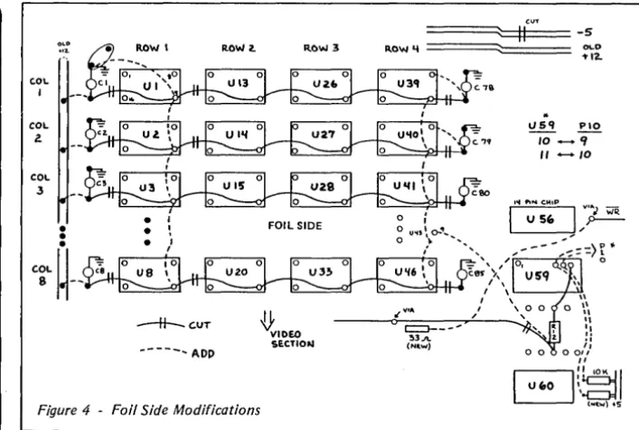
8. On the foil side, cut the trace leav-ing the U60 side of R12. Make the cut where the line jogs (around 1/2" from R12). This isolates the U59 driven WRB signal from the RAM WRB net.
9. Follow the trace you just cut toward the RAMs until you find the first via (around the old location of C68). Solder one end of a 33 ohm resistor in this via, point the free end toward the CPU.
10. Connect one end of a jumper wire to the free end of the 33 ohm resistor, and connect the other end to the via de-scribed in step 6 (find it again on the component side and stick a 30 gao wire through it to locate it on the foil side). Trim the resistor lead with the attached jumper so that it doesn't short to any-thing. This connects the WRB signal to the RAM WRB net.
11. Run a jumper from U43 pin 9 to the U60 side of R12. This ties the new ad-dress selector bit to the RAM A7 grid.
•
\IS
12. Still on the foil side, locate U111, the system PIO. Pin 10 is connected by a component side trace to a via 114" from the pin (toward crystal Y3). Cut the trace from this via on the foil side, it goes to the power connector.
13. Attach the following jumpers on the foil side:
Ul11 pin 9 (Bell) to U59 pin 10 (new A14) U111 pin 10 (Spare) to U59 pin 11 (new A7).
14. Tie 10K pullups to these new U59 inputs. Find a place to put two 10K resis-tors with one end of each tied to + 5 and the other end available on the foil side to be jumpered to U59 pins 10 and 11.
15. On the foil side, cut the -5V power supply trace near C67 next to where the + 12V supply trace jogs. This disconnects -5V from the RAM pin 1 net.
16. Tie the just-isolated RAM pin 1 net HIGH by connecting it to the new +5 grid through a lK resistor and to ground through a .1 uf capacitor. U39 pin 1 has 2 vias within 1/4" for one end of the resis-tor, the other end can be tacked to the new +5 trace coming from U26 pin 8. The trace from U26 pin 1 has a nearby via for one end of the capacitor, the other end should be tacked to the ground plane.
17. On the foil side, cut the main + 12V power bus going to the RAMs up the CPU IRAM edge of the board; make the cut just inboard from TBl (main power connector) pin 4, without disturbing the trace going toward the I/O section.
(continued on page 8)
8
LOW COST DISK CONTROLLER
- LESS THAN $10
COMPLETE-SAVE WEAR AND TEAR ON YOUR DISK DRIVES AND FLOPPIES WITH THE MODEL 3801 ALL SOLID STATE RELAY. SMALL ~NOUGH TO FIT EASILY INSIDE YOUR DISK DRIVE, THE 3801 CAN BE INSTALLED IN MINUTES. YOUR BIG BOARD WILL THEN TURN YOUR DRIVES ON AND OFF AUTOMATICALLY AS THEY ARE NEEDED.
FEATURES
-* SHALL SIZE - 1.75 X 1.40 X 0.35
* FAST INSTALLATION - DIAGRAH INCLUDED
* ZERO CROSSING - ELHlINATES ALL SWITCHING NOISE
* TRIAC OUTPUT - NO HECHANICAL PARTS
* DVDT FILTER - INCLUDED
* LOW COST - ONLY $8.80 EACH
* 1 YEAR WARRANTY
* 30 DAY MONEY BACK GUARANTEE
P ___
JfZ
COMPANY OF CALIFORNIA 1619 SOUTH MINNIE STREET SANTA ANA, CALIFORNIA 9~,"7
(714) 547-4316
CALIF. RES. ADD 6% SALES TAX ADD $1.00 POSTAGE & HANDLING
HARD TO GET PARTS
The Easy WayCOM 8116
CRYSTALS 13.89 MHz 20 MHz 5.0688 MHz
POWER CONNECTOR
RESISTOR PACKS For the Pair
POSTAGE
$12.50
3.00 3.00 3.00
3.00
1.00
2.00
DIGITAL RESEARCH
COMPUTERS
PO ~ox 401565 Garland, TX 75040
(214) 271-3538
C.OL
1
COL
2. OLO
....
ROW 2. ROW 3-H--C.UT
[image:10.617.217.571.31.269.2]-tt'DEO
SECTIONFigure 4 - Foil Side Modifications
(256K In Detail continued)
With a short piece of 20 gao wire, jumper the just-cut end of the main + 12V supply trace to TBI pin 3 (+S volts).
Roughly 3" from TBl, following the power bus toward the RAMs, there is a trace coming off the bus and going to a via by Cl12:
Cut the trace between the bus and the via, and run a jumper from the via to TBI pin 4 (+ 12 volts).
If you had installed the RAM saver cir-cuit, it is no longer needed and should be removed (patch up the + 12V foil).
18. On the foil side, tie the +S power supply to the old + 12V by adding the
following jumpers:
p
'!> \
-J.;q{",(~(~.1 ') Ui pin 8 to Cij;26' cut foil end (+SV side) fori=39, 40, 41, 42, 43, 44, 4S, 46 (8 adds)
19. On the foil side, tie the remaining filters to the +SV supply by tacking short jumpers from the cut foil end lead of Cl, 2,3,4, S, 6, 7,8 to the old + 12 (new +S) bus that runs next to them along the card edge.
20. To assure that the new demand (and noise) on +SV does not affect the video stability, add the following capaci-tors to the ground plane (by tacking or drilling) and vias in the +S lines in the following places:
By U12 pin 14: a 1-10 uf tantalum capaci-tor (+ lead to +SV),
By USI pin 16: a 1-10 uf tantalum capaci-tor (+ lead to +SV),
By U64 pin 18: a SO-100 uf min. electro-lytic (- to ground).
======~::ffl (~UT=== -5
c::>---'-!l3.11.
(N .. ",)
..
0\..0
1'12.
I.ISq !..!.Q. 10 - -'I
" - 1 0
21. Recheck all your work, test for shorts, and make sure the power sup-plies and ground are not shorted togeth-er. Look for solder blobs and splashes or wire fragments. Reflow any cold solder joints and clean up any resin deposits.
22. Pull out the 16K RAMs and care-fully insert the 64K parts.
23. Update your Big Board documen-tation (i.e. prints) to reflect any changes you made.
Your board is now modified and ready to go. Carefully apply power and go for
the magic prompt! If it doesn't work,
re-check your work and proceed as if bring-ing up a new big board. You may have blown out something else while doing the modification. For related articles see Micro Cornucopia-issue 4, page 16, and issue 9, page 8.
The list of parts needed to make the change is as follows:
You need 32 64K RAMS (or 24 64K RAMS and 8 compatible 16K RAMs). The RAMs should be 200ns or better (es-pecially if you intend to go to 4 MHz).
resistors:
1-33 ohm (anti-ring damper)
l-lK ohm (n~t pullup)
2-10K ohm (input pullup) capacitors:
1-.1 uf disc 2-S uf tantalum 1-100 uf electrolytic
Editor's note: This is the hardware portion of this article. Next issue, we'll look at the software ramifications (heh, heh) of these mods. Art also included some really super in-formation on correcting video shake for good. (Issue 13 is already looking pretty lucky.)
•
••
NEW LOWER PRICES!
NOW IN "UNKIT"* FORM
TOO!
"BIG BOARD II"
4 MHz Z80·A SINGLE BOARD COMPUTER WITH "SASI"
HARD·DISK INTERFACE
$795 ASSEMBLED
&
TESTED
$545 "UNKIT"*
$245 PC BOARD WITH 16 PARTS
Jim Ferguson, the designer of the "Big Board" distributed by Digital Research Computers, has produced a stunning new computer that Cal- Tex Computers has been shipping for a year. Called "Big Board II", it has the following features:
• 4 MHz Z80-A CPU and Peripheral Chips
The new Ferguson computer runs at 4 MHz. Its Monitor code is lean, uses Mode 2 interrupts, and makes good use of the ZSO-A DMA chip.
• 64K Dynamic RAM + 4K Static CRT RAM + 24K E{E)PROM or Static RAM
"Big Board II" has three memory banks. The first memory bank has eight 4164 DRAMs that provide 60K of user space and 4K of monitor space. The second memory bank has two 2KxS SRAMs for the memory-mapped CRT display and space for six 2732As, 2KxS static RAMs, or pin-compatible EEPROMS. The third memory bank is for RAM or ROM added to the board via the STD bus. Whether bought as a bare board, an "unkit"·, or assembled and tested, it comes with a 2732 EPROM containing Russell Smith's superb Monitor.
• Multiple-Density Controller for
. SS/DS Floppy Disks
The new Cal-Tex single-board computer has a multiple-density disk controller. It can use 1793 or SS77 controller chips since it generates the side signal with TTL parts. The board has two connectors for disk signals, one with 34 pins for 5.25" drives, the other with 50 pins for S" drives.
• Vastly Improved CRT Display
The new Ferguson SBC uses a 6S45 CRT controller and SMC S002 video attributes controller to produce a display rivaling the display of quality terminals. There are three display modes: Character, block-graphics, and line-graphics. The board emulates an ADM-31 with 24 lines of SO characters formed by a 7x9 dot matrix.
• STD Bus
The new Ferguson computer has an STD Bus port for easy system expansion.
• DMA
The new Ferguson computer has a ZSD-A DMA chip that will allow byte-wise data transfers at 500 KBytes per second and bit-serial transfers via the ZSD-ASIO at SSO Kbits per second with minimal processer overhead. When a hard-disc subsystem is added, the DMA chip makes impressive disk performance possible.
CAL·TEX COMPUTERS, INC.
780 E. TRIMBLE ROAD #504 • SAN JOSE. CA 95131 • (408) 942·1424
SIZE: 8.75" X 15.5"
POWER: +5V @ 3A, +-12V @ O.1A • "SASI" Interface for Winchester Disks
Our "Big Board II" implements the Host portion of the "Shugart Associates Systems Interface." Adding a Winchester disk drive is no harder than attaching a floppy-disk drive. A user simply 1) runsa fifty-conductor ribbon cable from a header on the board to a Xebec controller that costs only $295 and implements the controller portion of the SASI interface, 2) cables the controller to a Sea gate Technology ST-506 hard disk or one compatible with it, and 3) provides power for the controller-card and drive. Since our CBIOS contains code for communicating with hard-disks, that's all a user has to do to add a Winchester to a system!
• Two Synchronous/Asynchronous Serial Ports
With a ZSO-A SIO/O and a ZSO-A CTC as a baud-rate generator, the new Ferguson computer has two full RS232-C ports. It autobauds on both.
• A Parallel Keyboard Port + Four Other Parallel Ports for User I/O
The new Cal-Tex single-board computer has one parallel port for an AS911 keyboard, and four others for user-defined I/O.
• Two Z80-A CTCs = Eight Programmable Counters/Timers
The new Ferguson computer has two ZSO-A CTCs. One is used to clock data into and out of the ZSO-A SIO/O, while the other is for systems and applications use.
• PROM Programming Circuitry
The new Cal-Tex SBC has circuitry for programming 2716s, 2732(A)s, or pin-combatible EEPROMs.
• CP/M 2.2**
CP/M with Russell Smith's CBIOS for the new Cal-Tex computer is available for $150. The CBIOS is available separately for $25.
*
The "unkit" is a fully-socketed. wave-soldered "Big Board II". It requires NO soldering, All an "un kit" purchaser must do is carefully insert theprime ICs we supply in the proper sockets and systematically proceed to
bring up and test the board.
"CP M is a registered trademark of Digital Research
Packet Radio
By
Peter
J.
Eaton
WB9FLW
Radio amateurs in Canada, Sweden, and the U.s. have been experimenting with packet radio, a system of computer-based communications. This new mode can provide high-speed communication that is interference resistant and is effi-cient use of the spectrum.
What is packet radio?
Packet radio is a communication of digitally encoded data (similar to tele-type and ASCII) that includes hand-shaking and error detection. The error checking is done by including a frame check sequence (FCS) with each trans-mission (called a packet of data). The re-ceiver acknowledges an error-free pack-et by sending back an acknowledge (ACK) signal.
If the sending station does not receive
an ACK within a certain period of time, it automatically retransmits the packet.
A packet also contains an address, so a packet station will ignore any packets not addressed to it. Since packets are sent in short bursts, many stations can use the same frequency without conflict. On very busy frequencies you might no-tice some delay in sending data or receiv-ing an acknowledgement, but you never hear the other stations.
Requirements
Each station has to have a terminal, a terminal node controller (TNC), and an amateur radio transceiver.
The terminal can be a simple dumb terminal, a printing terminal, a personal computer, or even a mainframe type sys-tem.
Most terminals generate asynchro-nous characters. These characters have 1 or more "marks" (binary l's) which indi-cate where each character begins (start bits) and ends (stop bits). The characters are sent at a specific baud (bit) rate. There is no set time interval between characters.
TheTNC
The terminal node controller (TNC) is
the heart of the system. It has an
asyn-chronous serial port which connects to the terminal (etc.) and an additional port which connects to the transceiver's mi-crophone line, speaker line, and trans-mit control line.
10
The TNC collects the data coming in from the terminal, until it has enough for
a packet. It then attaches a header which
includes the address of the destination and control information for the network,
and it attaches the error checksum and
flags to mark the beginning and end of the packet.
The TNC then sends the packet out through the transmitter at the packet channel baud rate. Usually it produces AFSK modulation, which means it sends one tone for a mark and another for a space.
The receiving TNC decodes the audio tones (from the speaker line), removing and checking the address information
and the checksum. If the packet is
cor-rectly addressed and corcor-rectly received then it passes the information to the ter-minal (at whatever baud rate is appropri-ate for that terminal).
The modem part of the TNC translates the tones into ones and zeros. Most packet radio modems operate at 1200 baud, and the tones are 1200 Hz and 2200 Hz. This is the same pair of frequencies used by the bell 202 (half-duplex) mo-dem which is available as surplus.
The Transceiver
The transceiver (transmitter and re-ceiver) usually operates on the amateur radio 2 meter (144-148 MHz) band. The main requirement is that the transceiver be able to pass 2200 Hz audio tones ade-quately. Most 2 meter rigs will do this.
Handling the Protocol
The functions of the TNC which would be difficult to duplicate on a per-sonal computer are the protocol decod-ing/encoding and simultaneous opera-tor control.
The protocol sets the contents of the packet header and trailer so that the re-ceiving TNCs know the purpose of the packet. For instance, is the packet being used to check into a net? Or is it part of a communication with another station? Or is it simply acknowledging receipt of an-other packet? Meanwhile, the station operator may want to interrupt the pro-ceedings.
Obviously, a system running under a BASIC interpreter would not keep up, so we've had to write the software in
as-35 Norspur, Route 4 Edwardsville, IL 62025
sembly language. If the TNC were
re-placed by personal computers, we would have to write new software for each different computer.
Since the TNC must be constantly lis-tening to both ports while putting pack-ets together or taking them apart, the hardware of personal computers may not even be capable of handling the task.
Editor's note: Peter is obviously not aware of the incredible feats of engineering taken on
by inspired BB owners. The common ham
(amateur radio operator) with his hand-held appliance (I have one too) won't know what hit him if we turn the BB group loose on the airwaves. (Legally, of course!)
Packet Details
A packet is the basic message unit. It
usually consists of text typed in by the operator and sandwiched between the header and the trailer.
During a typical QSO (conversation on the air) a packet would be put togeth-er and sent out each time the optogeth-erator ended a line by hitting a carriage return. The length of the packet is limited to no more than 128 characters. This limitation helps a single user from hogging the fre-quency as well as making sure that the sending and receiving TNCs don't get swamped.
The data inside the packet need not be ASCII characters. They could be BCD, EBCDIC, or even binary data such as .COM files.
The TNC uses a bit-oriented protocol called HDLC (high level data link
con-trol). This protocol was chosen because it
is supported by a single LSI communica-tions chip, which simplifies both the hardware and the software. Also, in this mode, data is transferred faster since in-dividual characters no longer need start and stop bits in this synchronous mode. See Figure 1. (Editor's note: the 280 SID supports HOLC very nicely, handling the CRC and flag generation. It also checks the first byte of the address for a match. See a 280 SID manual for details of HO LC which is also called SOLC)
The address field contains routing in-formation for the packet. This informa-tion may include the destinainforma-tion stainforma-tion, the originating station, and possibly, some intermediate routing instructions.
Identification of the stations might be by network address number or by amateur call sign.
The control field describes the pur-pose of the packet. It identifies packets which are network ins or check-outs, packet acknowledgements, or re-quests for information from net control.
It may also contain a sequence number
for a multi-packet message which must be received in the correct order.
The data field contains the message. The FCS is just another name for a CRC, a fancy checksum.
What is a packet network?
A local area packet network (LAN) is made up of a net control station (station node) and a number of individual sta-tions (terminal nodes). The net may op-erate through a digital repeater which can be a single-frequency repeater or a standard duplex repeater.
As operators sign on to the net, they are assigned address codes by the net control. An operator wanting to talk to another station logged onto the net can simply address his transmissions to that station.
An operator can choose to listen in on all transmissions or just those addressed to him. Of course, he will only send ac-knowledgements for transmissions di-rected to him.
The operator who is acting as net con-trol operates his station just like anyone else; the special net control functions are taken care of by his TNC.
Connecting LAN s
Some stations will be able to access more than one LAN. These stations could be members of both groups and serve as communications links through which packets can move between nets.
[image:13.624.399.565.53.728.2]Plus there are three other ways being considered for transfer of data between LANs.
Figure 7 - Makeup of the HDLC Packet
FLAG
ADDRESS
CONTROL
Micro Cornucopia, Number 12, June 1983
1. TERRACON would be a high-speed ground-based link using UHF and
microwave relays. It could handle most
packet radio communications in the U.S. and Canada. It will probably be a few years before this system becomes useful. 2. AMICON would be a satellite-based utilizing one of the special services channels on the AMSATphase U-B satel-lite. This system will allow intercon-tinental linking with isolated areas which would not be accessible by TER-RACON.
3. SKIPCON is the projected high fre-quency network. The nature of HF prop-agation requires slower data rates (50 to 600 baud) and error correction as well as error detection protocol. Experiments with this long range mode began in 1981.
How to get started.
There are now two TNC designs. The first TNC was designed by the Van-couver (BC) Amateur Digital Communi-cations Group and they sell a bare board with instructions. They also sell a mo-dem kit. This TNC is based on the 8085
and the 8273 HDLC controller. It
in-cludes 4K bytes of 2114 RAM and four 2708s.
The Tucson Amateur Packet Radio Group is testing a second TNC design. This TNC has the modem, radio face, serial and parallel terminal inter-faces and power supply circuit on a sin-gle board. It is based on a 6809 and can containupt048KofRAMandROM. The 1933 HDLC chip on this board is com-patible with the 8273 chip used on the Vancouver group's board.
Editor's note, I don't have the addresses of the two clubs mentioned but hopefully I'll have that information by the next issue. If you can't wait, contact Peter or get on the air and locate folks from these areas who could tell you.
•••
DATA
FCS
FLAG
Complete
SASI
Kit
for the
BB I
All the hardware you
need, plus, all new
Software to interface
your BB I to a hard disk
controller.
NOW ONLY
$99.95
BB II
Drive
Interface
This is the hardware and
software package you
need to run
51/4"
and 8"
floppies simultaneously.
ONLY
$29.95
Available from:
Andy Bakkers
De Gervelink 12
DeneKamp 7591 DT
The Netherlands
Or, if you come to the SOG
(July 30th and 31st), you'll
get a chance to meet Andy
and tryout both packages.
(You could even take one
home!)
C'ing Clearly
Aztec
CII Compiler Ver. 1.05
Manx have given me prompt and cour-teous service. The compiler works like the book (Kernighan & Ritchie) says and has all the features except those indicat-ed above. Would I buy it again if I had to do it over? I think I would.
Review by Bill LaFay
1214 Westridge Circle Lynchburg Va. 24502I
am new to the world of Cprogram-ming. I used to use BASIC for all my pro-gram needs. BASIC was easy to learn and use. C is quite different from BASIC and not being familiar with structured languages, I decided that the C I would buy must follow "the book" (Kernighan
& Ritchie) religiously. Through the urg-ing of a friend, I bought AZTEC C.
Overview
Aztec C comes in two flavors: Integer and Floating Point. Two for the 8080 and two for the Z80. It also comes with its own assembler, linker and librarian. These, according to the user manual, are
a sub-set of Microsoft's M80/L80. If you
have M80 & L80, you can use them along with your personal external libraries.
The compiler is a one pass compiler so all references must be forward. It has switches which: allow the source text to be added to the assembly language out-put as comments; define the length of expression lines in the source program (default is 120), and define the size of in-ternal work tables. The output of the compiler is an 8080 assembly listing in the case of the 8080 versions and ex-panded 8080 for the Z80 versions (not true Z80 mnemonics).
Strengths
1. Compiles for own assemblerllinker or for Microsoft's M80/L80.
2. Initializers on declarations. 3. Random access file I/O.
4. Very complete error message defini-tions.
5. Compilation, assembly, and linking under SUBMIT file.
6. Suppprts 16 significant digit floating point arithmetic.
7. FP exponent range E+-128. 8. Dynamic storage allocation.
9 .. MAC compiler output can be hand optimized.
10. Structures, pointers, casts.
11. Long, Float, Unsigned, double, static, register, extern.
Weaknesses
1. Calls must have same type & number of arguments as the called function. 2. No FCALL function for calls to exist-ing FORTRAN LIBRARY routines. 3. Internal floating point notation is not
12
compatible with the MICROSOFT FOR-TRAN or BASCOM conventions. 4. No tracer option for single step de-bugging. ZSID must be used on the .COM file.
5. No built-in utility for easy debugging. 6. No code optimization option.
7. No bit fields. 8. No pipes.
Documentation
The manual is new with this version and is chock full of information. It gives good coverage of all facets of Aztec sys-tem operation.
MANX SOFTWARE SYSTEMS sent an update disk that included the needed libraries called for by the linker. This saved a lot of compiling, assembling etc. The user's guide seems to contain the information needed but it is "impossi-ble" for the uninitiated. I've seen much better and would hope the needed im-provement will be made.
Ease of Use
The submit file that comes with the package makes compiling, assembling, and linking very easy. I use the CZII floating point compiler with M80 & L80 and it works very nicely.
Code Size And Quality
The Aztec C is a single pass compiler and does no optimizing but still gener-ates good code. The CLIBZ80 library is large and no doubt accounts for the large object file size.
Conclusions
There were a number of problems with the early versions of the floating point compiler (CZII) but now things seem to be in good shape. The people at
For the benchmark test, I used the same program as shown on page 4 of August 1982 Micro-Cornucopia. I also am running a 4MHz Big Board.
Benchmark Results 4MHZ Z80 Bigboard
Compile Time 16 sec Assembly Time(M80) 16 sec Linker Time(L80) 51 sec Run Time:
-original prog. 32 sec -static variables 22 sec -register int var. 22 sec
Object File Size 17K (.COM)
NOTE: I have written my own version of the trig functions I needed. They are ~ritten in Aztec C and are accurate to 9 Significant digits which is fine for almost all applications. These will work for Az-tec C version 1.04 which doesn't have them.
They should also work on any C com-piler that handles double precision num-bers. I have also interfaced Aztec C with the MICROSOFT FORTRAN library. This speeds up computations by a factor of3.
Editor's note: Any novice who is writing trig functions has my vote for "novice of the year." Also, version 1.05 not only adds such things as I/O redirection, the scientific math junctions, scanf, and relative byte support for unbuffered I/O-it also has a fancy new manual. And still, it is available (to Micro C readers only) at $149.00 Anyone interested in Bill's scientific routines and FORTRAN library interface should contact Micro C. If you are interested we will put them together as a user disk.
Manx Software Systems
PO Box 55
Shrewsbury NJ 07701
201-780-4004 • • •
CP/M 2.2 License and disk for Scull-Tek Big Board ... $95.00
Reconfiguration of above for Ferguson Big Board or Xerox 820 ... 510.00 CP/M manuals ... $20.00
C-DIFF file compare utility for CP/M ... $29.95
With an assortment of public domain utilities to fill the disk.
Wabash 8 inch SSSD diskettes. . . .. 10 for $30.00
plus $2 shipping per box of 10
CP/M Public Domain Software Collections
Add $2.00 each to copy CPMUG. RCPM or SIGM disks onto new disks Specify which disk numbers you want. There are over 200 disks full of public domain software available in these three collections. The best way to find out what is available is to order a box of 10 disks plus $20 for copying and specify that you want the catalogs and abstracts. which will fill all ten. then after you read the abstracts order the disks you have picked out. Quantity discounts and custom CP M configurations available Spnd S 1 for catalog which describes the abovp and other Items In more detail
Illinois residents add 5% sales tax. CP/M is a trademark of Digital Research. Inc
ENCLOSU RE
The home for your BIG BOARD ~hat you will beproud of. With a POWER SUPPLY that will run
the BIG BOARD and two standard or slim-line eight inch drives. It
comes fully wired with all connectors and is pre-wired for disk
expansion. The BIG BOARD mounts on the inside of the top cover
allowing all cables to dress neatly to the rear of the cabnet and to allow ease of access for repair.
The enclosure comes in single or double wide. The double
wide will fit both standard drives or (with the adaptor, $10)
the over sized Shugart SA 800-2, from Cascade Electronics, Inc.
Available without connectors and un-wired as a drive cabinet or as a dO-it-yourself enclosure for the BIG BOARD or other SBC.
STANDARD FEATURES INCLUDE
*
*
*
*
*
*
*
Power supply
+S.OV @ 4A w/OVP, +24V @ 2.SA, ±12V @ 200mA
all voltages have over current prtection.
Fan
Key lock power switch
AC outlets, one switched
Composite video jack
*
*
*
*
Reset switch
Bell circuit and speaker
Solid state AC relay
Reverse video switch
Disk drive exansion pre-wired (SO pin + DC + AC)
Color- hiege and chocolate
*
Optional- adapters & plates*
6"11 x 13"W x 16"0 or 24"W for the double wide.KEYBOARD
The key board was designed to complement the'La Caja' enclosure in color, design and
function and to be 100% compatible with the BIG BOARD.
FEATURES
*
66 keys*
two-key roll over*
ASCII 8, positive lo~ic*
Delayed ne~ative strobe*
Sculptured key caps*
Five user defined keys*
Power requirments- +5.0V (d 150mA, -12V (cl 20mA*
Color. biege and chocolate*
1. ')"-2. 5"H x 13"W x 1l"0PRINTER
The BROTHER HR-15 daisy wheel printer iscompact printer that will handle paper up to
13.5 inches.
A variety of orerations have been added to increase clarity.
preCIsion and to emphasize important points. The HR-l5 Prints
super-script and sub-script characters with the ability to adjust
character spaces proportionally and provides automatic
underlining with either hold or red print. For ease of operalion
both daisy wheel and ribbon are enclosed in casettes making
changing trouble free.
In closing, the BROTHER HR-lS makes an excllent choice for
word processing and general printing.
FEATURES
*
*
*
Graphic printing*
Proportional*
2K byte buffer
Bold printing
13 cps
*
Cassette type daisy wheel*
RS-232C or CENTRONICS parallel*
Bi-directional logic seeking head, 1/120, IS, IS, 10positions per inch.
POWER
*
Bi-directional friction platen, 1/48, 6, 4, 3,positions per inch.
* Options- Tractor feed, Auto cut sheet feed
*
Color- biege*
6"H x 19.5"W x 13"0SUPPLY for the BIG BOARD (+5.0V @ 4A w/OVP, +24V @2.5A,
±12V @ 200mA). All supplys have over current prtection (4"H x 3"W
x 11"0, 6.5 lb)
Transformer for the BIG BOARD ss above (3"H x 3"W x 4"0, 5.5 lb)
ASTROTRONICS also sallS disks, ribbons, dllisy wheels and paper
The box (La Caja)
sin~le wide. wired double wide. wired single wide, un-wired douhle wide. un-wired
adaptor for SA 800-2
5)79 5399
5279 5299 5 10
shippin~ and handl ing 5 11)
KEY BOARD wlo cable
shipping and handling
PRINTER, Brother HR-IS
shipping snd handling
POWER SUPPLY $ 95
TRANSFORMER $ 29
$159
$S9S
$ 10
+$5 S&H
+$3 S&H
~
AstroTronics
Call~~~I~o~e~~~ents
1137 TOPAZ 5T. .CP/M EPROM PROGRAMMER
interfaces to BB1 parallel port
SPECIAL INTRODUCTORY PRICE
features are:
(offer expires Sept. 30, 1983)
- Program, Verify, Load, and check for Erased Intel Eproms 2716, 2732(A), 2764, 27128 T.!. Eproms 2516, 2532, 2564
Xicor EEprom 2816A
- 16 k byte memory buffer allows you to work with up to 8-2716 EPROMS at the same time
- Upload and Download Intel Hex Files with the memory buffer
- Edit the data in the memory buffer
- Define your own addresses for the memory buffer so you never calculate where your data is in the memory buffer - Complete screen error messages
- Software source included - Menu driven
- Interfaces to most Z80 CP/M systems with parallel ports and a TPA= 100H
options (available later) - EPROM Emulator
- Adapters for single chip processors
Requires +5 v. @ 300 rna., +25 V. @ 100 rna., and inter-face cabl