U.S. ARMY MEDICAL DEPARTMENT CENTER AND SCHOOL
FORT SAM HOUSTON, TEXAS 78234-6100
DEVELOPMENT
This subcourse is approved for resident and correspondence course instruction. It reflects the current thought of the Academy of Health Sciences and conforms to printed Department of the Army doctrine as closely as currently possible. Development and progress render such doctrine continuously subject to change.
When used in this publication, words such as "he," "him," "his," and "men" 'are intended to include both the masculine and feminine genders, unless specifically stated otherwise or when obvious in context.
The instructional systems specialist responsible for development of this edition was William H. Shade, DSN 471-8906 or commercial (210)221-8906; Academy of Health Sciences, Multimedia Development Branch, ATTN: MCCS-HLD, 2250 Stanley Road (Room 326), Fort Sam Houston, Texas 78234-6130.
The subject matter experts responsible for writing and content accuracy of this edition were from Preventive Medicine Division, DSN 471-8909 or commercial (210)221-8909; Commander, U.S. Army Medical Department Center and School, ATTN: MCCS-MP, Fort Sam Houston, Texas 78234-6100.
ADMINISTRATION
Students who desire credit hours for this correspondence subcourse must meet eligibility requirements and must enroll through the Nonresident Instruction Branch of the U.S. Army Medical Department Center and School (AMEDDC&S).
Application for enrollment should be made at the Internet website: http://www.atrrs.army.mil. You can access the course catalog in the upper right corner. Enter School Code 555 for medical correspondence courses. Copy down the course number and title. To apply for enrollment, return to the main ATRRS screen and scroll down the right side for ATRRS Channels. Click on SELF DEVELOPMENT to open the application and then follow the on screen instructions.
In general, eligible personnel include enlisted personnel of all components of the U.S. Army who hold an AMEDD MOS or MOS 18D. Officer personnel, members of other branches of the Armed Forces, and civilian employees will be considered eligible based upon their AOC, NEC, AFSC or Job Series which will verify job relevance. Applicants who wish to be considered for a waiver should submit justification to the Nonresident Instruction Branch at e-mail address: accp@amedd.army.mil.
For comments or questions regarding enrollment, student records, or shipments, contact the Nonresident Instruction Branch at DSN 471-5877, commercial (210) 221-5877, toll-free 1-800-344-2380; fax: 210-221-4012 or DSN 471-4012, e-mail accp@amedd.army.mil, or write to:
NONRESIDENT INSTRUCTION BRANCH AMEDDC&S
ATTN: MCCS-HSN
TABLE OF CONTENTS
Lesson Paragraphs Page
INTRODUCTION iv
1 INTRODUCTION TO WASTEWATER TREATMENT
Section I. Wastewater Fundamentals... 1-1--1-6 1-2 II. Wastewater Treatment and Disposal ... 1-7--1-11 1-8 III. Septic Tank Practice ... 1-12--1-17 1-24
Exercises ... 1-45
2 WASTEWATER TREATMENT PLANT OPERATION
Section I. Primary Wastewater Treatment... 2-1--2-6 2-2 II. Secondary Wastewater Treatment ... 2-7--2-9 2-17 III. Tertiary Wastewater Treatment ... 2-10--2-13 2-34 IV. Sludge ... 2-14--2-15 2-37 V. Final Effluent and Stabilization
Ponds ... 2-16--2-18 2-43 VI. Package Wastewater Treatment
Plants ... 2-19--2-22 2-46 VII. Operational Tests and Sampling ... 2-23--2-24 2-48
Exercises ... 2-55
3 FIELD WASTE DISPOSAL METHODS
Section I. Human Waste Disposal... 3-1--3-6 3-2 II. Kitchen and Other Liquid Waste
Disposal... 3-7--3-8 3-16
Exercises ... 3-24
LIST OF FIGURES
Figure Page
1-1 Complete wastewater system... 1-9 1-2 A grease interceptor (or inside grease trap) ... 1-10 1-3 P-trap for sanitary plumbing fixture... 1-12 1-4 Good and bad grades for sewer lines... 1-13 1-5 Good and bad plans for sewer lines ... 1-14 1-6 Manhole... 1-15 1-7 Prevention of cross connection in acid or cinder fill ... 1-16 1-8 Flow diagram showing principles of secondary wastewater
treatment ... 1-23 1-9 Septic tank system ... 1-25 1-10 Absorption field system for level ground... 1-28 1-11 A relief line arrangement for serial distribution ... 1-29 1-12 Absorption trench and lateral... 1-31 1-13 Septic tank capacities for wastewater flows up to
14,500 gallons per day ... 1-35 1-14 Household septic tank ... 1-36 1-15 Septic tank with 2 compartments... 1-37 1-16 Septic tank with dosing tank and automatic siphon ... 1-40 1-17 See page pit ... 1-41 1-18 Underdrained sand filter trench ... 1-43 1-19 Subsurface sand filter... 1-44 2-1 Bar screen, hand-cleaned type... 2-3 2-2 Communitor and bar screen ... 2-5 2-3 Sectional drawing of communitor... 2-5 2-4 Grit chamber... 2-6 2-5 Shapes of weirs ... 2-9 2-6 Parshall flume... 2-10 2-7 Circular primary settling tank with powered sludge
scraping and scum skimming equipment... 2-11 2-8 Rectangular primary settling tanks with powered skimming
LIST OF FIGURES (continued)
Figure Page
2-16 Wastewater flow diagram at plants using high-capacity filters... 2-23 2-17 Aerial view of wastewater treatment plant with intermittent
sand filters ... 2-26 2-18 Flow diagram of an activated-sludge plant ... 2-28 2-19 Aeration tank with diffuser tubes ... 2-29 2-20 Contact aerator... 2-30 2-21 Mechanical aeration tank... 2-31 2-22 Step aeration ... 2-32 2-23 Two-stage aeration... 2-32 2-24 Contact stabilization ... 2-33 2-25 Digesters for two-stage digestion ... 2-33 2-26 Digester with floating cover ... 2-38 2-27 Sludge drying bed with concrete walls... 2-40 2-28 Oxidation ponds ... 2-45 2-29 Package wastewater treatment unit... 2-47 2-30 Sampler for sludge and wastewater effluent... 2-52 2-31 Apparatus for collecting dissolved-oxygen samples ... 2-53 3-1 Cat hole ... 3-5 3-2 Straddle trench latrine with hand-washing device... 3-5 3-3 Deep pit latrine ... 3-6 3-4 Bored-hole latrine ... 3-7 3-5 Mound latrine... 3-9 3-6 Burn-out latrine ... 3-10 3-7 Pail latrine in a building (A) and in the open (B) ... 3-12 3-8 Urine soakage pit with pipe urinals ... 3-14 3-9 Trough urinals ... 3-15 3-10 Urinoil urinal ... 3-16 3-11 Soakage trench with barrel filter grease trap (see fig. 3-13)
LIST OF TABLES
Table Page
1-1 Significant colors in wastewater... 1-5 1-2 Minimum distances between components of wastewater
disposal system ... 1-27 1-3 Absorption area requirements for individual residences ... 1-32 1-4 Allowable rate of wastewater application to a soil
CORRESPONDENCE COURSE OF
THE U.S. ARMY MEDICAL DEPARTMENT CENTER AND SCHOOL
SUBCOURSE MD0161
WASTEWATER TREATMENT
INTRODUCTION
Primitive man was confronted with the problem of waste disposal; however, the problem was rather simple in primeval societies. When wastes became unpleasant because of odors and insects, people would simply move away from them. People were few and land was plentiful.
As civilizations developed, man began to realize the need for sanitary disposal of human wastes. Ancient civilizations of the Old World have left ruins of wastewater disposal systems dating as far back as 4,000 B.C. Both the Greeks and the Romans built comprehensive wastewater systems, parts of which are still in operation today.
With the fall of the Roman Empire, the civilization of European retrogressed into the "Dark Ages." In cities and villages, people disposed of excreta and household wastes by throwing them from the window or doorstep into the courtyard or street. It was during this period of history that Europe was swept by great epidemics of typhoid fever, cholera, dysentery, and other diseases. As the more astute members of society began to associate filth with disease, laws were passed pertaining to waste and refuse disposal. Thus, the environment in urban areas was greatly improved and the incidence of disease was diminished.
In the United States, as long as we remained a country of small towns and farms, waste disposal was not a serious problem. But the country grew rapidly. As wastes began to pollute our inland waters, the quality of our water supplies was endangered. In 1855, our first wastewater systems were built in the cities of Boston and Chicago.
Today, the vast majority of our organized communities have wastewater systems. With continued improvements in technology and stricter enforcement of antipollution
legislation, the quality of our environment can be greatly improved. The Army also strives to protect the environment and soldiers from the spread of diseases by training its soldiers in the proper and safe way to dispose of waste.
This subcourse consists of three lessons and an examination. The lessons are:
Lesson 1. Introduction to Wastewater Treatment.
Lesson 2. Wastewater Treatment Plant Operation.
Lesson 3. Field Waste Disposal Methods.
Credit Awarded:
Upon successful completion of this subcourse, you will be awarded 6 credit hours.
Materials Furnished:
Materials provided include this booklet, an examination answer sheet, and an envelope. Answer sheets are not provided for individual lessons in this subcourse because you are to grade your own lessons. Exercises and solutions for all lessons are contained in this booklet. You must furnish a #2 pencil.
Procedures for Subcourse Completion:
You are encouraged to complete the subcourse lesson by lesson. When you have completed all of the lessons to your satisfaction, fill out the examination answer sheet and mail it to the AMEDDC&S, along with the Student Comment Sheet, in the envelope provided. Be sure that your social security number is on all correspondence sent to the AMEDDC&S. You will be notified by return mail of the examination results. Your grade on the examination will be your rating for the subcourse.
Study Suggestions:
Here are some suggestions that may be helpful to you in completing this subcourse:
--Read and study each lesson carefully.
--Complete the subcourse lesson by lesson. After completing each lesson, work the exercises at the end of the lesson, marking your answers in this booklet.
--As you successfully complete each lesson, go on to the next. When you have completed all of the lessons, complete the examination. Mark your answers in this booklet; then transfer your responses to the examination answer sheet using a #2 pencil and mail it to the AMEDDC&S for grading.
Student Comment Sheet:
LESSON ASSIGNMENT
LESSON 1 Introduction to Wastewater Treatment.
TEXT ASSIGNMENT Paragraphs 1-1 through 1-17.
LESSON OBJECTIVES After completing this lesson, you should be able to:
1-1. Select the statement that best describes the aspects of wastewater treatment plants that are significant to public health.
1-2. Select the statement which best describes the major elements of sanitary wastewater and the percentage of each.
1-3. Select the statement that correctly describes the collection, treatment, and disposal systems for wastewater.
1-4. Select the appropriate type of construction, operation, and maintenance of septic tank systems for user needs.
SUGGESTION After studying the assignment, complete the
LESSON 1
INTRODUCTION TO WASTEWATER TREATMENT
Section I. WASTEWATER FUNDAMENTALS
1-1. GENERAL
Wastewater is used water (liquid) and solids that flow to and through the
wastewater collection system. A wastewater collection system consists of all facilities for the collection, transportation, pumping, treatment, and disposal of wastewater.
a. Domestic wastewater or sanitary domestic wastewater is the "used" water originating from businesses, houses, and installations and similar buildings inhabited by people.
b. Storm drainage consists of rain water, street wash, and flood waters.
c. Combined wastewater is domestic wastewater mixed with storm drainage.
d. Industrial wastewater is the wastewater discharged from an industrial process, such as dyeing or papermaking.
1-2. NEED FOR SAFE DISPOSAL OF WASTEWATER
a. Safe disposal of all human and domestic wastes is necessary to protect the health of the individual (soldier or civilian), family, and community and to prevent waste products in our environment. Wastewater may contain fecal matter, industrial wastes such as oils and emulsions, alkalis and strong acids), organic material, and other
dissolved solids. For satisfactory results, such wastes must be disposed of so that they will NOT:
(1) Contaminate any drinking water supply by such means as biological organisms, radiological and chemical agents, or physical material.
(5) Pollute or contaminate the waters of any bathing beach, shellfish breeding ground, stream used for public or domestic water supply, or recreational area.
(6) Give rise to a nuisance due to odor or unsightly appearance.
b. To reach these objectives, those responsible for wastewater disposal must collect the wastewater and change it from a smelly, infectious, unsightly waste into some kind of harmless, inoffensive substance. This involves passing the wastewater through a wastewater treatment device, works, or plant. Responsibilities and means for wastewater treatment and disposal are discussed in the remainder of this text.
1-3. RESPONSIBILITIES FOR WASTEWATER DISPOSAL AT MILITARY
INSTALLATIONS
a. The Department of the Army. The Department of the Army (DA) is responsible for the health of Army personnel wherever they may be.
b. The Corps of Engineers. The Corps of Engineers (COE) is responsible for the construction, operation, and maintenance of all wastewater treatment facilities on Army installations. Actual construction of the wastewater facilities is usually carried out by civilian consulting and construction engineering firms under the direct supervision of the COE. The operation and maintenance personnel are also civilians, who are trained and experienced technicians and engineers. They work under the direct supervision of the installation engineer officer.
c. The Army Medical Department.
(1) Consult and advise. The Army Medical Department (AMEDD) acts in a consulting and advisory capacity in the design, construction, operation, and
maintenance of wastewater facilities.
(2) Survey, inspect, regulate, and report. The AMEDD must at all times know that wastewater is properly collected, adequately treated, and promptly removed, and finally disposed of in such a manner as to create no nuisance conditions or health hazards either to military or civilian personnel. This requires:
(a) Regular and frequent sanitary surveys and inspections of wastewater systems and wastewater treatment plant operations.
(b) Checking the training, experience, and efficiency of operation, maintenance, and laboratory personnel.
(d) Reporting operation data and test results to provide an accurate record of treatment efficiency.
(3) Investigate. The surgeon of a command (Director of Health Services of an installation) exercises supervisory responsibilities through the supporting preventive medicine unit or the medical department activity (MEDDAC) preventive medicine activity. The unit and activity have assigned sanitary engineers and environmental science officers who are qualified to conduct investigations of wastewater treatment facilities and make recommendations to the operating engineer personnel. The
environmental health specialist assists the professional members by collecting samples for analysis and recording observations made during investigations.
(4) Follow Federal, state, and local health laws. The sanitation problems of civilian communities near military installations are of considerable importance. The post may also be located on land not owned by the Federal Government. Therefore, the surgeon of a command must keep abreast of not only Federal, but also state and local health laws pertaining to stream pollution and waste disposal in areas occupied by the command he serves. By knowing pertinent laws, the surgeon can help prevent creation of nuisances and health hazards and unlawful disposal of wastewater and other wastes.
d. Commander. The commander is responsible for health and welfare of the soldiers under his care. He must ensure that the facilities and surrounding area or field conditions are as safe or sanitary as possible. The commander must ensure that his field sanitation team is trained and trains unit personnel to follow established
procedures in the construction and operation of waste facilities so as to dispose of waste properly.
e. Field Sanitation Team. The field sanitation team (FST) is responsible for the basic sanitation and for the protection and training of unit personnel in waste disposal. The FST supervises the construction and maintenance of garbage pits, soakage pits, field latrines, and field urinals. The team assists the commander in inspections of sanitation and waste disposal.
f. Individual Soldiers. Each soldier is responsible for personal hygiene and for following established sanitation and waste disposal policy and procedures.
1-4. PREVIOUS PURIFICATION PROCESSES
excess of their self-purification capabilities. Purification by dilution requires about 20 to 40 times as much water as wastewater. With ever-increasing metropolitan populations, such vast quantities of our unpolluted water are no longer available. Accordingly, Federal water pollution laws now prohibit the discharging of untreated effluents into navigable or interstate waters.
1-5. CHARACTERISTICS OF WASTEWATER
a. Physical Characteristics. These characteristics are concerned with detection of wastewater by using the physical senses: temperature, odor, color, and feel of solid material. Fresh wastewater is turbid, grayish-white in color, and has a musty odor. Small particles of feces and paper are visible in the waste stream, but these will rapidly settle if the wastewater is quiescent. Fresh wastewater becomes stale in 2 to 6 hours, depending upon temperature, nature of materials present, and the addition of oxygen through turbulent flow. Warm wastewater becomes stale more rapidly than cold wastewater. The addition of oxygen helps extend the time that wastewater will remain fresh. Stale wastewater is dark brown to black and has a pronounced hydrogen sulfide (rotten egg) odor. See Table 1-1 for significant colors of wastewater. Frequently, gas bubbles will evolve from the surface. Carbon dioxide (a product of aerobic decomposition and necessary for the support of algae growth) and sometimes methane (a product of anaerobic decomposition which occurs during wastewater digestion) are found in wastewater.
COLOR PROBLEM INDICATED
Gray None
Green, yellow, Industrial wastes not
or other pretreated (paints, etc.)
Red Blood, other industrial
wastes, or TNT complex
Red or other Surface runoff into influent,
soil color also industrial flows
Dark brown to black Hydrogen sulfide
[image:14.612.94.521.389.639.2]Black Septic conditions or industrial flows
Table 1-1. Significant colors in wastewater.
Wastewater is called strong or weak depending upon the amount of oxygen that is required to oxidize and stabilize it.
(1) Dissolved oxygen. Fresh water normally contains dissolved oxygen (DO) in amounts ranging from about six to about 12 parts per million (ppm) parts of water. Fresh wastewater normally will have a DO content within or just below this range. As wastewater becomes stale, the DO is consumed. Thus, the DO of wastewater is a measure of its freshness. Oxygen in wastewater is necessary to support aerobic bacterial action.
(2) Biochemical oxygen demand. The organic matter in wastewater, primarily of human or food origin, is unstable and readily decomposed and oxidized by biological or chemical agents to form more stable substances. This process requires oxygen. The stronger the wastewater, the greater the amount of oxygen that is
required. The biochemical oxygen demand (BOD) is defined as the quantity of oxygen required for the biochemical oxidation of the decomposable (organic) matter at a given temperature within a given time, usually 5 days at 20°C (68°F). It is normally expressed as the 5-day BOD in milligrams per liter (mg/l) or ppm. Average domestic wastewater varies from approximately 150 to 250 mg/l (ppm) 5-day BOD.
c. Biological Characteristics. Bacteria, viruses, and parasites make up the biological characteristics of wastewater. Wastewater contains vast quantities of
bacteria and other organisms that originate in discharged wastes. The feeding activities of these organisms assist in decomposing wastewater. Aerobic bacteria decompose organic matter in the presence of free oxygen. Anaerobic bacteria decompose organic matter that is shut off from free oxygen, such as in the interior of a mass of feces or a dead body. The products of anaerobic decomposition have an extremely unpleasant odor. Matter in which this condition exists is said to be septic. A large number of the bacteria in wastewater are coliform bacteria -- those found in the digestive tract of normal humans. While most of these bacteria are harmless, pathogens will usually be present in wastewater containing the discharges of many persons. It is these relatively few pathogenic organisms that pose the greatest public health hazard. Wastewater that is not properly treated may eventually find its way into a community water source and spread waterborne diseases.
(1) Filterable residuals. Filterable residues comprise about 60 percent of the total residue. These substances in solution are mainly inorganic compounds such as mineral salts, many of which are not removed by conventional wastewater treatment methods.
(2) Nonfiltrable residues. Nonfiltrable residues account for about 40 percent of the total residue. Typical residues found in domestic wastewater are feces, toilet paper, grease, food scraps, hair, and dirt. Considerable quantities of grit will infiltrate into the wastewater system. Domestic wastewater will also contain refuse which should have been disposed of in some other way but which has, accidentally or purposely, been placed in the wastewater system. Examples include broom straws, rags, towels, bandages, sanitary napkins, sticks, match stems, cigarette and cigar stubs, tobacco cans and pipes, denture plates, condoms, dead animals, and a variety of other domestic and industrial materials. Nonfiltrable residues are further subdivided into floating, settleable, and nonsettleable residues. Settleable residues are those that will settle to the bottom in about one hour under relatively quiet conditions. The strength of nonfiltrable residue is determined by filtering a given quantity of wastewater and drying and weighing the filtrate. Nonfiltrable residues are expressed in milligrams per liter (mg/l, or ppm).
1-6. QUANTITY OF WASTEWATER
The organic strength of sanitary wastewater varies through wide ranges.
Usually, wastewater strength is greatest when the wastewater rate of flow is highest and lowest when the flow rate is lowest. The strongest wastewater is normally produced during the morning hours and the weakest at night. Water infiltration into sewers during rainy weather will dilute the wastewater, thus making it weaker.
a. Per Capita Production. For comparison purposes, wastewater flow is commonly reported as average daily flow per person. The variation may be from as much as 200 gallons per capita per day in some large cities to as low as 25 gallons per capita per day in small communities. Reports from many of the permanent and
semipermanent military camps show a much smaller variation in proportion to
population. An average figure is approximately from 70 to 100 gallons per capita per day, or about 70 percent of the domestic water consumption under routine conditions.
b. Hourly Flow. The volume of a domestic wastewater varies widely during each day. The period of peak flow, usually 200 to 300 percent of the average flow, lasts for a few hours after the period of peak water consumption preceding and following breakfast. Secondary periods of high flow normally occur in the early afternoon and again for a few hours in the evening. Minimum flow occurs after 2400 hours to
Section II. WASTEWATER TREATMENT AND DISPOSAL
1-7. GENERAL
Each wastewater disposal system consists of the following: collecting the
wastewater, transporting it to a central location, treating the wastewater to render it safe and innocuous, and disposing of the resulting effluent. Figure 1-1 illustrates a complete wastewater system. For example, wastewater removed may leave a house or dwelling by way of a sewer system. The sewer system structures convey the wastewater to the treatment plant for processing, chlorinating, and disposing of the now treated
wastewater through a connecting outfall sewer.
1-8. OBJECTIVE OF WASTEWATER TREATMENT
The objective of wastewater treatment is to remove as many of the residues as possible and bring the wastewater supply as nearly as practicable back to the quality of the original water supply. Although potable water is never produced at the treatment plant, the wastewater treatment processes at one town or installation are often the first steps of water treatment for those farther down a stream. In any instance, wastewater treatment plant processing should be carried sufficiently far to ensure that no nuisance condition or health hazard will result by the final disposal of the effluent and that the quality of the water in receiving streams is not seriously impaired. In addition, the effluent must meet applicable Federal, state, and local discharge criteria.
1-9. WASTEWATER COLLECTION SYSTEMS
a. Interceptors and Traps. Receptacles, which are preventive maintenance interceptors and traps, in dwellings and buildings serve as waste disposal collectors for other than ordinary household wastewater. These specially designed interceptors or traps are frequently required for prompt removal of troublesome wastes before they enter the wastewater collection system.
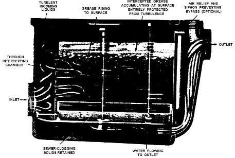
[image:19.612.78.535.295.602.2](1) Grease interceptors and traps. Removing grease from greasy wastes is essential to proper functioning of wastewater systems. Grease is collected in two ways: by ceramic or cast-iron grease interceptors (see Figure. 1-2) installed inside kitchens and other facilities that generate waste grease in comparable or greater quantity, and by concrete or brick grease traps outside the building. Inside grease interceptors are the most common type unit and when properly maintained, they collect about 90 percent of the grease from greasy wastes. Proper maintenance requires daily removal of all solids and washing of all removable baffles, and a complete cleaning weekly.
(2) Hair traps. Hair traps are installed as waste connections or collections in lavatories. These traps are manufactured with baffled partitions and screens to keep hair, lint, and other material out of waste lines. Traps must be cleaned frequently to ensure satisfactory service.
(3) Plaster traps. Plaster traps are installed in waste connections to sinks in hospitals, laboratories, industrial plants, and other places where plaster of paris and other insoluble materials are used. These traps keep foreign material from waste lines. Material accumulating in the traps must be removed frequently to ensure satisfactory service.
(4) Gasoline and oil interceptors. Discharging gasoline, kerosene, or any other volatile liquid into sewers is strictly prohibited. Volatile liquids accumulating in sewers may cause explosions and destroy sewer lines or the treatment plant. They also interfere with proper operation of the plant. Signs of gasoline, lubricating oils, or grease in sewers must be traced to their source. To remove this explosion hazard from the wastewater collection system, gasoline and oil interceptors built on the same
principle as grease interceptors are installed in drains from garages, washracks, and shops where greasy wastes are discharged in manageable amounts. The gasoline, oil, and grease accumulating in the interceptor must be skimmed off at regular intervals to assure effective removal of the hazard.
b. Structures. A wastewater collection system consists of a collection or group of sewer pipes, pumps, and other structures, as necessary, to transport or convey wastewater for treatment and final disposal. These structures include:
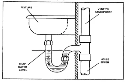
(1) Plumbing fixtures. These fixtures consist of sinks, flush toilets, shower drains, and the like through which waste enters the collecting system. A P-trap (see Figure 1-3) is important in the construction or installation of a plumbing fixture. Weak wastewater remaining in the P-trap acts as a water seal between the fixture and the remainder of the collection system. Accordingly, odors and toxic gases from the sewer do not escape through the fixture but escape instead through the vent in the house sewer.
(2) House sewer. A pipe or pipes connecting the sanitary plumbing
facilities of a single building to a common sewer. A vent pipe which permits wastewater to flow without siphoning the water seal in the P-traps is included as a part of the house sewer.
(3) Lateral sewer. A sewer line connecting to a branch or other sewer and having no other common sewer tributary to it.
Figure 1-3. P-trap for sanitary plumbing fixture.
(5) Main sewer. A sewer line to which two or more branches are connected
(6) Trunk sewer. A sewer with many branches which provides the outlet for a large geographic area.
(7) Force main. A sewer main carrying wastewater under pressure from a pumping station.
(8) Inverted siphon (depressed sewer). A portion of a sewer line that is placed deliberately below the drainage grade of the rest of the line such that the depressed portion is filled with wastewater at all times. It is especially useful for filling pumps at a pumping station.
c. Principles of Design.
[image:22.612.105.512.239.574.2](1) Lateral sewers, branch sewers, and usually, main sewers are laid to permit gravity flow of their contents (see Figure 1-4). Usually the slope is such that the wastewater flow rate is 2 feet per second or more when the line is half full or full. This is known as the "scouring velocity," below which solid material would tend to settle out in the line. Sewer pipes are of sufficient size to carry a peak flow of about 3.7 times the average flow expected from the area served. For gravity flow lines, sewer pipe of vitrified tile; concrete; cement-asbestos; or bituminous-impregnated fiber may be used. For force mains and stream crossings, cast-iron or cement-asbestos pipe is used. Caulking of suitable material is used in the joints.
(2) To the maximum extent practicable, sewers are laid in straight lines (see Figures 1-4, 1-5). Corners and sharp bends slow the flow rate, permit clogging, and make line cleaning difficult. Manholes (see Figure 1-6) are located at each change of slope of a branch or larger sewer and generally are placed at the end of each lateral. Where sewers connect, a Y-channel is formed in the base of the manhole.
Figure 1-5. Good and bad plans for sewer lines.
(3) Care must be exercised in the installation of a wastewater collection system to prevent the occurrence of indirect cross connections.
Figure 1-7. Prevention of cross connection in acid or cinder fill.
d. Pumping.
(1) Requirement. Pumping is necessary if the slope of the wastewater line does not produce required minimum velocity or where wastewater must be lifted to a higher elevation. Wastewater can be pumped through pressure lines (force mains) regardless of their slope, or it can be raised high enough at pumping stations so that gravity provides the required velocity.
(2) Operation. Nonclogging centrifugal wastewater pumps are most
corrodes concrete, masonry, and steelwork. Infrequent or insufficient cleansing of wastewater containers permits the accumulation of gas and explosive vapors. Thus, while the pumping station may be of the automatic type, it still requires daily attention.
1-10. WASTEWATER TREATMENT
There are basically three types of stages or processes that take place to render wastewater for disposal. These processes are called primary, secondary, and tertiary treatment. Likewise, there are three types of treatment plants -- primary, secondary, and tertiary -- that reduce the pollutant load in wastewater and chlorinate it before discharging the effluent into outfall sewer.
a. Primary Treatment. Primary treatment, essentially a physical process, includes the removal of settleable and floating residues. The process order is
screening, followed by grinding or shredding if the facility or equipment is present (in this subcourse, we will assume that it is), and then grit removal, primary clarification of sedimentation, and sludge removal.
(1) Screening and/or grinding. Screening and grinding prevent the entrance into the treatment plant of large objects such as rags, pieces of wood, dead animals, and other objects which may clog pipes, pumps, or other mechanical
equipment. Types of equipment most commonly used are fixed-bar screens and communitors.
(a) Fixed-bar screens -- a series of evenly spaced bars set in the wastewater flow.
(b) Communitors -- machines for cutting or shredding solids and passing them to the wastewater flow.
(2) Grit removal. Grit removal is the preliminary removal of nonfiltrable, inorganic material (sand, gravel, cinders, etc.). This material, if not removed, will
damage pumps and other equipment. It will also settle in digesters (see para 1-10b(4)), thus reducing their capacity and treatment efficiency and necessitating frequent and costly cleaning. Grit removal is accomplished by passing wastewater through a grit chamber that retards the flow enough to permit the grit to settle. There are two types of grit removal units commonly used -- the flow rate controlled grit removal unit and the aerated grit removal unit. These units are discussed in lesson 2.
(a) Septic tank. A septic tank is a device that receives raw
wastewater from a single residence, several residences, a hotel, or an institution. The septic tank retains the wastewater long enough for the settleable residue to accumulate on the bottom. The effluent is discharged through an overflow pipe.
(b) Imhoff tank. An Imhoff tank is a two-story tank that serves a small installation or community. It is a further refinement of the septic tank principle whereby the wastewater enters the upper chamber and, as it passes slowly through, solids settle to the lower chamber. A detention period of 2 to 3 hours in an Imhoff tank will reduce nonfiltrable residue by 45 to 60 percent. Two types of Imhoff tanks are shown in Figures 2-11 and 2-12 of lesson 2.
(c) Separate settling tank. The separate settling tank is the most common device used for primary settling at large installations and municipal wastewater systems. It may be circular or rectangular, having a sloped hopper bottom for the
accumulation of solids. A 2-hour sedimentation period will usually effect removal of 50 to 60 percent of the suspended matter and 30 to 40 percent of the BOD (see para 1-5b(2)). With the addition of chemicals to effect coagulation, as in water treatment, sedimentation may remove as much as 75 to 85 percent of the suspended matter and 50 to 70 percent of the total BOD.
(4) Sludge removal. Removal of sludge is required to ensure continued efficient operation of primary treatment equipment. Sludge from septic tanks is normally pumped into commercially operated tank trucks and disposed of by burial or discharge into municipal wastewater systems. Sludge from the bottom compartments of Imhoff tanks is pumped on a periodic basis, as digestion is completed, into sludge drying beds, tank sludge lagoons, or some similar type of disposal facility. Sludge from primary settling tanks is removed continuously, or frequently, to prevent septic conditions from developing in the tank. It is pumped into sludge digesters for complete digestion (see para 1-10b(4)).
(a) Absorption trenches (subsurface tile fields). These trenches are perforated tile lines laid in gravel beds in loose, porous soil into which the effluent from a septic tank is continuously or intermittently dosed. Oxidation takes place as the effluent percolates through the gravel and soil.
(b) Intermittent sand filters. These are beds of underdrained sand on which settled wastewater is applied. Oxidation takes place in the bed.
(c) Trickling filters. These filters are beds of stone where effluent from primary treatment is intermittently or continuously distributed. Films of organisms that form on the surfaces of the stones stabilize the solids by aerobic methods.
(2) Aeration.
(a) Activated sludge process. This process accelerates aeration whereby the effluent from primary settling is mixed with return sludge and agitated continuously in the presence of oxygen. The activated sludge thus formed has the property of absorbing dissolved organic material and converting it into stable substances that will settle.
(b) Oxidation pond. The pond is a relatively large, shallow pond, either natural or artificial, into which settled wastewater is discharged for natural purification under the influence of sunlight and air.
(3) Secondary settling. Sedimentation is an essential step following biochemical processes such as the trickling filter and the activated sludge process. These biochemical processes do not remove organic material; they convert it to a stable form which will settle out by sedimentation. The sludge from final settling tanks is
pumped into digestion tanks. In the activated sludge process, a portion is returned and mixed with the settled wastewater entering the aeration tanks.
(4) Sludge digestion. The sludge which settles out during primary and secondary sedimentation is about 95 percent water. The remaining 5 percent is highly putrescible organic matter. It is normally pumped directly into covered tanks and
permitted to digest by anaerobic bacterial action. In the Imhoff tank and the septic tank, the sludge settles to the bottom where it is digested anaerobically. Digested sludge is withdrawn and discharged into sludge drying beds. These beds are usually provided with underdrains to facilitate drying. Dried, well-digested sludge is quite stable and is an excellent low-grade fertilizer.
Federal Government has placed increased emphasis on these processes and they will be commonplace, or even mandatory, in the near future. Tertiary wastewater treatment (also referred to as advanced wastewater treatment) may include, but is not limited to, any or all of the following processes.
(1) Carbon absorption. Activated carbon particles are contacted with a flow of wastewater. Dissolved organics are removed from the liquid by adsorption (clinging) to the surface of the carbon particles. Depending on the method, particulate matter may also be removed.
(2) Coagulation-sedimentation. A colloidal suspension consists of particles separated by a dispersing medium. In wastewater, this medium is usually water.
Colloid particles can be removed by coagulation. Coagulation is the process of forming gelatinous particles by reducing the repulsive forces between colloids as a result of adding a coagulant. The resulting coagulated groups can be separated from water by sedimentation.
(3) Chemical oxidation. Oxidation by the use of such chemicals as ozone, hydrogen peroxide, and other chemically unstable substances is used to remove
dissolved organics, phosphates, and nitrogen compounds. By removing unit electrical charges from these other elements, oxidating agents can alter their physical and chemical properties so as to cause their removal from the water.
(4) Membrane processes.
(a) Electrodialysis. Electrodialysis is a means of removing certain elements from a liquid such as water by electromagnetically forcing the elements
through a semipermeable membrane. This method is based on the fact that all charged particles in the solution may be attracted, but only particles of a certain kind may
actually physically cross the membrane.
(b) Reverse osmosis. Two solutions of differing strengths are placed in proximity to one another and separated by a water-permeable membrane. Applying pressure to the chamber containing the stronger solution causes a flow of water from the stronger solution to the weaker solution.
disinfection process is applied. Therefore, chlorination is frequently applied to a treatment plant effluent just prior to its disposal into a receiving stream. Properly
controlled chlorination of a wastewater plant effluent will effect a 99.5 percent reduction in total bacterial content.
(7) Disposal. The final effluent from a wastewater treatment plant is normally discharged into a body of water such as an ocean, lake, or stream. This discharged effluent must not create a nuisance; it must not exert harmful effects on the receiving stream or land; and it must meet Federal, state, and local criteria for effluents (see para 1-8).
1-11. SUMMARY
a. Primary wastewater treatment includes:
(1) Screening.
(2) Grinding (includes shredding).
(3) Grit removal.
(4) Sedimentation.
(5) Sludge removal.
b. Secondary wastewater treatment includes:
(1) Aerobic biochemical processes:
(a) Filtration.
(b) Aeration.
(2) Anaerobic biochemical processes (sludge digestion).
(3) Secondary settling.
c. Tertiary wastewater treatment may include, but is not limited to, one or more of the following:
(1) Carbon absorption.
(2) Coagulation-sedimentation.
(4) Membrane processes.
(a) Electrodialysis.
(b) Reverse osmosis.
(5) Ion exchange.
(6) Chlorination.
(7) Disposal.
Figure 1-8. Flow diagram-showing principles of secondary
Section III. SEPTIC TANK PRACTICE
1-12. GENERAL
a. Reasons for Septic Tanks. Wastewater treatment presents special problems for very small installations or small, isolated units. It is not always economically feasible to install separate wastewater treatment facilities for such installations and units. Whenever possible, a small installation should make arrangements to discharge its wastewater into an adequate public or community system. When no such system is available, where soil and site conditions are favorable, and where it is not prohibited by local and/or state ordinances, a properly constructed and installed septic tank system can be expected to give satisfactory results.
b. Septic Tank Systems. The basic principle of a septic tank system (see Figure 1-9) follows. The liquid contents of the house sewer (A) are discharged into the septic tank (B) where they undergo primary treatment by sedimentation and anaerobic decomposition (secondary treatment) of the sludge that settles out. The treated effluent is discharged into an absorption field (C) where it receives secondary treatment by aerobic bacterial action and is disposed of by percolation through soil. Therefore, before a septic tank system is installed, three important criteria must be met.
(1) It must be determined that the installation of such a system is permitted under all local, state, and Federal ordinances governing the particular locality. This determination may be made by liaison with the local health authorities.
(2) It must be determined that the absorptive capacity of the soil in the locality is sufficient to permit disposal of the effluent without creating a nuisance, such as ponding because of the inability of the soil to absorb the effluent.
(3) It must be determined that the area available for installing the system is sufficient to provide for adequate disposal while maintaining the required distances from underground water sources, buildings, and property lines.
1-13. SUITABILITY OF SOIL
Figure 1-9. Septic tank system.
b. Percolation Tests. In the absence of ground water or subsoil information, subsurface sand explorations are necessary to determination the absorptive capacity of the soil and serve as a basis of design for the liquid absorption. A percolation test of the soil at the actual site of where the disposal field will need to be conducted. The
information gathered will govern the required area needed for the disposal (absorption) field. The recommended procedure, developed by the Robert A. Taft Sanitary
Engineering Center, follows.
(1) Number and location of tests. Six or more tests should be made in separate test holes spaced uniformly over the proposed absorption field site.
(2) Type of test hole. Dig or bore a hole from 4 to 12 inches in diameter, with vertical sides, to the depth of the proposed absorption trench. This depth will depend upon several factors such as differences in elevation between the house sewer and the disposal field, necessary grade for connecting lines, and the depth of the
(3) Preparation of test hole. Carefully scratch the bottom and sides of the hole with a knife blade or sharp-pointed instrument to remove any smeared soil
surfaces and to provide a natural soil interface into which water may percolate.
Remove all loose material from the hole. Add 2 inches of coarse sand or fine gravel to protect the bottom from scouring and sediment.
(4) Saturation and swelling of the soil. It is important to distinguish between saturation and swelling. Saturation means that the spaces or separations between soil particles are full of water. This can be accomplished in a short period of time. Swelling is caused by intrusion of water into the individual soil particle. This is a slow process, especially in clay type soil, and is the reason for requiring a prolonged soaking period. In the conduct of the test, carefully fill the hole with clear water to a minimum depth of 12 inches over the gravel. In most soils, it is necessary to refill the hole by supplying a surplus reservoir of water, possibly by means of an automatic siphon, to keep water in the hole for at least 4 hours and preferably overnight. Determine the percolation rate 24 hours after water is first added to the hole. This procedure is to ensure that the soil is given ample opportunity to swell and to approach the condition it will be in during the wettest season of the year. Thus, the test will give comparable results in the same soil regardless of whether the test is made in a dry or in a wet season. In sandy soils containing little or no clay, the swelling procedure is not essential and the test may be made as described in paragraph 1-13b(5)(c) after the water from one filling of the hole has completely seeped away.
(5) Percolation-rate measurement. With the exception of sandy soils, percolation-rate measurements are made on the day following the procedure described in paragraph (4), above.
(a) If water remains in the test hole after the overnight swelling period, adjust the depth to approximately 6 inches over the gravel. From a fixed reference point, measure the drop in water level over a 30-minute period. This drop is used to calculate the percolation rate.
(b) If no water remains in the hole after the overnight swelling period, add clear water to bring depth of water in the hole to approximately 6 inches over the gravel. From a fixed reference point, measure the drop in water level at approximately 30-minute intervals for 4 hours, refilling 6 inches over the gravel as necessary. The drop that occurs during the final 30-minute period is used to calculate the percolation rate. The drops during prior periods provide information for possible modification of the procedure to suit local circumstances.
1-14. SOIL ABSORPTION SYSTEM
a. Location. When a soil absorption system is determined to be usable, the location of the components must be determined. A safe distance must be maintained between the site and any source of water supply. Since the distance that pollution will travel underground depends upon numerous factors, including the characteristics of the subsoil formations and the quantity of wastewater discharged, no specified distance would be absolutely safe in all localities. Ordinarily, of course, the greater the distance, the greater will be the safety provided. In general, when not in conflict with local
ordinances, the location of components of wastewater disposal systems should be as shown in Table 1-2.
Horizontal Distance (feet)
Component of Well or Water Stream Dwelling Property
System suction supply line
(pressure)
Building sewer 50 10* 50 —— ——
Septic tank 50 10 50 5 10
Disposal field 100 25 50 20 5
*Where the water supply line must cross the sewer line, the bottom of the water service within 10 feet of the point of crossing shall be at least 12 inches above the top of the sewer line. The sewer line shall be of cast iron with leaded or mechanical joints at least 10 feet on either side of the crossing.
Table 1-2. Minimum distances between components of wastewater disposal system.
b. Design. A soil absorption (disposal) field consists of a field of 12-inch lengths of 4-inch agricultural drain tile, 2- to 3-foot lengths of vitrified clay sewer pipe, or
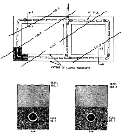
c. Construction. Trenches should be from 1 to 3 feet wide and at least 2 feet deep in order to provide the minimum required gravel depth and earth cover. The spacing between laterals is generally governed by practical considerations dependent on the type of construction equipment, safety, and so forth, but the distance between trenches should be at least twice the depth of gravel. For serial distribution on sloping ground, trenches should be separated by at least 6 feet. Clean, graded gravel or rock ranging in size from 1/2 inch to 2 1/2 inches should surround the pipe. The material should extend from at least 2 inches above the top of the pipe to at least 6 inches below the bottom of the pipe. If tile is used, the upper half of the joint openings should be covered as shown in Figure 1-12. The top of the gravel should be covered with untreated building paper or similar pervious material to prevent the gravel from
becoming clogged by the earth backfill. The top of a new absorption trench should be hand-tamped and should be overfilled with about 4 to 6 inches of earth to prevent the top of the trench from settling below the surface of the adjacent ground. Once a tile field is constructed, fencing or posting to prevent crushing the tile should exclude all heavy vehicle traffic. Planting shrubs or trees over the field is not good practice since the roots tend to clog the tile lines; however, grass over the line assists in removing the moisture and keeping the soil open. Freezing rarely occurs in a carefully constructed system kept in continuous operation.
d. Absorption Area. The required absorption area is dependent upon the results of the soil percolation test and the number of bedrooms served by the system.
(1) Residential requirements. Table 1-3 gives the absorption area
Percolation Required Percolation Required (min per absorption rate (min absorption inch of area in per inch of area in
fall) sq. ft) per fall) sq. ft. per bedroom bedroom
1 70 10 165 2 85 15 190 3 100 30 250 4 115 45* 300 5 125 60* 330
(Provides for garbage grinder and automatic washing machine.) *Unsuitable for seepage pits if over 30.
Table 1-3. Absorption area requirements for individual residences.
EXAMPLE: A 3-bedroom house on a lot where the precolation rate is 1 inch in 15 minutes requires an absorption area of 190 square feet x 3 = 570 square feet. For trenches 2 feet wide with 6 inches of gravel below the
distribution pipe, the required total length of trench would be 570 ÷ 2, or 285 feet. If this were divided into 5 equal portions (that is, 5 laterals), the length of each line would be 285 ÷ 5, or 57 feet. If the laterals are placed 6 feet apart, the width of the field will be 5 (laterals) x 2 (feet wide) = 10 feet, plus 4 (spaces between laterals) x 6 (feet) = 24 feet, or 34 feet. Thus the size of the disposal field must be 34 feet wide x 57 feet long = 1,983 square feet, plus additional land required to maintain minimum distances from wells, property lines, etc.
Percolation Maximum rate Percolation Maximum rate (min per of wastewater rate (min of wastewater inch of application per inch of application fall) per day (gal per sq. ft) fall) per day (gal per sq. ft.) 1 5.0 10 1.6
2 3.5 15 1.3 3 2.9 30 0.9 4 2.5 45* 0.8 5 2.2 60* 0.6
(Garbage grinders and automatic washing machines not included.) *Unsuitable for seepage pits if over 30.
Table 1-4. Allowable rate of wastewater application to a soil absorption system.
EXAMPLE: A small military installation has a daily wastewater flow of 5,000 gallons. The percolation rate is 5 minutes per inch. From table 1-4, the maximum wastewater application rate is 2.2 gallons per square foot per day. Then 5,000 ÷2.2 = 2,270 square feet of absorption area required. If trenches 2 feet wide are used, 2,270 ÷2 or 1,135 linear feet of absorption trenches are required.
If garbage grinders are used, the requirement must be increased by 20 percent:
1,135 + .20(1,135) = 1,362 linear feet.
If automatic washing machines are used, the requirement must be increased by 40 percent:
1.,135 + .40(1,135) = 1,589 linear feet.
If both garbage grinders and automatic washing machines are used, the requirement must be increased by 60 percent:
1,135 + .60(1,135) = 1,816 linear feet.
1-15. SEPTIC TANKS
a. Function. Untreated liquid household wastes will quickly clog all but the most porous gravel formations. A septic tank conditions wastewater so that it may be more readily percolated into the subsoil of the ground. Thus, the most important function of a septic tank is to provide protection for the absorptive ability of the subsoil.
rate of flow is reduced where larger solids can sink to the bottom or rise to the surface. These solids are retained in the tank and the clarified effluent is discharged.
(2) A septic tank combines two processes. Sedimentation takes place in one portion of the tank and the accumulated solids are digested by anaerobic
decomposition in the lower portion. This decomposition or treatment of wastewater under anaerobic conditions is termed "septic," hence the name of the tank. The heavier residues settle to the bottom of the tank forming a blanket of sludge. The lighter solids, including fats and greases, rise to the surface and form a layer of scum. A considerable portion of the sludge and scum are liquefied through decomposition or digestion.
During this process, gas is liberated from sludge. This gas carries portions of the solids to the surface where they accumulate with the scum. Ordinarily, they undergo further digestion in the scum layer and parts settle again to the sludge blanket on the bottom. This action is retarded if there is much grease in the scum layer. The settling is also retarded because of gasification in the sludge blanket. Furthermore, there are relatively wider fluctuations of flow in small tanks than in large units. This effect has been
recognized in Table 1-5, which shows the recommended minimum liquid capacities for household tanks.
Number of Recommended Equivalent
Bedrooms minimum tank capacity
capacity per bedroom
2 or less 750 375
3 900 300
4 1,000 250
Each additional, add 250 ---- 250
(Provides for use of garbage grinders, automatic clothes washers, and other household appliances.)
Table 1-5. Liquid capacity of tanks (gallons).
filtration also remove bacteria. This combination of factors results in the eventual purification of the wastewater effluent.
b. Location. Septic tanks must be located where they cannot cause contamination of any well, spring, or other source of water supply. Underground
contamination may travel in any direction and for considerable distances unless filtered effectively. Underground pollution usually moves in the same general direction as the normal movement of the ground water in the locality. For this reason, septic tanks should be located downhill from wells or springs. Wastewater from disposal systems occasionally contaminates wells having higher surface elevations; therefore, it is also necessary to rely on horizontal as well as vertical distances for protection. Tanks
should never be closer than 50 feet to any source of water supply; greater distances are preferred where possible. The septic tank should not be located within 5 feet of any building. It should not be located in swampy areas or in areas subjected to flooding. In general, the tank should be located where the largest possible area will be available for the disposal field. Consideration should also be given to the location from the
standpoint of cleaning and maintenance.
c. Capacity. Capacity is one of the most important considerations in septic tank design. Liberal tank capacity is not only important from a functional standpoint, but is also good economy. The required tank capacity is based upon the number of bedrooms for individual residences (see Table 1-5) and upon the daily wastewater flow for
institutions (see Figure 1-13).
Figure 1-13. Septic tank capacities for wastewater flows up to 14,500 gallons per day.
tank with the first compartment equal to 1/2 to 2/3 of the total volume provides better nonfiltrable residue removal. The compartments may be individual tanks placed in series or sections enclosed in one continuous shell with watertight partitions separating the compartments (see Figure 1-15). Although capacity is the major consideration in selection of a tank, the following points are also important.
(1) Tank proportions. For tanks of a given capacity, shallow tanks function as well as deep. However, it is recommended that the liquid depth range between 30 and 60 inches and that the minimum plan dimension be at least 2 feet.
(2) Storage above liquid level. Capacity is required above the liquid level to provide for that portion of the scum that floats above the liquid. To allow for this scum storage, the distance from the liquid level to the top of the tank should be approximately 20 percent of the liquid depth (21 percent of the diameter for horizontal cylindrical tanks).
(3) Inlet. The inlet invert should enter the tank at least 3 inches above the liquid level to allow for momentary rises in level during discharges into the tank. A vented inlet tee or baffle should be provided to divert the incoming wastewater
downward. It should penetrate at least 6 inches below the liquid level, but in no case should the penetration be greater than that allowed for the outlet device.
(4) Outlet. The outlet device (or baffle) should extend to a distance below the liquid level equal to 40 percent of the liquid depth (35 percent for horizontal
cylindrical tanks) to provide a balance between scum and sludge storage.
e. Cleaning.
(1) Septic tanks should be cleaned before too much sludge or scum is allowed to accumulate. If either the sludge or the scum approaches too closely to the bottom of the outlet device, particles will be scoured into the disposal field and will clog the system. Eventually, when this happens, liquid may break through to the ground surface and wastewater may back up in the plumbing fixtures. When a disposal field is clogged in this manner, it is not only necessary to clean the tank, but it also may be necessary to construct a new disposal field. The tank capacities, as given before, will ensure a reasonable period of good operation before cleaning becomes necessary. There are wide differences in the rate that sludge and scum will accumulate from one tank to the next. Tanks should be inspected at least once a year and cleaned when necessary. The only way to determine definitely when a tank needs to be cleaned is to measure the depth of the scum and sludge. The tank should be cleaned if:
(a) The bottom of the scum mat is within approximately 3 inches of the bottom of the outlet device, or
(b) Sludge comes within the limits specified in Table 1-6.
Liquid capacity of tank, Liquid depth in feet
gallons 2 1/2 3 4 5
---750 5* 6* 10* 13*
900 4* 4* 7* 10*
1,000 4* 4* 6* 8*
* Distance from bottom of outlet device to top of sludge, in inches.
Table 1-6. Allowable sludge accumulation.
(3) A long stick wrapped with rough, white toweling and lowered to the bottom of the tank will show the depth of the sludge and the liquid depth of the tank. The stick should be lowered behind the outlet device to avoid scum particles. After several minutes, remove the stick carefully. The sludge line can be distinguished by sludge particles clinging to the toweling.
(4) Cleaning is usually accomplished by pumping the contents of the tank into a tank truck. Septic tanks should be washed or disinfected after pumping. A small residual of sludge should be left in the tank for seeding purposes. The material
removed may be buried in an approved sanitary wastewater system. Spillage and leakage during pumping and transporting should be avoided. When a large septic tank is being cleaned, care should be taken not to enter the tank until it has been thoroughly ventilated and gases have been removed to prevent explosion hazards or asphyxiation of the workers. Anyone entering the tank should have one end of a rope tied around his waist with the other end held above ground by another person. An
atmosphere-supplying or self-contained breathing apparatus should be used.
1-16. DOSING TANKS
When the quantity of wastewater exceeds the amount that can be disposed of in about 500 linear feet of tile, a dosing tank should be used in conjunction with the septic tank in order to obtain proper distribution of wastewater throughout the disposal area and give the absorption bed a chance to rest or dry between dosings. The dosing tank should be equipped with an automatic siphon that discharges the tank once every 3 or 4 hours. The tank should have a capacity equal to about 60 to 75 percent of the interior capacity of the tile to be dosed at one time. Where the total length of tile lateral
Figure 1-16. Septic tank with dosing tank and automatic siphon.
1-17. ALTERNATE DISPOSAL METHODS
a. Seepage Beds and Seepage Pits. When the available land area is
insufficient to accommodate a complete soil absorption system, but the soil percolation test indicates an acceptable percolation rate, the following alternatives may be
considered.
never be used where there is a likelihood of contaminating underground waters or where adequate absorption trenches or seepage beds can be provided. In many
localities, seeping beds are prohibited. They are seldom permitted in new construction, being authorized only as an expedient measure where a soil absorption system has failed and space is not adequate for a new one.
b. Sand Filter Trenches and Subsurface Sand Filters. In soil that is relatively impermeable, neither absorption trenches, seepage beds, nor seepage pits are
satisfactory. When absorption systems are impracticable, the possibility of treating the tank effluent in subsurface sand filters or filter trenches may be considered. (Soil testing is a mandatory prerequisite for any subsurface disposal of waste.) These systems are similar to soil absorption systems except that they are deeper, generally somewhat wider, contain an intermediate layer of sand as filtering material, and are provided with underdrains for carrying off the filtered effluent. For this reason, effluent from a properly designed system can sometimes be disposed of without further
treatment. In some jurisdictions, chlorination of the effluent is required.
(1) Sand filter trenches. Sand filter trenches (see Figure 1-18) are
essentially wide absorption trenches (30 to 60 inches wide) underdrained with at least 24 inches of filter and below which open-joint tile lines laid in gravel collect and carry away the filtered effluent.
EXERCISES, LESSON 1
INSTRUCTIONS: Answer the following exercises by marking the lettered response that best answers the question or best completes the statement or by writing the answer in the space provided.
After you have completed all these exercises, turn to "Solutions to Exercises" at the end of the lesson and check your answers. For each exercise answered incorrectly, reread the material referenced with the solution.
1. Which of the following is a responsibility of the preventive medicine specialist?
a. The health of the command.
b. The operation of wastewater treatment facilities.
c. The collection of wastewater samples for analysis.
d. The conduct of investigations of wastewater treatment facilities.
2. Which component of wastewater creates a public health hazard?
a. Grease.
b. Bacteria.
c. Sand and grit.
d. Inorganic solids.
3. Normal sanitary wastewater is approximately ___________ percent water.
4. The organic and mineral matter in wastewater is comprised of about _______ percent filtrable residue and about _________ percent of nonfiltrable residue.
6. At which time can the wastewater flow be expected to be greatest?
a. 0200 hours.
b. 0700 hours.
c. 1500 hours.
d. 2100 hours.
7. Federal guidelines state that the effluent from a wastewater treatment plant, which is discharged into a receiving stream, should meet _____________, __________, and ________________ discharge criteria.
8. What are the essential functions of a complete wastewater system?
a. __________________________________________________________.
b. __________________________________________________________.
c. __________________________________________________________.
d. __________________________________________________________.
9. Average raw wastewater has a 5-day BOD content of approximately:
a. 25-50 mg/l (ppm).
b. 50-100 mg/l (ppm).
c. 150-250 mg/l (ppm).
10. Which of the following are primary wastewater treatment processes? (More than one response may be correct.)
a. Aeration.
b. Filtration.
c. Chlorination.
d. Sedimentation.
e. Sludge removal.
f. Sludge digestion.
g. Screening and grinding.
11. What wastewater treatment process removes contaminants that were not removed by primary and secondary processes? ______________________
12. Properly controlled chlorination of a wastewater treatment plant effluent will reduce the bacterial content by about __________________ percent.
13. Which wastewater treatment processes occur within the septic tank? (More than one response may be correct.)
a. Primary.
b. Secondary.
14. When can a septic tank system be used effectively? (More than one response may be correct.)
a. Adequate space is available.
b. The soil has adequate absorptive properties.
c. The ground water table is at least 50 feet below the surface.
15. In conducting a percolation test, you should determine the percolation rate _____ hours after water is first added to the hole
a. 4.
b. 8.
c. 12.
d. 24.
16. If a percolation test hole has water standing in it after the overnight swelling period, the percolation rate is determined from the drop in water level that occurs during:
a. The first hour.
b. The first 30 minutes.
c. The final 30 minutes of a 4-hour time span.
17. How far should a wastewater absorption field be located from a well?
a. 5 feet.
b. 25 feet.
c. 50 feet.
d. 100 feet.
18. How many square feet of absorption area are required for a septic tank system serving a small unit having a wastewater flow of 10,000 gallons per day, using soil with a percolation rate of 4 minutes per inch of fall? The unit is equipped with garbage grinders in the dining facility.
____________________ square feet
19. How many linear feet of absorption trench does the unit described in exercise 18 need if the trenches used are 3 feet wide?
____________________ feet
20. A septic tank should be located no closer than _________________ feet to any source of water supply.
21. If the per capita flow of wastewater is 100 gallons per day, what is the minimum recommended capacity of a septic tank serving 50 persons?
22. Does the septic tank illustrated below need cleaning? ___________________
23. A septic tank system is to be installed to serve a small unit with an average wastewater flow of 1500 gallons per day. A 2,500 gallon septic tank will be
installed. The soil percolation rate is 30 minutes per inch. Absorption trenches will be 36 inches wide. Will this septic tank require a dosing tank? _____________
If so, how many siphons will be required? _______________________
24. A small unit requiring a septic tank system finds that the soil percolation rate exceeds 60 minutes per inch. Which options may be used?
a. Seepage beds.
b. Seepage pits.
c. Absorption trenches.
d. Sand filter trenches.
e. Subsurface sand filters.